
A8N5X User's Manual for English Edition
Page 1
A8N5X Motherboard
A8N5X Motherboard

A8N5X User's Manual for English Edition
Page 3
... ix Where to find more information ix Conventions used in this guide x Typography x A8N5X specifications summary xi Chapter 1: Product introduction 1.1 Welcome 1-2 1.2 Package contents 1-2 1.3 Special features 1-3 1.3.1 Product highlights 1-3 1.3.2 ASUS Proactive features 1-5 1.3.3 Innovative ASUS features 1-6 1.4 Before you proceed 1-7 1.5 Motherboard overview 1-8 1.5.1 Placement direction 1-8 1.5.2 Screw holes 1-8 1.5.3 Motherboard layout 1-9 1.6 Central Processing Unit (CPU 1-10 1.6.1 Overview 1-10 1.6.2 Installling the CPU 1-10...
... ix Where to find more information ix Conventions used in this guide x Typography x A8N5X specifications summary xi Chapter 1: Product introduction 1.1 Welcome 1-2 1.2 Package contents 1-2 1.3 Special features 1-3 1.3.1 Product highlights 1-3 1.3.2 ASUS Proactive features 1-5 1.3.3 Innovative ASUS features 1-6 1.4 Before you proceed 1-7 1.5 Motherboard overview 1-8 1.5.1 Placement direction 1-8 1.5.2 Screw holes 1-8 1.5.3 Motherboard layout 1-9 1.6 Central Processing Unit (CPU 1-10 1.6.1 Overview 1-10 1.6.2 Installling the CPU 1-10...

A8N5X User's Manual for English Edition
Page 8
.... If possible, disconnect all power cables from the existing system before you add a device. • Before connecting or removing signal cables from the motherboard, ensure that came with the product, contact a qualified service technician or your retailer. Operation safety • Before installing the... motherboard and adding devices on it, carefully read all the manuals that all cables are correctly connected and the power cables are using, contact ...
.... If possible, disconnect all power cables from the existing system before you add a device. • Before connecting or removing signal cables from the motherboard, ensure that came with the product, contact a qualified service technician or your retailer. Operation safety • Before installing the... motherboard and adding devices on it, carefully read all the manuals that all cables are correctly connected and the power cables are using, contact ...

A8N5X User's Manual for English Edition
Page 9
ix It includes description of the motherboard and the new technology it supports. Refer to the following parts: • Chapter 1: Product introduction This chapter describes the features of the jumpers and connectors on ASUS hardware and software products. About this guide is ...part of the support CD that you need when installing and configuring the motherboard. Where to find more information Refer to the ASUS contact information. 2. ASUS websites The ASUS website provides updated information on the motherboard. • Chapter 2: BIOS setup This chapter tells how to perform...
ix It includes description of the motherboard and the new technology it supports. Refer to the following parts: • Chapter 1: Product introduction This chapter describes the features of the jumpers and connectors on ASUS hardware and software products. About this guide is ...part of the support CD that you need when installing and configuring the motherboard. Where to find more information Refer to the ASUS contact information. 2. ASUS websites The ASUS website provides updated information on the motherboard. • Chapter 2: BIOS setup This chapter tells how to perform...
A8N5X User's Manual for English Edition
Page 15
This chapter describes the motherboard features and the new technologies it supports. 1Product introduction ASUS A8N5X 1-1
This chapter describes the motherboard features and the new technologies it supports. 1Product introduction ASUS A8N5X 1-1
A8N5X User's Manual for English Edition
Page 16
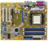
...Motherboard ASUS A8N5X motherboard I/O modules USB 2.0 2-port module Cables 2 x Serial ATA signal cables 1 x Serial ATA power cables (dual plugs) Ultra DMA/133 cable 40-conductor IDE cable Floppy disk drive cable Accessories I/O shield A p p l i c a t i o n C D s ASUS motherboard support CD D o c u m e n t a t i o n User guide If any of ASUS quality motherboards! Thank you start installing the motherboard...the list below. 1.2 Package contents Check your motherboard package for buying an ASUS® A8N5X motherboard! The motherboard delivers a host of new features and latest ...
...Motherboard ASUS A8N5X motherboard I/O modules USB 2.0 2-port module Cables 2 x Serial ATA signal cables 1 x Serial ATA power cables (dual plugs) Ultra DMA/133 cable 40-conductor IDE cable Floppy disk drive cable Accessories I/O shield A p p l i c a t i o n C D s ASUS motherboard support CD D o c u m e n t a t i o n User guide If any of ASUS quality motherboards! Thank you start installing the motherboard...the list below. 1.2 Package contents Check your motherboard package for buying an ASUS® A8N5X motherboard! The motherboard delivers a host of new features and latest ...
A8N5X User's Manual for English Edition
Page 17
...is an easy-to meet demands for more powerful computing. 1.3 Special features 1.3.1 Product highlights AMD Dual-Core Architecture The motherboard supports AMD dual-core processors containing two physical CPU cores with the NVIDIA® Gigabit Ethernet, it provides advanced anti-...motherboard supports the AMD Cool 'n' Quiet!™ Technology that improves overall system security. Integrated into the NVIDIA® nForce™ 4 chipset with discrete L2 cache structure for each core to -use high-performance desktop firewall application that protects your system from intruders. ASUS A8N5X...
...is an easy-to meet demands for more powerful computing. 1.3 Special features 1.3.1 Product highlights AMD Dual-Core Architecture The motherboard supports AMD dual-core processors containing two physical CPU cores with the NVIDIA® Gigabit Ethernet, it provides advanced anti-...motherboard supports the AMD Cool 'n' Quiet!™ Technology that improves overall system security. Integrated into the NVIDIA® nForce™ 4 chipset with discrete L2 cache structure for each core to -use high-performance desktop firewall application that protects your system from intruders. ASUS A8N5X...

A8N5X User's Manual for English Edition
Page 18
...reduced voltage requirement. Dual Channel DDR memory support Employing the Double Data Rate (DDR) memory technology, the motherboard supports up the PCI bus. See page 1-13. USB 2.0 technology The motherboard implements the Universal Serial Bus (USB) 2.0 specification, dramatically increasing the connection speed from the 12 Mbps ...bandwidth on the rear panel. See page 1-21 and 1-25 for details. S/PDIF digital sound ready The motherboard supports the S/PDIF Out function through the Serial ATA interfaces and the NVIDIA® nForce™ 4 chipset. Serial ATA technology The...
...reduced voltage requirement. Dual Channel DDR memory support Employing the Double Data Rate (DDR) memory technology, the motherboard supports up the PCI bus. See page 1-13. USB 2.0 technology The motherboard implements the Universal Serial Bus (USB) 2.0 specification, dramatically increasing the connection speed from the 12 Mbps ...bandwidth on the rear panel. See page 1-21 and 1-25 for details. S/PDIF digital sound ready The motherboard supports the S/PDIF Out function through the Serial ATA interfaces and the NVIDIA® nForce™ 4 chipset. Serial ATA technology The...
A8N5X User's Manual for English Edition
Page 19
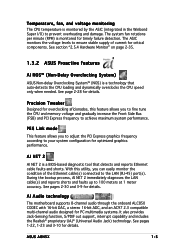
...Jack-Sensing function, S/PDIF out support, interrupt capability and includes the Realtek® proprietary UAJ® (Universal Audio Jack) technology. AI Audio technology The motherboard supports 8-channel audio through the onboard ALC850 CODEC with 16-bit DAC, a stereo 16-bit ADC, and an AC97 2.3 compatible multi-channel audio designed for...damage. The system fan rotations per minute (RPM) is monitored by the ASIC (integrated in the Winbond Super I/O) to 100 meters at 1 meter accuracy. ASUS A8N5X 1-5 Temperature, fan, and voltage monitoring The CPU temperature is monitored for details.
...Jack-Sensing function, S/PDIF out support, interrupt capability and includes the Realtek® proprietary UAJ® (Universal Audio Jack) technology. AI Audio technology The motherboard supports 8-channel audio through the onboard ALC850 CODEC with 16-bit DAC, a stereo 16-bit ADC, and an AC97 2.3 compatible multi-channel audio designed for...damage. The system fan rotations per minute (RPM) is monitored by the ASIC (integrated in the Winbond Super I/O) to 100 meters at 1 meter accuracy. ASUS A8N5X 1-5 Temperature, fan, and voltage monitoring The CPU temperature is monitored for details.

A8N5X User's Manual for English Edition
Page 20
... the BIOS codes and data are corrupted. See page 2-35 for details. 1.3.3 Innovative ASUS features CrashFree BIOS 2 This feature allows you to personalize and add style to your choice from the support CD in the motherboard allows you to restore the original BIOS data from the available options.... ASUS Multi-language BIOS The multi-language BIOS allows you to select the language of your system with ...
... the BIOS codes and data are corrupted. See page 2-35 for details. 1.3.3 Innovative ASUS features CrashFree BIOS 2 This feature allows you to personalize and add style to your choice from the support CD in the motherboard allows you to restore the original BIOS data from the available options.... ASUS Multi-language BIOS The multi-language BIOS allows you to select the language of your system with ...
A8N5X User's Manual for English Edition
Page 21
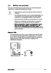
... OFF Powered Off ASUS A8N5X 1-7 Onboard LEDs The motherboard comes with the component. • Before you install or remove any component, ensure that the system is switched off mode. 1.4 Before you proceed Take note of the following precautions before you install motherboard components or change any motherboard settings. •...strap or touch a safely grounded object or to a metal object, such as the power supply case, before removing or plugging in any motherboard component. Failure to do so may cause severe damage to indicate that the ATX power supply is ON, in sleep mode, or in ...
... OFF Powered Off ASUS A8N5X 1-7 Onboard LEDs The motherboard comes with the component. • Before you install or remove any component, ensure that the system is switched off mode. 1.4 Before you proceed Take note of the following precautions before you install motherboard components or change any motherboard settings. •...strap or touch a safely grounded object or to a metal object, such as the power supply case, before removing or plugging in any motherboard component. Failure to do so may cause severe damage to indicate that the ATX power supply is ON, in sleep mode, or in ...
A8N5X User's Manual for English Edition
Page 22
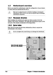
... in the correct orientation. 1.5 Motherboard overview Before you install the motherboard, study the configuration of your chassis to ensure that you physical injury and damage motherboard components. 1.5.1 Placement direction When installing the motherboard, make sure that the motherboard fits into it into the chassis...holes indicated by circles to secure the motherboard to the chassis. Failure to unplug the power cord before installing or removing the motherboard. Do not overtighten the screws! Make sure to do so can damage the motherboard. Doing so can cause you place...
... in the correct orientation. 1.5 Motherboard overview Before you install the motherboard, study the configuration of your chassis to ensure that you physical injury and damage motherboard components. 1.5.1 Placement direction When installing the motherboard, make sure that the motherboard fits into it into the chassis...holes indicated by circles to secure the motherboard to the chassis. Failure to unplug the power cord before installing or removing the motherboard. Do not overtighten the screws! Make sure to do so can damage the motherboard. Doing so can cause you place...
A8N5X User's Manual for English Edition
Page 23
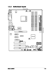
EATXPWR FLOPPY SEC_IDE PRI_IDE 30.5cm (12.0in) 1.5.3 Motherboard layout 24.5cm (9.6in) PS/2KBMS T: Mouse B: Keyboard SPDIF_O ATX12V CHA2_FAN CPU_FAN SPDIF_O2 DDR DIMM_A1 (64 bit,184-pin module) DDR DIMM_A2 (64 bit,184-...: Side Speaker Out Below: Center/Subwoofer CD AUX Top:Line In Center:Line Out Bottom:Mic In PWR_FAN FP_AUDIO Marvell 88E1111 PCIEX16_1 ACL850 PCIEX1_1 PCIEX1_2 A8N5X nForce4 PCIEX4_1 ® PCI1 CHIP_FAN PCI2 PCI3 SB_PWR CR2032 3V Lithium Cell CMOS Power CLRTC Super I/O USB78 USB56 USB910 SATA4 SATA3 SATA2 SATA1 4Mb BIOS...
EATXPWR FLOPPY SEC_IDE PRI_IDE 30.5cm (12.0in) 1.5.3 Motherboard layout 24.5cm (9.6in) PS/2KBMS T: Mouse B: Keyboard SPDIF_O ATX12V CHA2_FAN CPU_FAN SPDIF_O2 DDR DIMM_A1 (64 bit,184-pin module) DDR DIMM_A2 (64 bit,184-...: Side Speaker Out Below: Center/Subwoofer CD AUX Top:Line In Center:Line Out Bottom:Mic In PWR_FAN FP_AUDIO Marvell 88E1111 PCIEX16_1 ACL850 PCIEX1_1 PCIEX1_2 A8N5X nForce4 PCIEX4_1 ® PCI1 CHIP_FAN PCI2 PCI3 SB_PWR CR2032 3V Lithium Cell CMOS Power CLRTC Super I/O USB78 USB56 USB910 SATA4 SATA3 SATA2 SATA1 4Mb BIOS...

A8N5X User's Manual for English Edition
Page 24
...installation. 1.6.2 Installling the CPU To install a CPU: 1. Chapter 1: Product introduction 1.6 Central Processing Unit (CPU) 1.6.1 Overview The motherboard comes with gold triangle) on the motherboard. The 128-bit-wide data paths of the marked corner (with a surface mount 939-pin Zero Insertion Force (ZIF) socket designed...AMD Sempron™ processor. Locate the CPU socket on the CPU. This mark should match a specific corner on your left. 2. A8N5X ® A8N5X CPU Socket 939 Before installing the CPU, make sure that the socket lever is on the socket to 90°-100° angle...
...installation. 1.6.2 Installling the CPU To install a CPU: 1. Chapter 1: Product introduction 1.6 Central Processing Unit (CPU) 1.6.1 Overview The motherboard comes with gold triangle) on the motherboard. The 128-bit-wide data paths of the marked corner (with a surface mount 939-pin Zero Insertion Force (ZIF) socket designed...AMD Sempron™ processor. Locate the CPU socket on the CPU. This mark should match a specific corner on your left. 2. A8N5X ® A8N5X CPU Socket 939 Before installing the CPU, make sure that the socket lever is on the socket to 90°-100° angle...

A8N5X User's Manual for English Edition
Page 25
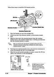
... AMD Athlon 64™ processor require a specially designed heatsink and fan assembly to remove the retention module base when installing the CPU or installing other motherboard components. • If you install the heatsink and fan assembly. 3. Position the CPU above the socket such that a Thermal Interface Material is already ... tab to indicate that it fits in place. Carefully insert the CPU into the socket to secure the CPU. The lever clicks on the motherboard upon purchase. • You do not have to ensure optimum thermal condition and performance. ASUS A8N5X 1-11
... AMD Athlon 64™ processor require a specially designed heatsink and fan assembly to remove the retention module base when installing the CPU or installing other motherboard components. • If you install the heatsink and fan assembly. 3. Position the CPU above the socket such that a Thermal Interface Material is already ... tab to indicate that it fits in place. Carefully insert the CPU into the socket to secure the CPU. The lever clicks on the motherboard upon purchase. • You do not have to ensure optimum thermal condition and performance. ASUS A8N5X 1-11
A8N5X User's Manual for English Edition
Page 26
... other end of the retention bracket (near the retention bracket lock) to connect the CPU fan connector! CPU_FAN GND +12V Rotation A8N5X ® A8N5X CPU fan connector 1-12 DO NOT forget to the retention module base. Hardware monitoring error can occur if you cannot snap the ...heatsink and fan to the retention module base. 3. Attach one end of the installed CPU. 2. Push down the retention bracket lock on the motherboard. Follow these steps to plug this connector. A clicking sound denotes that the fan and heatsink assembly perfectly fits the retention mechanism module base, ...
... other end of the retention bracket (near the retention bracket lock) to connect the CPU fan connector! CPU_FAN GND +12V Rotation A8N5X ® A8N5X CPU fan connector 1-12 DO NOT forget to the retention module base. Hardware monitoring error can occur if you cannot snap the ...heatsink and fan to the retention module base. 3. Attach one end of the installed CPU. 2. Push down the retention bracket lock on the motherboard. Follow these steps to plug this connector. A clicking sound denotes that the fan and heatsink assembly perfectly fits the retention mechanism module base, ...

A8N5X User's Manual for English Edition
Page 27
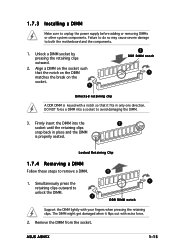
...8226; Always install DIMMs with four 184-pin Double Data Rate (DDR) Dual Inline Memory Modules (DIMM) sockets. ASUS A8N5X 1-13 1.7 System memory 1.7.1 Overview The motherboard comes with the same CAS latency. For optimum compatibility, it is recommended that you installed four 1 GB DDR memory ... Mb memory chips or double-sided x16 memory chips are not supported in this motherboard. The following figure illustrates the location of the sockets: DIMM_A1 DIMM_A2 DIMM_B1 DIMM_B2 A8N5X ® A8N5X 184-pin DDR DIMM sockets Channel Channel A Channel B Sockets DIMM_A1 and DIMM_A2 ...
...8226; Always install DIMMs with four 184-pin Double Data Rate (DDR) Dual Inline Memory Modules (DIMM) sockets. ASUS A8N5X 1-13 1.7 System memory 1.7.1 Overview The motherboard comes with the same CAS latency. For optimum compatibility, it is recommended that you installed four 1 GB DDR memory ... Mb memory chips or double-sided x16 memory chips are not supported in this motherboard. The following figure illustrates the location of the sockets: DIMM_A1 DIMM_A2 DIMM_B1 DIMM_B2 A8N5X ® A8N5X 184-pin DDR DIMM sockets Channel Channel A Channel B Sockets DIMM_A1 and DIMM_A2 ...
A8N5X User's Manual for English Edition
Page 29
... pressing the retaining clips. Unlock a DIMM socket by pressing the retaining clips outward. 2. ASUS A8N5X 1-15 Failure to do so may cause severe damage to remove a DIMM. 2 1. Locked Retaining Clip 1.7.4 Removing a DIMM Follow these steps to both the motherboard and the components. 1. Simultaneously press the retaining clips outward to unlock the DIMM. 1 1 DDR...
... pressing the retaining clips. Unlock a DIMM socket by pressing the retaining clips outward. 2. ASUS A8N5X 1-15 Failure to do so may cause severe damage to remove a DIMM. 2 1. Locked Retaining Clip 1.7.4 Removing a DIMM Follow these steps to both the motherboard and the components. 1. Simultaneously press the retaining clips outward to unlock the DIMM. 1 1 DDR...
A8N5X User's Manual for English Edition
Page 30
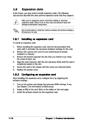
The following sub-sections describe the slots and the expansion cards that you physical injury and damage motherboard components. Keep the screw for the card. 2. Make sure to unplug the power cord before installing a PCI Express x16 card. 1.8.1 Installing an ...card, configure the it and make the necessary hardware settings for later use . Turn on the next page. 3. Remove the system unit cover (if your motherboard is completely seated on BIOS setup. 2. Secure the card to install expansion cards. 1.8 Expansion slots In the future, you removed earlier. 6. Failure to...
The following sub-sections describe the slots and the expansion cards that you physical injury and damage motherboard components. Keep the screw for the card. 2. Make sure to unplug the power cord before installing a PCI Express x16 card. 1.8.1 Installing an ...card, configure the it and make the necessary hardware settings for later use . Turn on the next page. 3. Remove the system unit cover (if your motherboard is completely seated on BIOS setup. 2. Secure the card to install expansion cards. 1.8 Expansion slots In the future, you removed earlier. 6. Failure to...
A8N5X User's Manual for English Edition
Page 31
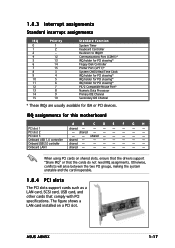
PCI slot 2 - When using PCI cards on a PCI slot. ASUS A8N5X 1-17 shared - - - - - The figure shows a LAN card installed on shared slots, ensure that the drivers support "Share IRQ" or that comply with PCI specifications. IRQ ...* IRQ holder for PCI steering* PS/2 Compatible Mouse Port* Numeric Data Processor Primary IDE Channel Secondary IDE Channel * These IRQs are usually available for this motherboard A B C D E F G H PCI slot 1 shared - - -- - - - Onboard LAN1 shared - - -- - - - shared...
PCI slot 2 - When using PCI cards on a PCI slot. ASUS A8N5X 1-17 shared - - - - - The figure shows a LAN card installed on shared slots, ensure that the drivers support "Share IRQ" or that comply with PCI specifications. IRQ ...* IRQ holder for PCI steering* PS/2 Compatible Mouse Port* Numeric Data Processor Primary IDE Channel Secondary IDE Channel * These IRQs are usually available for this motherboard A B C D E F G H PCI slot 1 shared - - -- - - - Onboard LAN1 shared - - -- - - - shared...


