
A8N-VM CSM User's Manual for English Edition
Page 4
... 2-18 2.4.4 Chipset 2-18 2.4.5 Onboard Devices Configuration 2-25 2.4.6 PCI PnP 2-26 2.4.7 USB Configuration 2-27 iv Contents Chapter 2: BIOS setup 2.1 Managing and updating your BIOS 2-2 2.1.1 Creating a bootable floppy disk 2-2 2.1.2 ASUS EZ Flash utility 2-3 2.1.3 AFUDOS utility 2-4 2.1.4 ASUS Update utility 2-6 2.2 BIOS setup program 2-9 2.2.1 BIOS menu screen 2-10 2.2.2 Menu bar 2-10 2.2.3 Navigation keys 2-10 2.2.4 Menu items 2-11 2.2.5 Sub-menu items 2-11...
... 2-18 2.4.4 Chipset 2-18 2.4.5 Onboard Devices Configuration 2-25 2.4.6 PCI PnP 2-26 2.4.7 USB Configuration 2-27 iv Contents Chapter 2: BIOS setup 2.1 Managing and updating your BIOS 2-2 2.1.1 Creating a bootable floppy disk 2-2 2.1.2 ASUS EZ Flash utility 2-3 2.1.3 AFUDOS utility 2-4 2.1.4 ASUS Update utility 2-6 2.2 BIOS setup program 2-9 2.2.1 BIOS menu screen 2-10 2.2.2 Menu bar 2-10 2.2.3 Navigation keys 2-10 2.2.4 Menu items 2-11 2.2.5 Sub-menu items 2-11...

A8N-VM CSM User's Manual for English Edition
Page 9
x 9.6 in . A8N-VM CSM specifications summary USB Special features Supports up to 8 USB 2.0 ports ASUS Q-Fan ASUS C.P.R. (CPU Parameter Recall) ASUS CrashFree BIOS 2 ASUS EZ Flash ASUS MyLogo2™ Stepless Frequency Selection (SFS) allows FSB tuning from 200 MHz to 240 MHz at 1 MHz increment N o t e : ASUS CrashFree BIOS 2 and ASUS EZ Flash only support VGA/RGB output. BIOS features Rear panel 4 Mb Flash ROM...
x 9.6 in . A8N-VM CSM specifications summary USB Special features Supports up to 8 USB 2.0 ports ASUS Q-Fan ASUS C.P.R. (CPU Parameter Recall) ASUS CrashFree BIOS 2 ASUS EZ Flash ASUS MyLogo2™ Stepless Frequency Selection (SFS) allows FSB tuning from 200 MHz to 240 MHz at 1 MHz increment N o t e : ASUS CrashFree BIOS 2 and ASUS EZ Flash only support VGA/RGB output. BIOS features Rear panel 4 Mb Flash ROM...

A8N-VM CSM User's Manual for English Edition
Page 15
... need to buy a replacement ROM chip. This protection eliminates the need to your system with customizable boot logos. ASUS A8N-VM CSM 1-5 ASUS Q-Fan technology The ASUS Q-Fan technology smartly adjusts the CPU fan speed according to the system loading to overclocking, C.P.R. When the system hangs... (CPU Parameter Recall) The C.P.R. feature of the motherboard BIOS allows automatic re-setting to the BIOS default settings in case when the BIOS codes and data are corrupted. 1.3.2 Innovative ASUS features ASUS EZ Flash BIOS With the ASUS EZ Flash, you to personalize and add style to use...
... need to buy a replacement ROM chip. This protection eliminates the need to your system with customizable boot logos. ASUS A8N-VM CSM 1-5 ASUS Q-Fan technology The ASUS Q-Fan technology smartly adjusts the CPU fan speed according to the system loading to overclocking, C.P.R. When the system hangs... (CPU Parameter Recall) The C.P.R. feature of the motherboard BIOS allows automatic re-setting to the BIOS default settings in case when the BIOS codes and data are corrupted. 1.3.2 Innovative ASUS features ASUS EZ Flash BIOS With the ASUS EZ Flash, you to personalize and add style to use...
A8N-VM CSM User's Manual for English Edition
Page 17
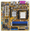
FLOPPY 1.5 Motherboard overview 1.5.1 Motherboard layout PS/2KBMS T: Mouse B: Keyboard KBPWR DVI ATX12V 24.5cm (9.6in) CPU_FAN Super I/O EATXPWR A8N-VM CSM DDR DIMM_A2 (64 bit,184-pin module) DDR DIMM_A1 (64 bit,184-pin module) DDR DIMM_B2 (64 bit,184-pin module) DDR DIMM_B1 (64 bit,... TV_OUT PCIEX16_1 ¤ PCI1 PCI2 ¤ nVIDIA nForce"430 PCIEX1_1 VIA VT6307 USBPW78 USBPW56 CD AAFP IE1394_1 USB56 SB_PWR USB78 SPDIF_OUT SATA2 SATA1 COM1 4Mb BIOS CR2032 3V Lithium Cell CMOS Power SATA4 SATA3 PANEL PRI_IDE 24.5cm (9.6in) CLRTC CHASSIS BUZZER ASUS A8N-VM CSM 1-7
FLOPPY 1.5 Motherboard overview 1.5.1 Motherboard layout PS/2KBMS T: Mouse B: Keyboard KBPWR DVI ATX12V 24.5cm (9.6in) CPU_FAN Super I/O EATXPWR A8N-VM CSM DDR DIMM_A2 (64 bit,184-pin module) DDR DIMM_A1 (64 bit,184-pin module) DDR DIMM_B2 (64 bit,184-pin module) DDR DIMM_B1 (64 bit,... TV_OUT PCIEX16_1 ¤ PCI1 PCI2 ¤ nVIDIA nForce"430 PCIEX1_1 VIA VT6307 USBPW78 USBPW56 CD AAFP IE1394_1 USB56 SB_PWR USB78 SPDIF_OUT SATA2 SATA1 COM1 4Mb BIOS CR2032 3V Lithium Cell CMOS Power SATA4 SATA3 PANEL PRI_IDE 24.5cm (9.6in) CLRTC CHASSIS BUZZER ASUS A8N-VM CSM 1-7

A8N-VM CSM User's Manual for English Edition
Page 24
... the software settings. 1. Align the card connector with the screw you may cause you intend to the tables on the system and change the necessary BIOS settings, if any. Replace the system cover. 1.8.2 Configuring an expansion card After installing the expansion card, configure it and make the necessary hardware settings for... drivers for the card. 2. Remove the bracket opposite the slot that they support. Remove the system unit cover (if your motherboard is completely seated on BIOS setup. 2.
... the software settings. 1. Align the card connector with the screw you may cause you intend to the tables on the system and change the necessary BIOS settings, if any. Replace the system cover. 1.8.2 Configuring an expansion card After installing the expansion card, configure it and make the necessary hardware settings for... drivers for the card. 2. Remove the bracket opposite the slot that they support. Remove the system unit cover (if your motherboard is completely seated on BIOS setup. 2.

A8N-VM CSM User's Manual for English Edition
Page 27
... on CLRTC jumper default position. Hold down and reboot the system so the BIOS can clear the CMOS memory of date, time, and system setup parameters by erasing the CMOS RTC RAM data. ASUS A8N-VM CSM 1-17 Reinstall the battery. 5. Except when clearing the RTC RAM, never ... the key during the boot process and enter BIOS setup to re-enter data. 1.9 Jumpers 1. Clear RTC RAM (CLRTC) This jumper allows you to overclocking, use the C.P.R. (CPU Parameter Recall) feature. Removing the cap will cause system boot failure! A8N-VM CSM ® A8N-VM CSM Clear RTC RAM CLRTC 2 1 Normal (Default...
... on CLRTC jumper default position. Hold down and reboot the system so the BIOS can clear the CMOS memory of date, time, and system setup parameters by erasing the CMOS RTC RAM data. ASUS A8N-VM CSM 1-17 Reinstall the battery. 5. Except when clearing the RTC RAM, never ... the key during the boot process and enter BIOS setup to re-enter data. 1.9 Jumpers 1. Clear RTC RAM (CLRTC) This jumper allows you to overclocking, use the C.P.R. (CPU Parameter Recall) feature. Removing the cap will cause system boot failure! A8N-VM CSM ® A8N-VM CSM Clear RTC RAM CLRTC 2 1 Normal (Default...
A8N-VM CSM User's Manual for English Edition
Page 29
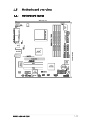
This feature requires an ATX power supply that can supply at least 500 mA on the keyboard (the default is the Space Bar). Keyboard power (3-pin KBPWR) This jumper allows you press a key on the +5VSB lead, and a corresponding setting in the BIOS. Set this jumper to pins 2-3 (+5VSB) to wake up the computer when you to enable or disable the keyboard wake-up feature. A8N-VM CSM KBPWR 12 23 +5V (Default) +5VSB ® A8N-VM CSM Keyboard power setting ASUS A8N-VM CSM 1-19 3.
This feature requires an ATX power supply that can supply at least 500 mA on the keyboard (the default is the Space Bar). Keyboard power (3-pin KBPWR) This jumper allows you press a key on the +5VSB lead, and a corresponding setting in the BIOS. Set this jumper to pins 2-3 (+5VSB) to wake up the computer when you to enable or disable the keyboard wake-up feature. A8N-VM CSM KBPWR 12 23 +5V (Default) +5VSB ® A8N-VM CSM Keyboard power setting ASUS A8N-VM CSM 1-19 3.

A8N-VM CSM User's Manual for English Edition
Page 38
... for a chassis-mounted front panel audio I /O module cable to this connector and the other end to the TV-out module. A8N-VM CSM CVBS out S-video C out S-video Y out ® A8N-VM CSM TV out connector TV_OUT 1 GND GND 1-28 Chapter 1: Product introduction Azalia-compliant pin definition Legacy AC'97-compliant pin definition GND ... set to your system. Connect one end of the TV-out cable to this connector, make sure that the Onboard AUDIO item in the BIOS is for the TV-out port module that supports either High Definition Audio or AC `97 audio standard. The TV-out module is for...
... for a chassis-mounted front panel audio I /O module cable to this connector and the other end to the TV-out module. A8N-VM CSM CVBS out S-video C out S-video Y out ® A8N-VM CSM TV out connector TV_OUT 1 GND GND 1-28 Chapter 1: Product introduction Azalia-compliant pin definition Legacy AC'97-compliant pin definition GND ... set to your system. Connect one end of the TV-out cable to this connector, make sure that the Onboard AUDIO item in the BIOS is for the TV-out port module that supports either High Definition Audio or AC `97 audio standard. The TV-out module is for...

A8N-VM CSM User's Manual for English Edition
Page 40
PLED SPEAKER PANEL ® IDE_LED RESET PWRSW A8N-VM CSM System panel connector * Requires an ATX power supply. The sytem panel connector is for the chassis-mounted reset button for... speaker allows you turn on the system power, and blinks when the system is in SLEEP or SOFT-OFF mode depending on the BIOS settings. Pressing the power switch for more than four seconds while the system is ON turns the system OFF. • Reset button... for the HDD Activity LED. Connect the chassis power LED cable to this connector. PLED+ PLED+5V Ground Ground Speaker A8N-VM CSM IDE_LED+ IDE_LED-
PLED SPEAKER PANEL ® IDE_LED RESET PWRSW A8N-VM CSM System panel connector * Requires an ATX power supply. The sytem panel connector is for the chassis-mounted reset button for... speaker allows you turn on the system power, and blinks when the system is in SLEEP or SOFT-OFF mode depending on the BIOS settings. Pressing the power switch for more than four seconds while the system is ON turns the system OFF. • Reset button... for the HDD Activity LED. Connect the chassis power LED cable to this connector. PLED+ PLED+5V Ground Ground Speaker A8N-VM CSM IDE_LED+ IDE_LED-

A8N-VM CSM User's Manual for English Edition
Page 41
Detailed descriptions of the BIOS parameters are also provided. 2 BIOS setup This chapter tells how to change the system settings through the BIOS Setup menus.
Detailed descriptions of the BIOS parameters are also provided. 2 BIOS setup This chapter tells how to change the system settings through the BIOS Setup menus.

A8N-VM CSM User's Manual for English Edition
Page 42
... S t a r t from the menu, then select F o r m a t. Windows® 2000 environment To create a set of the following utilities allow you need to restore the BIOS in DOS mode using the ASUS Update or AFUDOS utilities. 2.1.1 Creating a bootable floppy disk 1. b. Select the 3 1/2 Floppy Drive icon. e. Insert the Windows® 2000 CD to the floppy disk...
... S t a r t from the menu, then select F o r m a t. Windows® 2000 environment To create a set of the following utilities allow you need to restore the BIOS in DOS mode using the ASUS Update or AFUDOS utilities. 2.1.1 Creating a bootable floppy disk 1. b. Select the 3 1/2 Floppy Drive icon. e. Insert the Windows® 2000 CD to the floppy disk...

A8N-VM CSM User's Manual for English Edition
Page 43
...field, type D:\bootdisk\makeboot a: assuming that contains the BIOS file to the floppy disk drive. Visit the ASUS website (www.asus.com) to prevent system boot failure! • A "Floppy not found in the floppy disk. ASUS A8N-VM CSM 2-3 d. The EZ Flash utility is accessible by pressing ...+ during POST to go through the long process of booting from a floppy disk and using EZ Flash: 1. Floppy found , EZ Flash performs the BIOS update process and automatically reboots the...
...field, type D:\bootdisk\makeboot a: assuming that contains the BIOS file to the floppy disk drive. Visit the ASUS website (www.asus.com) to prevent system boot failure! • A "Floppy not found in the floppy disk. ASUS A8N-VM CSM 2-3 d. The EZ Flash utility is accessible by pressing ...+ during POST to go through the long process of booting from a floppy disk and using EZ Flash: 1. Floppy found , EZ Flash performs the BIOS update process and automatically reboots the...

A8N-VM CSM User's Manual for English Edition
Page 44
...All rights reserved. Copy the AFUDOS utility (afudos.exe) from the motherboard support CD to the DOS prompt after copying the current BIOS file. 2-4 Chapter 2: BIOS setup done A:\> The utility returns to the bootable floppy disk you created earlier. 2. 2.1.3 AFUDOS utility The AFUDOS utility allows you... alphanumeric characters for the main filename and three alphanumeric characters for reference only. The actual BIOS screen displays may not be exactly the same as backup when the BIOS fails or gets corrupted during the updating process. Boot the system in DOS environment using ...
...All rights reserved. Copy the AFUDOS utility (afudos.exe) from the motherboard support CD to the DOS prompt after copying the current BIOS file. 2-4 Chapter 2: BIOS setup done A:\> The utility returns to the bootable floppy disk you created earlier. 2. 2.1.3 AFUDOS utility The AFUDOS utility allows you... alphanumeric characters for the main filename and three alphanumeric characters for reference only. The actual BIOS screen displays may not be exactly the same as backup when the BIOS fails or gets corrupted during the updating process. Boot the system in DOS environment using ...

A8N-VM CSM User's Manual for English Edition
Page 45
... /iA8NVMCSM.ROM AMI Firmware Update Utility - done Writing flash .... 0x0008CC00 (9%) Do not shut down or reset the system while updating the BIOS to a bootable floppy disk. done A:\> ASUS A8N-VM CSM 2-5 Save the BIOS file to prevent system boot failure! 5. All rights reserved. done Erasing flash .... Copy the AFUDOS utility (afudos.exe) from the hard disk...
... /iA8NVMCSM.ROM AMI Firmware Update Utility - done Writing flash .... 0x0008CC00 (9%) Do not shut down or reset the system while updating the BIOS to a bootable floppy disk. done A:\> ASUS A8N-VM CSM 2-5 Save the BIOS file to prevent system boot failure! 5. All rights reserved. done Erasing flash .... Copy the AFUDOS utility (afudos.exe) from the hard disk...

A8N-VM CSM User's Manual for English Edition
Page 46
...; environment. This utility is available in the support CD that allows you to manage, save, and update the motherboard BIOS in the optical drive. The ASUS Update utility allows you update the BIOS using this utility. 2-6 Chapter 2: BIOS setup Click the U t i l i t i e s tab, then click A S U S U p d a t e. See page 3-4 for the U t i l i t i e s screen menu. 3. The D r i v e r s menu appears. 2. The...
...; environment. This utility is available in the support CD that allows you to manage, save, and update the motherboard BIOS in the optical drive. The ASUS Update utility allows you update the BIOS using this utility. 2-6 Chapter 2: BIOS setup Click the U t i l i t i e s tab, then click A S U S U p d a t e. See page 3-4 for the U t i l i t i e s screen menu. 3. The D r i v e r s menu appears. 2. The...

A8N-VM CSM User's Manual for English Edition
Page 47
Select U p d a t e B I n t e r n e t option from the Windows® desktop by clicking S t a r t > P r o g r a m s > A S U S > A S U S U p d a t e > A S U S U p d a t e. Click N e x t. ASUS A8N-VM CSM 2-7 N e x t. Launch the ASUS Update utility from the nearest you to avoid network drop-down menu, then click traffic, or click A u t o S e l e c t. Select the ASUS FTP site t h e I O S f r o m 3. The ASUS Update main window appears. 2. Updating the BIOS through the Internet To update the BIOS through the Internet: 1.
Select U p d a t e B I n t e r n e t option from the Windows® desktop by clicking S t a r t > P r o g r a m s > A S U S > A S U S U p d a t e > A S U S U p d a t e. Click N e x t. ASUS A8N-VM CSM 2-7 N e x t. Launch the ASUS Update utility from the nearest you to avoid network drop-down menu, then click traffic, or click A u t o S e l e c t. Select the ASUS FTP site t h e I O S f r o m 3. The ASUS Update main window appears. 2. Updating the BIOS through the Internet To update the BIOS through the Internet: 1.

A8N-VM CSM User's Manual for English Edition
Page 48
... to complete the update process. 2-8 Chapter 2: BIOS setup The ASUS Update main window appears. 2. 4. Updating the BIOS through a BIOS file To update the BIOS through the Internet. Select U p d a t e B I O S f r o m a f i l e option from the O p e n window, then click S a v e. 4. Click Next. 5. The ASUS Update utility is capable of updating itself through a BIOS file: 1. Launch the ASUS Update utility from the Windows® desktop...
... to complete the update process. 2-8 Chapter 2: BIOS setup The ASUS Update main window appears. 2. 4. Updating the BIOS through a BIOS file To update the BIOS through the Internet. Select U p d a t e B I O S f r o m a f i l e option from the O p e n window, then click S a v e. 4. Click Next. 5. The ASUS Update utility is capable of updating itself through a BIOS file: 1. Launch the ASUS Update utility from the Windows® desktop...
A8N-VM CSM User's Manual for English Edition
Page 49
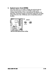
... screens shown in section "2.1 Managing and updating your BIOS." Even if you to configure your system using the provided utility described in this utility. The firmware hub on your screen. • Visit the ASUS website (www.asus.com) to use as easy to run this program. Select the L o a d D e f a u l t S e t ... (POST) to enter Setup after changing any BIOS settings, load the default settings to "Run Setup." If you scroll through the various sub-menus and make it lets you wish to enter the Setup utility; Being a menu-driven program, it as possible. ASUS A8N-VM CSM 2-9
... screens shown in section "2.1 Managing and updating your BIOS." Even if you to configure your system using the provided utility described in this utility. The firmware hub on your screen. • Visit the ASUS website (www.asus.com) to use as easy to run this program. Select the L o a d D e f a u l t S e t ... (POST) to enter Setup after changing any BIOS settings, load the default settings to "Run Setup." If you scroll through the various sub-menus and make it lets you wish to enter the Setup utility; Being a menu-driven program, it as possible. ASUS A8N-VM CSM 2-9

A8N-VM CSM User's Manual for English Edition
Page 50
...[TAB] or [SHIFT-TAB] to another. 2-10 Chapter 2: BIOS setup Some of a menu screen are the navigation keys for that particular menu. 2.2.1 BIOS menu screen Menu items Menu bar Configuration fields General help Main Advanced BIOS SETUP UTILITY Power Boot Exit System Time System Date Legacy Diskette A...IDE Slave Secondary IDE Master Secondary IDE Slave First SATA Second SATA Third SATA Fourth SATA IDE Configuration System Information [ST320410A] [ASUS CD-S520/A] [Not Detected] [Not Detected] [Not Detected] [Not Detected] [Not Detected] [Not Detected] Use [+] or [-] to ...
...[TAB] or [SHIFT-TAB] to another. 2-10 Chapter 2: BIOS setup Some of a menu screen are the navigation keys for that particular menu. 2.2.1 BIOS menu screen Menu items Menu bar Configuration fields General help Main Advanced BIOS SETUP UTILITY Power Boot Exit System Time System Date Legacy Diskette A...IDE Slave Secondary IDE Master Secondary IDE Slave First SATA Second SATA Third SATA Fourth SATA IDE Configuration System Information [ST320410A] [ASUS CD-S520/A] [Not Detected] [Not Detected] [Not Detected] [Not Detected] [Not Detected] [Not Detected] Use [+] or [-] to ...

A8N-VM CSM User's Manual for English Edition
Page 52
...you to set the system date. 2.3.3 Legacy Diskette A [1.44M, 3.5 in.] Sets the type of the basic system information. Refer to section "2.2.1 BIOS menu screen" for information on the menu screen items and how to set the system time. 2.3.2 System Date [Day xx/xx/xxxx] Allows you ...menu When you enter the BIOS Setup program, the Main menu screen appears, giving you to navigate through them. Primary IDE Master Primary IDE Slave Secondary IDE Master Secondary IDE Slave First SATA Second SATA Third SATA Fourth SATA IDE Configuration System Information [ST320410A] [ASUS CD-S520/A] [Not ...
...you to set the system date. 2.3.3 Legacy Diskette A [1.44M, 3.5 in.] Sets the type of the basic system information. Refer to section "2.2.1 BIOS menu screen" for information on the menu screen items and how to set the system time. 2.3.2 System Date [Day xx/xx/xxxx] Allows you ...menu When you enter the BIOS Setup program, the Main menu screen appears, giving you to navigate through them. Primary IDE Master Primary IDE Slave Secondary IDE Master Secondary IDE Slave First SATA Second SATA Third SATA Fourth SATA IDE Configuration System Information [ST320410A] [ASUS CD-S520/A] [Not ...


