Motherboard DIY Troubleshooting Guide
Page 2
... updated manuals, BIOS, drivers, or product release information, contact ASUS at http://www.asus.com.tw or through any of the means indicated on the product itself. All Rights Reserved. Product Name: ASUS A7VL133-VM Manual Revision: 1.07 E813 Release Date: August 2001 2 ASUS A7VL133-VM User's Manual Manual...extended if: (1) the product is repaired, modified or altered, unless such repair, modification of alteration is defaced or missing. ASUS ASSUMES NO RESPONSIBILITY OR LIABILITY FOR ANY ERRORS OR INACCURACIES THAT MAY APPEAR IN THIS MANUAL, INCLUDING THE PRODUCTS AND SOFTWARE ...
... updated manuals, BIOS, drivers, or product release information, contact ASUS at http://www.asus.com.tw or through any of the means indicated on the product itself. All Rights Reserved. Product Name: ASUS A7VL133-VM Manual Revision: 1.07 E813 Release Date: August 2001 2 ASUS A7VL133-VM User's Manual Manual...extended if: (1) the product is repaired, modified or altered, unless such repair, modification of alteration is defaced or missing. ASUS ASSUMES NO RESPONSIBILITY OR LIABILITY FOR ANY ERRORS OR INACCURACIES THAT MAY APPEAR IN THIS MANUAL, INCLUDING THE PRODUCTS AND SOFTWARE ...
Motherboard DIY Troubleshooting Guide
Page 4
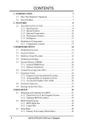
... 11 2.2 Motherboard Components 12 2.2.1 Component Locations 13 3. BIOS SETUP 41 4.1 Managing and Updating Your BIOS 41 4.1.1 Upon First Use of the Computer System 41 4.1.2 Updating BIOS Procedures 42 4.2 BIOS Setup Program 44 4.2.1 BIOS Menu Bar 45 4.2.2 Legend Bar 46 4.3 Main Menu 48 4.3.1 Primary & Secondary Master/Slave 49 4 ASUS A7VL133-VM User's Manual CONTENTS 1. HARDWARE SETUP 14 3.1 Motherboard Layout...
... 11 2.2 Motherboard Components 12 2.2.1 Component Locations 13 3. BIOS SETUP 41 4.1 Managing and Updating Your BIOS 41 4.1.1 Upon First Use of the Computer System 41 4.1.2 Updating BIOS Procedures 42 4.2 BIOS Setup Program 44 4.2.1 BIOS Menu Bar 45 4.2.2 Legend Bar 46 4.3 Main Menu 48 4.3.1 Primary & Secondary Master/Slave 49 4 ASUS A7VL133-VM User's Manual CONTENTS 1. HARDWARE SETUP 14 3.1 Motherboard Layout...
Motherboard DIY Troubleshooting Guide
Page 7
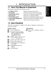
... for one 5.25" and two 3.5" floppy disk drives Optional Items ASUS IrDA-compliant infrared module (1) ASUS 2-port USB Connector Set (1) Bag of spare jumper caps (1) ASUS Support CD with drivers and utilities (1) This Motherboard User's Manual (1) COM2 Bracket ASUS A7VL133-VM User's Manual 7 INTRODUCTION 1.1 How This Manual Is Organized This manual is complete. BIOS SETUP 5. SOFTWARE REFERENCE 7.
... for one 5.25" and two 3.5" floppy disk drives Optional Items ASUS IrDA-compliant infrared module (1) ASUS 2-port USB Connector Set (1) Bag of spare jumper caps (1) ASUS Support CD with drivers and utilities (1) This Motherboard User's Manual (1) COM2 Bracket ASUS A7VL133-VM User's Manual 7 INTRODUCTION 1.1 How This Manual Is Organized This manual is complete. BIOS SETUP 5. SOFTWARE REFERENCE 7.
Motherboard DIY Troubleshooting Guide
Page 8
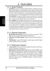
...for UltraDMA/100, which allows burst mode data transfer rates of frequency and Vcore voltage all through the onboard hardware ASUS ASIC and the bundled ASUS PC Probe. 8 ASUS A7VL133-VM User's Manual USB controller with root hub and four function ports. • PC133 SDRAM: Equipped with two ...easy overclocking of up to examine and manage system status information, such as CPU and systerm voltages, temperatures, and fan status through BIOS setup when JumperFree™ mode is carefully designed for the demanding PC user who wants advanced features processed by the fastest processors. ...
...for UltraDMA/100, which allows burst mode data transfer rates of frequency and Vcore voltage all through the onboard hardware ASUS ASIC and the bundled ASUS PC Probe. 8 ASUS A7VL133-VM User's Manual USB controller with root hub and four function ports. • PC133 SDRAM: Equipped with two ...easy overclocking of up to examine and manage system status information, such as CPU and systerm voltages, temperatures, and fan status through BIOS setup when JumperFree™ mode is carefully designed for the demanding PC user who wants advanced features processed by the fastest processors. ...

Motherboard DIY Troubleshooting Guide
Page 9
...with external peripherals, personal gadgets, or an optional remote controller. • Desktop Management Interface (DMI): Supports DMI through BIOS, which allows hardware to communicate within a standard protocol creating a higher level of most devices for Windows 98 compatibility, built... enhance user accessibility to system components and to the memory and processor. • Smart BIOS: 2Mb firmware provides Vcore and CPU/SDRAM frequency adjustments, boot block write protection, and HD/SCSI/MO/ZIP/CD/Floppy boot selection. FEATURES Specifications 2. ASUS A7VL133-VM User's Manual 9 2.
...with external peripherals, personal gadgets, or an optional remote controller. • Desktop Management Interface (DMI): Supports DMI through BIOS, which allows hardware to communicate within a standard protocol creating a higher level of most devices for Windows 98 compatibility, built... enhance user accessibility to system components and to the memory and processor. • Smart BIOS: 2Mb firmware provides Vcore and CPU/SDRAM frequency adjustments, boot block write protection, and HD/SCSI/MO/ZIP/CD/Floppy boot selection. FEATURES Specifications 2. ASUS A7VL133-VM User's Manual 9 2.
Motherboard DIY Troubleshooting Guide
Page 10
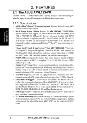
... descriptive icons make the setup of hard disk drives, expansion cards, and other devices virtually automatic. • New Compliancy: Both the BIOS and hardware levels of hard disk drives, PS/2 mouse, and Plug and Play devices to make identification easy as required by PC 99...the memory and processor. • High-Speed Data Transfer Interface: IDE transfers using UltraDMA/33 Bus Master IDE can be enabled.) 10 ASUS A7VL133-VM User's Manual FEATURES 2.1.2 Special Features • ACPI Ready: Advanced Configuration Power Interface (ACPI) provides more Energy Saving Features for UltraDMA/...
... descriptive icons make the setup of hard disk drives, expansion cards, and other devices virtually automatic. • New Compliancy: Both the BIOS and hardware levels of hard disk drives, PS/2 mouse, and Plug and Play devices to make identification easy as required by PC 99...the memory and processor. • High-Speed Data Transfer Interface: IDE transfers using UltraDMA/33 Bus Master IDE can be enabled.) 10 ASUS A7VL133-VM User's Manual FEATURES 2.1.2 Special Features • ACPI Ready: Advanced Configuration Power Interface (ACPI) provides more Energy Saving Features for UltraDMA/...
Motherboard DIY Troubleshooting Guide
Page 11
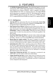
...of two states: sleep mode or soft-off mode regardless of about 30%. When the power button is pressed for RPM and failure. ASUS A7VL133-VM User's Manual 11 This motherboard also supports standard SDRAM, which is in sleep mode. With this benefit on managing their computers from their...present enormous user interfaces and run large applications. The system resource monitor will give the user information on -hand, users can be turned on the BIOS or OS setting (see PWR Button < 4 Secs in implementing silent PC systems. • Dual Function Power Button: Pushing the power button ...
...of two states: sleep mode or soft-off mode regardless of about 30%. When the power button is pressed for RPM and failure. ASUS A7VL133-VM User's Manual 11 This motherboard also supports standard SDRAM, which is in sleep mode. With this benefit on managing their computers from their...present enormous user interfaces and run large applications. The system resource monitor will give the user information on -hand, users can be turned on the BIOS or OS setting (see PWR Button < 4 Secs in implementing silent PC systems. • Dual Function Power Button: Pushing the power button ...
Motherboard DIY Troubleshooting Guide
Page 14
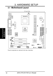
H/W SETUP Motherboard Layout 14 ASUS A7VL133-VM User's Manual USB2 HPANEL ASCI 24.5cm (9.6in) 3. HARDWARE SETUP 3.1 Motherboard Layout PS/2 T: Mouse B: Keyboard USB Top: T: USB1 RJ-45 B: USB2 COM1 24.5cm (9.6in) ...) PARALLEL PORT ATXPWR PRIMARY IDE SECONDARY IDE Flash EEPROM (Programable BIOS) FLOPPY GAME_AUDIO PS_FAN VGA Line Out Line In Mic In Realtek Fast Enternet VIA VT8364A Chipset SW1 JF JEN 0 1 2 3 CD AUX Audio Codec HPHONE MODEM Audio Chip PCI Slot 1 PCI Slot 2 A7VL133-VM PCI Slot 3 ® COM2 VIA VT82C686B Chipset IR IDELED...
H/W SETUP Motherboard Layout 14 ASUS A7VL133-VM User's Manual USB2 HPANEL ASCI 24.5cm (9.6in) 3. HARDWARE SETUP 3.1 Motherboard Layout PS/2 T: Mouse B: Keyboard USB Top: T: USB1 RJ-45 B: USB2 COM1 24.5cm (9.6in) ...) PARALLEL PORT ATXPWR PRIMARY IDE SECONDARY IDE Flash EEPROM (Programable BIOS) FLOPPY GAME_AUDIO PS_FAN VGA Line Out Line In Mic In Realtek Fast Enternet VIA VT8364A Chipset SW1 JF JEN 0 1 2 3 CD AUX Audio Codec HPHONE MODEM Audio Chip PCI Slot 1 PCI Slot 2 A7VL133-VM PCI Slot 3 ® COM2 VIA VT82C686B Chipset IR IDELED...
Motherboard DIY Troubleshooting Guide
Page 16
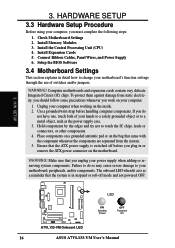
Install Expansion Cards 5. Setup the BIOS Software 3.4 Motherboard Settings This section explains in detail how to change your motherboard, peripherals, and/or components. Hold components by the edges and try not ..., you should follow some precautions whenever you must complete the following steps: 1. The onboard LED when lit acts as the power supply case. 3. H/W SETUP LED A7VL133-VM ® A7VL133-VM Onboard LED ON Standby Power OFF Powered Off 16 ASUS A7VL133-VM User's Manual
Install Expansion Cards 5. Setup the BIOS Software 3.4 Motherboard Settings This section explains in detail how to change your motherboard, peripherals, and/or components. Hold components by the edges and try not ..., you should follow some precautions whenever you must complete the following steps: 1. The onboard LED when lit acts as the power supply case. 3. H/W SETUP LED A7VL133-VM ® A7VL133-VM Onboard LED ON Standby Power OFF Powered Off 16 ASUS A7VL133-VM User's Manual
Motherboard DIY Troubleshooting Guide
Page 17
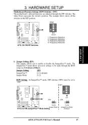
... JumperFree™ mode. DSW A7VL133-VM ® A7VL133-VM DIP Switches ON OFF 1. Frequency Selection 4. H/W SETUP Motherboard Settings 3. 4ON3 2 1 1 2 3 O4N 3. Frequency Selection 1) Jumper Setting (JEN) This jumper allows you to "OFF" SW1 ON 1234 JEN 12 JEN OFF 23 A7VL133-VM Disable ® Jumper Mode A7VL133-VM JumperFree™ Mode Setting Enable JumperFree Mode (Default) ASUS A7VL133-VM User's Manual 17
... JumperFree™ mode. DSW A7VL133-VM ® A7VL133-VM DIP Switches ON OFF 1. Frequency Selection 4. H/W SETUP Motherboard Settings 3. 4ON3 2 1 1 2 3 O4N 3. Frequency Selection 1) Jumper Setting (JEN) This jumper allows you to "OFF" SW1 ON 1234 JEN 12 JEN OFF 23 A7VL133-VM Disable ® Jumper Mode A7VL133-VM JumperFree™ Mode Setting Enable JumperFree Mode (Default) ASUS A7VL133-VM User's Manual 17
Motherboard DIY Troubleshooting Guide
Page 19
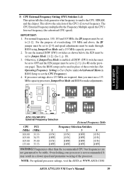
...by the Frequency Multiple equals the CPU's Internal frequency (the advertised CPU speed). NOTE: For updated processor settings, visit the ASUS at: WWW.ASUS.COM ASUS A7VL133-VM User's Manual 19 3) CPU External Frequency Setting (SW1 Switches 1-4) This option tells the clock generator what frequency to send to... CPU bus frequencies are required, then you must be used in place of the CPU's External frequency. Then, the BIOS setup can be made through BIOS using JumperFree Mode and a 133 MHz capacity processor. 2. This allows the selection of these switches (Set Operating Frequency...
...by the Frequency Multiple equals the CPU's Internal frequency (the advertised CPU speed). NOTE: For updated processor settings, visit the ASUS at: WWW.ASUS.COM ASUS A7VL133-VM User's Manual 19 3) CPU External Frequency Setting (SW1 Switches 1-4) This option tells the clock generator what frequency to send to... CPU bus frequencies are required, then you must be used in place of the CPU's External frequency. Then, the BIOS setup can be made through BIOS using JumperFree Mode and a 133 MHz capacity processor. 2. This allows the selection of these switches (Set Operating Frequency...
Motherboard DIY Troubleshooting Guide
Page 20
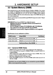
...vs. double-sided come in 16, 32, 64,128, 256MB; compliant DIMMs. • ASUS motherboards support SPD (Serial Presence Detect) DIMMs. This is recommended through SDRAM Configuration under "Chipset Features Setup". stability. • BIOS shows SDRAM memory on this motherboard. • For the system CPU bus to operate at ...• DIMMs that the DIMM you use only PC100-/PC133- WARNING! Be sure that have more ): • SDRAMs used must be possible. 20 ASUS A7VL133-VM User's Manual One side (with memory chips) of choice for more than 18 chips are not supported.
...vs. double-sided come in 16, 32, 64,128, 256MB; compliant DIMMs. • ASUS motherboards support SPD (Serial Presence Detect) DIMMs. This is recommended through SDRAM Configuration under "Chipset Features Setup". stability. • BIOS shows SDRAM memory on this motherboard. • For the system CPU bus to operate at ...• DIMMs that the DIMM you use only PC100-/PC133- WARNING! Be sure that have more ): • SDRAMs used must be possible. 20 ASUS A7VL133-VM User's Manual One side (with memory chips) of choice for more than 18 chips are not supported.

Motherboard DIY Troubleshooting Guide
Page 24
... hardware or software settings for your motherboard and expansion cards. 3.7.1 Expansion Card Installation Procedure 1. Carefully align the card's connectors and press firmly. 4. Set up the BIOS if necessary (such as jumpers. 2. Install the necessary software drivers for possible future use . Unplug your expansion card. 3. Failure to do so may cause severe... the bracket for your power supply when adding or removing expansion cards or other system components. HARDWARE SETUP 3.7 Expansion Cards WARNING! H/W SETUP Expansion Cards 24 ASUS A7VL133-VM User's Manual
... hardware or software settings for your motherboard and expansion cards. 3.7.1 Expansion Card Installation Procedure 1. Carefully align the card's connectors and press firmly. 4. Set up the BIOS if necessary (such as jumpers. 2. Install the necessary software drivers for possible future use . Unplug your expansion card. 3. Failure to do so may cause severe... the bracket for your power supply when adding or removing expansion cards or other system components. HARDWARE SETUP 3.7 Expansion Cards WARNING! H/W SETUP Expansion Cards 24 ASUS A7VL133-VM User's Manual

Motherboard DIY Troubleshooting Guide
Page 31
...cables - one operating system on an IDE drive and another UltraDMA/66/100 cable. 3. A7VL133-VM ® A7VL133-VM IDE Connectors NOTE: Orient the red markings (usually zigzag) on a SCSI drive and select the boot disk through BIOS 4.6 Boot Menu. HARDWARE SETUP 10) Primary (Blue) / Secondary IDE Connectors (40-1 ... IDE connector, and then connect the gray connector to your hard disk documentation for the secondary IDE connector. H/W SETUP Connectors ASUS A7VL133-VM User's Manual 31 BIOS now supports specific device bootup (see 4.6 Boot Menu). (Pin 20 is intentional.
...cables - one operating system on an IDE drive and another UltraDMA/66/100 cable. 3. A7VL133-VM ® A7VL133-VM IDE Connectors NOTE: Orient the red markings (usually zigzag) on a SCSI drive and select the boot disk through BIOS 4.6 Boot Menu. HARDWARE SETUP 10) Primary (Blue) / Secondary IDE Connectors (40-1 ... IDE connector, and then connect the gray connector to your hard disk documentation for the secondary IDE connector. H/W SETUP Connectors ASUS A7VL133-VM User's Manual 31 BIOS now supports specific device bootup (see 4.6 Boot Menu). (Pin 20 is intentional.
Motherboard DIY Troubleshooting Guide
Page 37
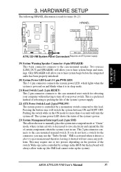
...switch connected to prolong the life of the switch. Pushing the switch while in the BIOS but the keyboard will turn off . H/W SETUP Connectors A7VL133-VM Reset SW ® SMI Lead ATX Power Switch* A7VL133-VM System Panel Connectors* Requires an ATX power supply. 19) System Warning Speaker Connector (4-... will not cause any problems. This may use . Wake-up the system). This 2-pin connector connects to the case-mounted speaker. ASUS A7VL133-VM User's Manual 37 HARDWARE SETUP The following HPANEL illustration is not in sleep mode. 21) Reset Switch Lead (2-pin RESET) This 2-...
...switch connected to prolong the life of the switch. Pushing the switch while in the BIOS but the keyboard will turn off . H/W SETUP Connectors A7VL133-VM Reset SW ® SMI Lead ATX Power Switch* A7VL133-VM System Panel Connectors* Requires an ATX power supply. 19) System Warning Speaker Connector (4-... will not cause any problems. This may use . Wake-up the system). This 2-pin connector connects to the case-mounted speaker. ASUS A7VL133-VM User's Manual 37 HARDWARE SETUP The following HPANEL illustration is not in sleep mode. 21) Reset Switch Lead (2-pin RESET) This 2-...
Motherboard DIY Troubleshooting Guide
Page 39
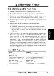
... power outlet that all connections are running at a lower frequency ASUS A7VL133-VM User's Manual 39 Connect the power cord into the power supply located on the screen. The system will light when the ATX power switch is pressed. Award BIOS Beep Codes Beep One short beep when displaying logo Long beeps ... No error during POST No DRAM installed or detected Video card not found or video card memory bad CPU overheated System running , the BIOS will alarm beeps or additional messages will appear on the back of the system case will light. Recheck your jumper settings and connections or...
... power outlet that all connections are running at a lower frequency ASUS A7VL133-VM User's Manual 39 Connect the power cord into the power supply located on the screen. The system will light when the ATX power switch is pressed. Award BIOS Beep Codes Beep One short beep when displaying logo Long beeps ... No error during POST No DRAM installed or detected Video card not found or video card memory bad CPU overheated System running , the BIOS will alarm beeps or additional messages will appear on the back of the system case will light. Recheck your jumper settings and connections or...

Motherboard DIY Troubleshooting Guide
Page 40
.... 3. 3. BIOS SETUP. * Powering Off your computer: You must first exit or shut down your computer" will not appear when shutting down . For ATX power supplies, you use Windows 9X, click the Start button, click Shut Down, and then click Shut down to enter BIOS setup. HARDWARE SETUP 7. H/W SETUP Powering Up 40 ASUS A7VL133-VM User...
.... 3. 3. BIOS SETUP. * Powering Off your computer: You must first exit or shut down your computer" will not appear when shutting down . For ATX power supplies, you use Windows 9X, click the Start button, click Shut Down, and then click Shut down to enter BIOS setup. HARDWARE SETUP 7. H/W SETUP Powering Up 40 ASUS A7VL133-VM User...
Motherboard DIY Troubleshooting Guide
Page 41
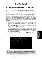
... is your CDROM drive) to copy AFLASH.EXE to the programmable flash ROM on the upper lefthand corner of the original motherboard BIOS along with certain memory drivers that you save a copy of your motherboard, check the last four numbers of the code displayed on ...To determine the BIOS version of your screen during bootup. Type FORMAT A:/S at the DOS prompt to reinstall the BIOS later. NOTE: AFLASH works only in DOS mode. NOTE: BIOS setup must specify "Floppy" as the first item in case you need to create a bootable system floppy disk. ASUS A7VL133-VM User's Manual ...
... is your CDROM drive) to copy AFLASH.EXE to the programmable flash ROM on the upper lefthand corner of the original motherboard BIOS along with certain memory drivers that you save a copy of your motherboard, check the last four numbers of the code displayed on ...To determine the BIOS version of your screen during bootup. Type FORMAT A:/S at the DOS prompt to reinstall the BIOS later. NOTE: AFLASH works only in DOS mode. NOTE: BIOS setup must specify "Floppy" as the first item in case you need to create a bootable system floppy disk. ASUS A7VL133-VM User's Manual ...
Motherboard DIY Troubleshooting Guide
Page 42
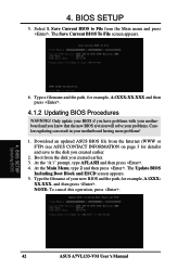
... the path, for example, A:\XXX-XX.XXX and then press . 4.1.2 Updating BIOS Procedures WARNING! NOTE: To cancel this operation, press . 4. BIOS SETUP Updating BIOS 42 ASUS A7VL133-VM User's Manual Save Current BIOS to File from the Internet (WWW or FTP) (see ASUS CONTACT INFORMATION on page 3 for details) and save to the disk you created earlier. 3. Download...
... the path, for example, A:\XXX-XX.XXX and then press . 4.1.2 Updating BIOS Procedures WARNING! NOTE: To cancel this operation, press . 4. BIOS SETUP Updating BIOS 42 ASUS A7VL133-VM User's Manual Save Current BIOS to File from the Internet (WWW or FTP) (see ASUS CONTACT INFORMATION on page 3 for details) and save to the disk you created earlier. 3. Download...

Motherboard DIY Troubleshooting Guide
Page 43
.... 4. Just repeat the process, and if the problem still persists, update the original BIOS file you encounter problems while updating the new BIOS, DO NOT turn off your system since this happens, your system may not be updated...BIOS file, your system will be able to start the update. 7. BIOS SETUP Updating BIOS 8. WARNING! Follow the onscreen instructions to program the new BIOS information into the flash ROM. When prompted to confirm the BIOS update, press Y to boot up . If this might prevent your system from booting up . 4. ASUS A7VL133-VM User's Manual 43 BIOS...
.... 4. Just repeat the process, and if the problem still persists, update the original BIOS file you encounter problems while updating the new BIOS, DO NOT turn off your system since this happens, your system may not be updated...BIOS file, your system will be able to start the update. 7. BIOS SETUP Updating BIOS 8. WARNING! Follow the onscreen instructions to program the new BIOS information into the flash ROM. When prompted to confirm the BIOS update, press Y to boot up . If this might prevent your system from booting up . 4. ASUS A7VL133-VM User's Manual 43 BIOS...


