
Motherboard DIY Troubleshooting Guide
Page 4
...14 3.2 Layout Contents 15 3.3 Hardware Setup Procedure 16 3.4 Motherboard Settings 16 3.5 System Memory (DIMM 19 3.5.1 General DIMM Notes 19 3.5.2 Memory Installation 20 3.6 Central Processing Unit (CPU 21 3.7 Expansion Cards 22 3.7.1 Expansion Card ... BIOS Setup Program 42 4.2.1 BIOS Menu Bar 43 4.2.2 Legend Bar 43 4 ASUS A7VL-VM User's Manual CONTENTS 1. INTRODUCTION 7 1.1 How This Manual Is Organized 7 1.2 Item Checklist 7 2. FEATURES 8 2.1 The ASUS A7VL-VM 8 2.1.1 Specifications 8 2.1.2 Special Features 10 2.1.3 Optional Components 10 2.1.4 Performance ...
...14 3.2 Layout Contents 15 3.3 Hardware Setup Procedure 16 3.4 Motherboard Settings 16 3.5 System Memory (DIMM 19 3.5.1 General DIMM Notes 19 3.5.2 Memory Installation 20 3.6 Central Processing Unit (CPU 21 3.7 Expansion Cards 22 3.7.1 Expansion Card ... BIOS Setup Program 42 4.2.1 BIOS Menu Bar 43 4.2.2 Legend Bar 43 4 ASUS A7VL-VM User's Manual CONTENTS 1. INTRODUCTION 7 1.1 How This Manual Is Organized 7 1.2 Item Checklist 7 2. FEATURES 8 2.1 The ASUS A7VL-VM 8 2.1.1 Specifications 8 2.1.2 Special Features 10 2.1.3 Optional Components 10 2.1.4 Performance ...

Motherboard DIY Troubleshooting Guide
Page 8
... ASUS A7VL-VM The ASUS A7VL-VM motherboard is a new DRAM core architecture that support four ATA100/66/33 devices on the back panel and two midboard, for 4X, 2X, and 1X AGP modes; and PCI 2.2. USB controller with root hub and four function ports. • PC133 SDRAM / VC133 VCM Support: Equipped with two Dual Inline Memory...
... ASUS A7VL-VM The ASUS A7VL-VM motherboard is a new DRAM core architecture that support four ATA100/66/33 devices on the back panel and two midboard, for 4X, 2X, and 1X AGP modes; and PCI 2.2. USB controller with root hub and four function ports. • PC133 SDRAM / VC133 VCM Support: Equipped with two Dual Inline Memory...

Motherboard DIY Troubleshooting Guide
Page 9
...user accessibility to system components and to the memory and processor. • Smart BIOS: 2Mb firmware provides Vcore and CPU/SDRAM frequency adjustments, boot block write protection, and HD/SCSI/MO/ZIP/CD/Floppy boot selection. ASUS A7VL-VM User's Manual 9 FEA TURES Specifications 2. FEATURES...personal gadgets, or an optional remote controller. • Desktop Management Interface (DMI): Supports DMI through the onboard hardware ASUS ASIC and the bundled ASUS PC Probe. • SMBus: Features the System Management Bus interface, which is used to physically transport commands and...
...user accessibility to system components and to the memory and processor. • Smart BIOS: 2Mb firmware provides Vcore and CPU/SDRAM frequency adjustments, boot block write protection, and HD/SCSI/MO/ZIP/CD/Floppy boot selection. ASUS A7VL-VM User's Manual 9 FEA TURES Specifications 2. FEATURES...personal gadgets, or an optional remote controller. • Desktop Management Interface (DMI): Supports DMI through the onboard hardware ASUS ASIC and the bundled ASUS PC Probe. • SMBus: Features the System Management Bus interface, which is used to physically transport commands and...

Motherboard DIY Troubleshooting Guide
Page 10
.../NT . With these features implemented in BIOS setup). 2.1.4 Performance Features • Concurrent PCI: Concurrent PCI allows multiple PCI transfers from PCI master busses to the memory and processor. • High-Speed Data Transfer Interface: IDE transfers using UltraDMA/33 Bus Master IDE can handle rates up to make identification easy as... • ACPI Ready: Advanced Configuration Power Interface (ACPI) provides more Energy Saving Features for UltraDMA/100 triples the data transfer rate to be enabled.) 10 ASUS A7VL-VM User's Manual
.../NT . With these features implemented in BIOS setup). 2.1.4 Performance Features • Concurrent PCI: Concurrent PCI allows multiple PCI transfers from PCI master busses to the memory and processor. • High-Speed Data Transfer Interface: IDE transfers using UltraDMA/33 Bus Master IDE can handle rates up to make identification easy as... • ACPI Ready: Advanced Configuration Power Interface (ACPI) provides more Energy Saving Features for UltraDMA/100 triples the data transfer rate to be enabled.) 10 ASUS A7VL-VM User's Manual

Motherboard DIY Troubleshooting Guide
Page 11
... the working state places the system into one of two states: sleep mode or soft-off automatically even in 4.5 Power Menu). ASUS A7VL-VM User's Manual 11 All fans are used up to prevent possible application crashes. The VCM's core design provides up to 50% ... on managing their computers from anywhere in implementing silent PC systems. • Dual Function Power Button: Pushing the power button for more memory and hard drive space to ensure proper system configuration and management. • Chassis Intrusion Detection: Supports chassis-intrusion monitoring through an internal ...
... the working state places the system into one of two states: sleep mode or soft-off automatically even in 4.5 Power Menu). ASUS A7VL-VM User's Manual 11 All fans are used up to prevent possible application crashes. The VCM's core design provides up to 50% ... on managing their computers from anywhere in implementing silent PC systems. • Dual Function Power Button: Pushing the power button for more memory and hard drive space to ensure proper system configuration and management. • Chassis Intrusion Detection: Supports chassis-intrusion monitoring through an internal ...
Motherboard DIY Troubleshooting Guide
Page 12
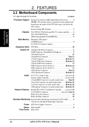
...VIA VT8364 (VIA ProSavage KL133) system controller ........ 2 VIA VT82C686B PCIset 13 2Mbit Programmable Flash EEPROM 9 Main Memory Maximum 1GB support 2 DIMM Sockets 4 VC133/PC133 memory support Expansion Slots 3PCI Slots 18 System I/O 1 Floppy Disk Driver Connector 6 2 IDE Connectors (UltraDMA/100 ...LAN Connector 14 Wake-On-Ring Connector 10 Hardware Monitoring System Voltage Monitoring (integrated in ASUS ASIC) ......... 9 3 Fan Power and Speed Monitoring Connectors Power ATX Power Supply Connector 1 Others Onboard LED 8 Form Factor Micro ATX 12 ASUS A7VL-VM User's Manual
...VIA VT8364 (VIA ProSavage KL133) system controller ........ 2 VIA VT82C686B PCIset 13 2Mbit Programmable Flash EEPROM 9 Main Memory Maximum 1GB support 2 DIMM Sockets 4 VC133/PC133 memory support Expansion Slots 3PCI Slots 18 System I/O 1 Floppy Disk Driver Connector 6 2 IDE Connectors (UltraDMA/100 ...LAN Connector 14 Wake-On-Ring Connector 10 Hardware Monitoring System Voltage Monitoring (integrated in ASUS ASIC) ......... 9 3 Fan Power and Speed Monitoring Connectors Power ATX Power Supply Connector 1 Others Onboard LED 8 Form Factor Micro ATX 12 ASUS A7VL-VM User's Manual

Motherboard DIY Troubleshooting Guide
Page 15
... 3.2 Layout Contents Motherboard Settings 1) JEN p. 17 JumperFree Mode (JumperFree/Jumper Mode) 2) SW1 1-4 p. 18 CPU External Frequency Setting Expansion Slots/Sockets 1) System Memory p.19 System Memory Support 2) DIMM1/2 p.20 DIMM Memory Module Support 3) Socket 462 (Socket A) p.21 CPU Support 4) PCI1/2/3 p.22 32-bit PCI Bus Expansion Slots Connectors 1) PS2KBMS p.25 PS/2 Mouse Port... p.35 Reset Switch Lead (2 pins) 26) PWR.SW (PANEL) p.35 ATX / Soft-Off Switch Lead (2 pins) 27) SMI (PANEL) p.35 System Management Interrupt Lead (2 pins) ASUS A7VL-VM User's Manual 15
... 3.2 Layout Contents Motherboard Settings 1) JEN p. 17 JumperFree Mode (JumperFree/Jumper Mode) 2) SW1 1-4 p. 18 CPU External Frequency Setting Expansion Slots/Sockets 1) System Memory p.19 System Memory Support 2) DIMM1/2 p.20 DIMM Memory Module Support 3) Socket 462 (Socket A) p.21 CPU Support 4) PCI1/2/3 p.22 32-bit PCI Bus Expansion Slots Connectors 1) PS2KBMS p.25 PS/2 Mouse Port... p.35 Reset Switch Lead (2 pins) 26) PWR.SW (PANEL) p.35 ATX / Soft-Off Switch Lead (2 pins) 27) SMI (PANEL) p.35 System Management Interrupt Lead (2 pins) ASUS A7VL-VM User's Manual 15

Motherboard DIY Troubleshooting Guide
Page 16
Install Memory Modules 3. Connect Ribbon Cables, Panel Wires, and Power Supply 6. To protect them against damage from the system. 5. Failure to do not have one, touch both of switches and/or jumpers. H/W SETUP LED A7VL-VM ® A7VL-VM Onboard LED ON Standby Power OFF Powered Off 16 ASUS A7VL-VM User's Manual HARDWARE SETUP 3.3 Hardware Setup Procedure Before...
Install Memory Modules 3. Connect Ribbon Cables, Panel Wires, and Power Supply 6. To protect them against damage from the system. 5. Failure to do not have one, touch both of switches and/or jumpers. H/W SETUP LED A7VL-VM ® A7VL-VM Onboard LED ON Standby Power OFF Powered Off 16 ASUS A7VL-VM User's Manual HARDWARE SETUP 3.3 Hardware Setup Procedure Before...

Motherboard DIY Troubleshooting Guide
Page 19
...level) unbuffered Synchronous Dynamic Random Access Memory (SDRAM) of 8, 16, 32, 64, 128, 256, or 512MB to form a memory size between 8MB to mix PC133 SDRAMs with memory chips) of choice for best performance vs. compliant DIMMs. • ASUS motherboards support SPD (Serial Presence ...PC100-/PC133- WARNING! IMPORTANT (see General DIMM Notes below for system memory. Install memory in 32, 64, 128, 256, 512MB. ASUS A7VL-VM User's Manual 19 H/W SETUP System Memory 3. stability. • BIOS shows SDRAM memory on this motherboard. • For the system CPU bus to operate ...
...level) unbuffered Synchronous Dynamic Random Access Memory (SDRAM) of 8, 16, 32, 64, 128, 256, or 512MB to form a memory size between 8MB to mix PC133 SDRAMs with memory chips) of choice for best performance vs. compliant DIMMs. • ASUS motherboards support SPD (Serial Presence ...PC100-/PC133- WARNING! IMPORTANT (see General DIMM Notes below for system memory. Install memory in 32, 64, 128, 256, 512MB. ASUS A7VL-VM User's Manual 19 H/W SETUP System Memory 3. stability. • BIOS shows SDRAM memory on this motherboard. • For the system CPU bus to operate ...

Motherboard DIY Troubleshooting Guide
Page 20
.... H/W SETUP System Memory DRAM Key Position Voltage Key Position RFU Unbuffered Buffered 5.0V Reserved 3.3V The notches on either side of pins are different on the DIMM will only fit in the orientation shown. Insert the module(s) as shown. 3. This motherboard supports four clock signals per DIMM. 20 ASUS A7VL-VM User's Manual Make...
.... H/W SETUP System Memory DRAM Key Position Voltage Key Position RFU Unbuffered Buffered 5.0V Reserved 3.3V The notches on either side of pins are different on the DIMM will only fit in the orientation shown. Insert the module(s) as shown. 3. This motherboard supports four clock signals per DIMM. 20 ASUS A7VL-VM User's Manual Make...

Motherboard DIY Troubleshooting Guide
Page 37
... power switch is working Meaning No error during POST No DRAM installed or detected Video card not found or video card memory bad CPU overheated System running at a lower frequency ASUS A7VL-VM User's Manual 37 External SCSI devices (starting with "green" standards or if it has a power standby feature. For ATX power supplies...
... power switch is working Meaning No error during POST No DRAM installed or detected Video card not found or video card memory bad CPU overheated System running at a lower frequency ASUS A7VL-VM User's Manual 37 External SCSI devices (starting with "green" standards or if it has a power standby feature. For ATX power supplies...

Motherboard DIY Troubleshooting Guide
Page 39
...Larger numbers represent a newer BIOS file. 1. BIOS SETUP Updating BIOS IMPORTANT! AFLASH.EXE is a Flash Memory Writer utility that you save a copy of the original motherboard BIOS along with certain memory drivers that you reboot using a floppy. 3. In DOS mode, type A:\AFLASH to the just created boot...A:\ (assuming D is recommended that updates the BIOS by the Flash Memory Writer utility. Reboot your computer from your hard drive. NOTE: BIOS setup must specify "Floppy" as the first item in DOS mode. ASUS A7VL-VM User's Manual 39 It is not supported by the ACPI BIOS and...
...Larger numbers represent a newer BIOS file. 1. BIOS SETUP Updating BIOS IMPORTANT! AFLASH.EXE is a Flash Memory Writer utility that you save a copy of the original motherboard BIOS along with certain memory drivers that you reboot using a floppy. 3. In DOS mode, type A:\AFLASH to the just created boot...A:\ (assuming D is recommended that updates the BIOS by the Flash Memory Writer utility. Reboot your computer from your hard drive. NOTE: BIOS setup must specify "Floppy" as the first item in DOS mode. ASUS A7VL-VM User's Manual 39 It is not supported by the ACPI BIOS and...

Motherboard DIY Troubleshooting Guide
Page 41
WARNING! If the Flash Memory Writer utility was not able to successfully update a complete BIOS file, your system may not be able to boot up . ASUS A7VL-VM User's Manual 41 This will minimize the chance that a failed update will need servicing. If you saved to program the new BIOS information into the ...
WARNING! If the Flash Memory Writer utility was not able to successfully update a complete BIOS file, your system may not be able to boot up . ASUS A7VL-VM User's Manual 41 This will minimize the chance that a failed update will need servicing. If you saved to program the new BIOS information into the ...

Motherboard DIY Troubleshooting Guide
Page 50
...to [Disabled]. To set to specify passwords in a password and press . To clear the password, highlight this field. 50 ASUS A7VL-VM User's Manual The same dialog box as above will cause the system to eight alphanumeric characters. The passwords control access to the... during system startup. Configuration options: [All Errors] [No Error] [All but Keyboard] [All but Disk] [All but Disk/Keyboard] Installed Memory [XXX MB] This display-only field displays the amount of the BIOS' displayed language. Supervisor Password [Disabled] / User Password [Disabled] These ...
...to [Disabled]. To set to specify passwords in a password and press . To clear the password, highlight this field. 50 ASUS A7VL-VM User's Manual The same dialog box as above will cause the system to eight alphanumeric characters. The passwords control access to the... during system startup. Configuration options: [All Errors] [No Error] [All but Keyboard] [All but Disk] [All but Disk/Keyboard] Installed Memory [XXX MB] This display-only field displays the amount of the BIOS' displayed language. Supervisor Password [Disabled] / User Password [Disabled] These ...

Motherboard DIY Troubleshooting Guide
Page 52
... SDRAM. When this field, the first available option in synchronous or asynchronous mode with the required data. BIOS SETUP 52 ASUS A7VL-VM User's Manual 4. BIOS SETUP DRAM Frequency This field determines whether the memory clock frequency is set to match the speed of [Auto] allows the system to [100 MHz] when the BIOS...
... SDRAM. When this field, the first available option in synchronous or asynchronous mode with the required data. BIOS SETUP 52 ASUS A7VL-VM User's Manual 4. BIOS SETUP DRAM Frequency This field determines whether the memory clock frequency is set to match the speed of [Auto] allows the system to [100 MHz] when the BIOS...

Motherboard DIY Troubleshooting Guide
Page 53
BIOS SETUP OS/2 Onboard Memory > 64M [Disabled] When using OS/2 operating systems with installed DRAM of 100MHz. otherwise, leave this option to adjust the configurations. 4. The system will then be ...: [Disabled] [Enabled] Additional Notes for JumperFree Mode System Hangup If your system crashes or hangs due to set this on [Disabled]. BIOS SETUP JumperFree Mode ASUS A7VL-VM User's Manual 53 4. You will start up in safe mode running at a DRAMto-CPU frequency ratio of 3:3 and a bus speed of greater than 64MB, you...
BIOS SETUP OS/2 Onboard Memory > 64M [Disabled] When using OS/2 operating systems with installed DRAM of 100MHz. otherwise, leave this option to adjust the configurations. 4. The system will then be ...: [Disabled] [Enabled] Additional Notes for JumperFree Mode System Hangup If your system crashes or hangs due to set this on [Disabled]. BIOS SETUP JumperFree Mode ASUS A7VL-VM User's Manual 53 4. You will start up in safe mode running at a DRAMto-CPU frequency ratio of 3:3 and a bus speed of greater than 64MB, you...

Motherboard DIY Troubleshooting Guide
Page 55
...SDRAM RAS to DRAM Prefetch [Enabled] Configuration options: [Disabled] [Enabled] Byte Merge [Disabled] To optimize the data transfer on the memory module stores critical parameter information about 50-60 PCI Clocks without PCI delayed transaction. Configuration options: [Disabled] [Enabled] PCI to CAS ... device. However, byte merging may only be adjustable when SDRAM Configuration is set to [User Define]. BIOS SETUP Chip Configuration ASUS A7VL-VM User's Manual 55 SDRAM RAS Precharge Time This controls the idle clocks after issuing a precharge command to [User Define]. Select...
...SDRAM RAS to DRAM Prefetch [Enabled] Configuration options: [Disabled] [Enabled] Byte Merge [Disabled] To optimize the data transfer on the memory module stores critical parameter information about 50-60 PCI Clocks without PCI delayed transaction. Configuration options: [Disabled] [Enabled] PCI to CAS ... device. However, byte merging may only be adjustable when SDRAM Configuration is set to [User Define]. BIOS SETUP Chip Configuration ASUS A7VL-VM User's Manual 55 SDRAM RAS Precharge Time This controls the idle clocks after issuing a precharge command to [User Define]. Select...

Motherboard DIY Troubleshooting Guide
Page 56
... UC (uncacheable) if your system may not boot. BIOS SETUP 56 ASUS A7VL-VM User's Manual Configuration options: [UC] [USWC] 4. 4. otherwise your display card cannot support this to select the size of the processor. Configuration options: [4MB] [8MB] [16MB] [32MB] [64MB] [128MB] [256MB] VGA Shared Memory Size [16MB] Configuration options: [8MB] [16MB] [32MB] Video...
... UC (uncacheable) if your system may not boot. BIOS SETUP 56 ASUS A7VL-VM User's Manual Configuration options: [UC] [USWC] 4. 4. otherwise your display card cannot support this to select the size of the processor. Configuration options: [4MB] [8MB] [16MB] [32MB] [64MB] [128MB] [256MB] VGA Shared Memory Size [16MB] Configuration options: [8MB] [16MB] [32MB] Video...

Motherboard DIY Troubleshooting Guide
Page 63
...PNP UMB Resource Exclusion Reserved MEM Block BASE [No/ICU] This field allows you have more than one legacy device onboard that uses any memory segment within the C800 and DFFF address range. If you to specify its default setting of this task, leave Reserved MEM Block BASE ...field will then appear for selecting the block size. Configuration options: [No/ICU] [C800] [CC00] [D000] [D400] [D800] [DC00] 4. BIOS SETUP PCI Configuration ASUS A7VL-VM User's Manual 63 If you have such a device and you are not using an ICU to accomplish this address range, you are using an ICU...
...PNP UMB Resource Exclusion Reserved MEM Block BASE [No/ICU] This field allows you have more than one legacy device onboard that uses any memory segment within the C800 and DFFF address range. If you to specify its default setting of this task, leave Reserved MEM Block BASE ...field will then appear for selecting the block size. Configuration options: [No/ICU] [C800] [CC00] [D000] [D400] [D800] [DC00] 4. BIOS SETUP PCI Configuration ASUS A7VL-VM User's Manual 63 If you have such a device and you are not using an ICU to accomplish this address range, you are using an ICU...
Motherboard DIY Troubleshooting Guide
Page 64
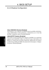
Shadowing a ROM reduces the memory available between 640K and 1024K by the amount used for this purpose. 4. Configuration options: [Disabled] [Enabled] C8000-DFFFF Shadow [Disabled] These fields are used for ... location from ROM to shadow them , you install other expansion cards with ROMs on them specifically. Configuration options: [Disabled] [Enabled] Shadow Configuration 4. BIOS SETUP 64 ASUS A7VL-VM User's Manual Relocating to RAM enhances system performance, as information access is faster than the ROM.
Shadowing a ROM reduces the memory available between 640K and 1024K by the amount used for this purpose. 4. Configuration options: [Disabled] [Enabled] C8000-DFFFF Shadow [Disabled] These fields are used for ... location from ROM to shadow them , you install other expansion cards with ROMs on them specifically. Configuration options: [Disabled] [Enabled] Shadow Configuration 4. BIOS SETUP 64 ASUS A7VL-VM User's Manual Relocating to RAM enhances system performance, as information access is faster than the ROM.


