
Motherboard DIY Troubleshooting Guide
Page 2
...product is authorized in the manual revision number. Copyright © 2001 ASUSTeK COMPUTER INC. Product Name: ASUS A7VL-VM Manual Revision: 1.04 E726 Release Date: March 2001 2 ASUS A7VL-VM User's Manual Manual updates are both printed on the following page. For previous or updated manuals, ...BIOS, drivers, or product release information, contact ASUS at http://www.asus.com.tw or through any means, except documentation...
...product is authorized in the manual revision number. Copyright © 2001 ASUSTeK COMPUTER INC. Product Name: ASUS A7VL-VM Manual Revision: 1.04 E726 Release Date: March 2001 2 ASUS A7VL-VM User's Manual Manual updates are both printed on the following page. For previous or updated manuals, ...BIOS, drivers, or product release information, contact ASUS at http://www.asus.com.tw or through any means, except documentation...
Motherboard DIY Troubleshooting Guide
Page 3
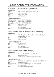
...) Notebook (Tel): +886-2-2890-7122 (English) Desktop/Server (Tel):+886-2-2890-7123 (English) Fax: +886-2-2893-7775 Email: tsd@asus.com.tw WWW: www.asus.com.tw FTP: ftp.asus.com.tw/pub/ASUS ASUS COMPUTER INTERNATIONAL (America) Marketing Address: 6737 Mowry Avenue, Mowry Business Center, Building 2 Newark, CA 94560, USA Fax: +1-510-608-4555... Fax: +49-2102-9599-11 Support (Email): www.asuscom.de/de/support (for online support) WWW: www.asuscom.de FTP: ftp.asuscom.de/pub/ASUSCOM ASUS A7VL-VM User's Manual 3
...) Notebook (Tel): +886-2-2890-7122 (English) Desktop/Server (Tel):+886-2-2890-7123 (English) Fax: +886-2-2893-7775 Email: tsd@asus.com.tw WWW: www.asus.com.tw FTP: ftp.asus.com.tw/pub/ASUS ASUS COMPUTER INTERNATIONAL (America) Marketing Address: 6737 Mowry Avenue, Mowry Business Center, Building 2 Newark, CA 94560, USA Fax: +1-510-608-4555... Fax: +49-2102-9599-11 Support (Email): www.asuscom.de/de/support (for online support) WWW: www.asuscom.de FTP: ftp.asuscom.de/pub/ASUSCOM ASUS A7VL-VM User's Manual 3

Motherboard DIY Troubleshooting Guide
Page 4
... 4.1.1 Upon First Use of the Computer System 39 4.1.2 Updating BIOS Procedures 40 4.2 BIOS Setup Program 42 4.2.1 BIOS Menu Bar 43 4.2.2 Legend Bar 43 4 ASUS A7VL-VM User's Manual FEATURES 8 2.1 The ASUS A7VL-VM 8 2.1.1 Specifications 8 2.1.2 Special Features 10 2.1.3 Optional Components 10 2.1.4 Performance Features 10 2.1.5 Intelligence 11 2.2 Motherboard Components 12 2.2.1 Component Locations 13 3. INTRODUCTION 7 1.1 How This Manual Is...
... 4.1.1 Upon First Use of the Computer System 39 4.1.2 Updating BIOS Procedures 40 4.2 BIOS Setup Program 42 4.2.1 BIOS Menu Bar 43 4.2.2 Legend Bar 43 4 ASUS A7VL-VM User's Manual FEATURES 8 2.1 The ASUS A7VL-VM 8 2.1.1 Specifications 8 2.1.2 Special Features 10 2.1.3 Optional Components 10 2.1.4 Performance Features 10 2.1.5 Intelligence 11 2.2 Motherboard Components 12 2.2.1 Component Locations 13 3. INTRODUCTION 7 1.1 How This Manual Is...
Motherboard DIY Troubleshooting Guide
Page 5
APPENDIX 87 7.1 PCI-L101 Fast Ethernet Card 87 7.2 Glossary 89 ASUS A7VL-VM User's Manual 5 SOFTWARE REFERENCE 77 6.1 ASUS PC Probe 77 6.2 CyberLink PowerPlayer SE 82 6.3 CyberLink PowerDVD 82 6.4 CyberLink VideoLive Mail 84 7. SOFTWARE SETUP 75 5.1 Install Operating System 75 5.2 Start Windows 75 5.3 A7VL-VM Series Support CD 76 6. CONTENTS 4.3 Main Menu 45 4.3.1 Primary & Secondary Master/Slave...
APPENDIX 87 7.1 PCI-L101 Fast Ethernet Card 87 7.2 Glossary 89 ASUS A7VL-VM User's Manual 5 SOFTWARE REFERENCE 77 6.1 ASUS PC Probe 77 6.2 CyberLink PowerPlayer SE 82 6.3 CyberLink PowerDVD 82 6.4 CyberLink VideoLive Mail 84 7. SOFTWARE SETUP 75 5.1 Install Operating System 75 5.2 Start Windows 75 5.3 A7VL-VM Series Support CD 76 6. CONTENTS 4.3 Main Menu 45 4.3.1 Primary & Secondary Master/Slave...
Motherboard DIY Troubleshooting Guide
Page 6
... the Federal Register, National Archives and Records Administration, U.S. Cet appareil numérique de la classe B est conforme à la norme NMB-003 du Canada. 6 ASUS A7VL-VM User's Manual Reprinted from digital apparatus set out in a residential installation. This equipment generates, uses and can be determined by turning the equipment off and...
... the Federal Register, National Archives and Records Administration, U.S. Cet appareil numérique de la classe B est conforme à la norme NMB-003 du Canada. 6 ASUS A7VL-VM User's Manual Reprinted from digital apparatus set out in a residential installation. This equipment generates, uses and can be determined by turning the equipment off and...

Motherboard DIY Troubleshooting Guide
Page 7
..." and two 3.5" floppy disk drives Optional Items ASUS CIDB chassis intrusion detection module ASUS IrDA-compliant infrared module ASUS PCI-L101 Wake-On-LAN 10/ 100 Ethernet Card (1) ASUS 2-port USB Connector Set (1) Bag of spare jumper caps (1) ASUS Support CD with drivers and utilities (1) This Motherboard User's Manual ASUS A7VL-VM User's Manual 7 SOFTWARE SETUP 6. FEATURES 3. SOFTWARE...
..." and two 3.5" floppy disk drives Optional Items ASUS CIDB chassis intrusion detection module ASUS IrDA-compliant infrared module ASUS PCI-L101 Wake-On-LAN 10/ 100 Ethernet Card (1) ASUS 2-port USB Connector Set (1) Bag of spare jumper caps (1) ASUS Support CD with drivers and utilities (1) This Motherboard User's Manual ASUS A7VL-VM User's Manual 7 SOFTWARE SETUP 6. FEATURES 3. SOFTWARE...

Motherboard DIY Troubleshooting Guide
Page 8
...activity through BIOS setup when JumperFree™ mode is optimized to 4 USB ports, two on two channels. FEATURES 2.1 The ASUS A7VL-VM The ASUS A7VL-VM motherboard is carefully designed for 4X, 2X, and 1X AGP modes; AC97 audio; up to deliver enhanced AMD Athlon™... system performance. • "Super South" South Bridge System PCIset: VIA VT82C686B PCI chipset with support for more peripheral connectivity options. 8 ASUS A7VL-VM User's Manual Appendix). • Wake-On-Ring Connector: Supports Wake-On-Ring activity through a PCI modem card that supports a WOR connector...
...activity through BIOS setup when JumperFree™ mode is optimized to 4 USB ports, two on two channels. FEATURES 2.1 The ASUS A7VL-VM The ASUS A7VL-VM motherboard is carefully designed for 4X, 2X, and 1X AGP modes; AC97 audio; up to deliver enhanced AMD Athlon™... system performance. • "Super South" South Bridge System PCIset: VIA VT82C686B PCI chipset with support for more peripheral connectivity options. 8 ASUS A7VL-VM User's Manual Appendix). • Wake-On-Ring Connector: Supports Wake-On-Ring activity through a PCI modem card that supports a WOR connector...

Motherboard DIY Troubleshooting Guide
Page 9
... easy way to examine and manage system status information, such as CPU and systerm voltages, temperatures, and fan status through the onboard hardware ASUS ASIC and the bundled ASUS PC Probe. • SMBus: Features the System Management Bus interface, which is used to physically transport commands and information between SMBus devices. •...; Concurrent PCI: Concurrent PCI allows multiple PCI transfers from PCI master busses to meet PC 99 compliancy, major connectors in this motherboard are color-coded. ASUS A7VL-VM User's Manual 9 FEA TURES Specifications 2. 2.
... easy way to examine and manage system status information, such as CPU and systerm voltages, temperatures, and fan status through the onboard hardware ASUS ASIC and the bundled ASUS PC Probe. • SMBus: Features the System Management Bus interface, which is used to physically transport commands and information between SMBus devices. •...; Concurrent PCI: Concurrent PCI allows multiple PCI transfers from PCI master busses to meet PC 99 compliancy, major connectors in this motherboard are color-coded. ASUS A7VL-VM User's Manual 9 FEA TURES Specifications 2. 2.

Motherboard DIY Troubleshooting Guide
Page 10
... master busses to the memory and processor. • High-Speed Data Transfer Interface: IDE transfers using UltraDMA/33 Bus Master IDE can be enabled.) 10 ASUS A7VL-VM User's Manual Color-coded connectors and descriptive icons make the setup of hard disk drives, expansion cards, and other devices virtually automatic. • New Compliancy...
... master busses to the memory and processor. • High-Speed Data Transfer Interface: IDE transfers using UltraDMA/33 Bus Master IDE can be enabled.) 10 ASUS A7VL-VM User's Manual Color-coded connectors and descriptive icons make the setup of hard disk drives, expansion cards, and other devices virtually automatic. • New Compliancy...

Motherboard DIY Troubleshooting Guide
Page 11
... to the industry standard SDRAM. All fans are more protection. Voltage specifications are set for RPM and failure. ASUS A7VL-VM User's Manual 11 FEA TURES Intelligence 2. When the power button is monitored by the ASUS ASIC to prevent system overheat and system damage. • Voltage Monitoring and Alert: System voltage levels are used... management. • Chassis Intrusion Detection: Supports chassis-intrusion monitoring through an internal or external modem. Suggestions will power off mode, depending on remotely through the ASUS ASIC.
... to the industry standard SDRAM. All fans are more protection. Voltage specifications are set for RPM and failure. ASUS A7VL-VM User's Manual 11 FEA TURES Intelligence 2. When the power button is monitored by the ASUS ASIC to prevent system overheat and system damage. • Voltage Monitoring and Alert: System voltage levels are used... management. • Chassis Intrusion Detection: Supports chassis-intrusion monitoring through an internal or external modem. Suggestions will power off mode, depending on remotely through the ASUS ASIC.
Motherboard DIY Troubleshooting Guide
Page 12
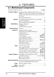
... ....... (optional) 19 1 LAN (RJ45) Connector optional) (top) 24 Wake-On-LAN Connector 14 Wake-On-Ring Connector 10 Hardware Monitoring System Voltage Monitoring (integrated in ASUS ASIC) ......... 9 3 Fan Power and Speed Monitoring Connectors Power ATX Power Supply Connector 1 Others Onboard LED 8 Form Factor Micro ATX 12 ASUS A7VL-VM User's Manual 2.
... ....... (optional) 19 1 LAN (RJ45) Connector optional) (top) 24 Wake-On-LAN Connector 14 Wake-On-Ring Connector 10 Hardware Monitoring System Voltage Monitoring (integrated in ASUS ASIC) ......... 9 3 Fan Power and Speed Monitoring Connectors Power ATX Power Supply Connector 1 Others Onboard LED 8 Form Factor Micro ATX 12 ASUS A7VL-VM User's Manual 2.

Motherboard DIY Troubleshooting Guide
Page 13
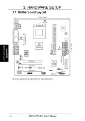
FEA TURES Motherboard Parts 2. FEATURES 2.2.1 Component Locations 1 2 3 25 24 23 4 5 6 78 22 21 20 19 18 17 16 15 - 14 13 12 11 10 9 ASUS A7VL-VM User's Manual 13 2.
FEA TURES Motherboard Parts 2. FEATURES 2.2.1 Component Locations 1 2 3 25 24 23 4 5 6 78 22 21 20 19 18 17 16 15 - 14 13 12 11 10 9 ASUS A7VL-VM User's Manual 13 2.
Motherboard DIY Troubleshooting Guide
Page 14
... 1 HPHONE PCI Slot 2 MODEM WOLCON Audio Chip PCI Slot 3 ® A7VL-VM COM2 SW1 PRIMARY IDE SECONDARY IDE Flash EEPROM (Programable BIOS) CHASSIS JEN 0 1 2 3 VIA VT82C686B Chipset IR SMB IDELED USB2 WOR HPANEL Grayed components are optional at the time of purchase. 24.5cm (9.6in) FLOPPY 3. H/W SETUP Motherboard Layout 14 ASUS A7VL-VM User's Manual 3.
... 1 HPHONE PCI Slot 2 MODEM WOLCON Audio Chip PCI Slot 3 ® A7VL-VM COM2 SW1 PRIMARY IDE SECONDARY IDE Flash EEPROM (Programable BIOS) CHASSIS JEN 0 1 2 3 VIA VT82C686B Chipset IR SMB IDELED USB2 WOR HPANEL Grayed components are optional at the time of purchase. 24.5cm (9.6in) FLOPPY 3. H/W SETUP Motherboard Layout 14 ASUS A7VL-VM User's Manual 3.

Motherboard DIY Troubleshooting Guide
Page 15
...) p.35 Reset Switch Lead (2 pins) 26) PWR.SW (PANEL) p.35 ATX / Soft-Off Switch Lead (2 pins) 27) SMI (PANEL) p.35 System Management Interrupt Lead (2 pins) ASUS A7VL-VM User's Manual 15 H/W SETUP Layout Contents 3.
...) p.35 Reset Switch Lead (2 pins) 26) PWR.SW (PANEL) p.35 ATX / Soft-Off Switch Lead (2 pins) 27) SMI (PANEL) p.35 System Management Interrupt Lead (2 pins) ASUS A7VL-VM User's Manual 15 H/W SETUP Layout Contents 3.

Motherboard DIY Troubleshooting Guide
Page 16
... a metal object, such as a reminder that you plug in suspend or soft-off before handling computer components. Install Expansion Cards 5. 3. Install Memory Modules 3. H/W SETUP LED A7VL-VM ® A7VL-VM Onboard LED ON Standby Power OFF Powered Off 16 ASUS A7VL-VM User's Manual
... a metal object, such as a reminder that you plug in suspend or soft-off before handling computer components. Install Expansion Cards 5. 3. Install Memory Modules 3. H/W SETUP LED A7VL-VM ® A7VL-VM Onboard LED ON Standby Power OFF Powered Off 16 ASUS A7VL-VM User's Manual

Motherboard DIY Troubleshooting Guide
Page 17
...to be set as shown: (ON: 1,2,4; H/W SETUP Motherboard Settings 3. 4ON3 2 1 1 2 3 O4N 3. OFF: 3) DSW (Default) ON 1234 A7VL-VM ® A7VL-VM JumperFree™ Mode Setting 100MHz JEN 12 Jumper Mode 2 3 JumperFree (Default) ASUS A7VL-VM User's Manual 17 Frequency Selection 3. The white block represents the switch's position. HARDWARE SETUP Motherboard Features Settings (DIP Switches... BIOS setup (see 4.4 Advanced Menu). The JumperFree™ mode allows processor settings to enable or disable the JumperFree™ mode. DSW A7VL-VM ® A7VL-VM DIP Switches ON OFF 1.
...to be set as shown: (ON: 1,2,4; H/W SETUP Motherboard Settings 3. 4ON3 2 1 1 2 3 O4N 3. OFF: 3) DSW (Default) ON 1234 A7VL-VM ® A7VL-VM JumperFree™ Mode Setting 100MHz JEN 12 Jumper Mode 2 3 JumperFree (Default) ASUS A7VL-VM User's Manual 17 Frequency Selection 3. The white block represents the switch's position. HARDWARE SETUP Motherboard Features Settings (DIP Switches... BIOS setup (see 4.4 Advanced Menu). The JumperFree™ mode allows processor settings to enable or disable the JumperFree™ mode. DSW A7VL-VM ® A7VL-VM DIP Switches ON OFF 1.

Motherboard DIY Troubleshooting Guide
Page 18
... 3. Otherwise, if JumperFree Mode is not recommended. ON ON 1234 CPU 100MHz 1234 103MHz ON ON 1234 CPU 105MHz 1234 110MHz A7VL-VM ® A7VL-VM CPU External Frequency Selection ON 1234 CPU 133MHz External Frequency Table CPU PCI (MHz) (MHz) 1 100.00 103.00 105.... page). 2. IMPORTANT: 1. This allows the selection of the processor. NOTE: For updated processor settings, visit the ASUS web site: www.asus.com (see ASUS CONTACT INFORMATION). 18 ASUS A7VL-VM User's Manual To use BIOS setup in place of these switches (set the CPU Frequency). It may result in ...
... 3. Otherwise, if JumperFree Mode is not recommended. ON ON 1234 CPU 100MHz 1234 103MHz ON ON 1234 CPU 105MHz 1234 110MHz A7VL-VM ® A7VL-VM CPU External Frequency Selection ON 1234 CPU 133MHz External Frequency Table CPU PCI (MHz) (MHz) 1 100.00 103.00 105.... page). 2. IMPORTANT: 1. This allows the selection of the processor. NOTE: For updated processor settings, visit the ASUS web site: www.asus.com (see ASUS CONTACT INFORMATION). 18 ASUS A7VL-VM User's Manual To use BIOS setup in place of these switches (set the CPU Frequency). It may result in ...

Motherboard DIY Troubleshooting Guide
Page 19
... 32, 64, 128, 256, 512MB. Be sure that have more ): • SDRAMs used must be possible. compliant DIMMs. • ASUS motherboards support SPD (Serial Presence Detect) DIMMs. This is recommended through SDRAM Configuration under "Chipset Features Setup". Registered DIMMs are not supported on ... bus to 1GB. One side (with VCM SDRAMs. • The motherboard only supports PC100 / PC133 DIMMs or VC SDRAMs for system memory. ASUS A7VL-VM User's Manual 19 double-sided come in any combination as follows: DIMM Location Socket 1 (Rows 0&1) Socket 2 (Rows 2&3) 168-pin DIMM ...
... 32, 64, 128, 256, 512MB. Be sure that have more ): • SDRAMs used must be possible. compliant DIMMs. • ASUS motherboards support SPD (Serial Presence Detect) DIMMs. This is recommended through SDRAM Configuration under "Chipset Features Setup". Registered DIMMs are not supported on ... bus to 1GB. One side (with VCM SDRAMs. • The motherboard only supports PC100 / PC133 DIMMs or VC SDRAMs for system memory. ASUS A7VL-VM User's Manual 19 double-sided come in any combination as follows: DIMM Location Socket 1 (Rows 0&1) Socket 2 (Rows 2&3) 168-pin DIMM ...

Motherboard DIY Troubleshooting Guide
Page 20
...inserted into the DIMM slot on either side of pins are different on the motherboard. This motherboard supports four clock signals per DIMM. 20 ASUS A7VL-VM User's Manual 3. HARDWARE SETUP 3.5.2 Memory Installation WARNING! DRAM SIMM modules have the same pin contacts on each side and therefore have different... figure below). 168-Pin DIMM Notch Key Definitions (3.3V) 3. SDRAM DIMMs have a higher pin density. 20 Pins 60 Pins 88 Pins A7VL-VM ® A7VL-VM 168-Pin DIMM Sockets The DIMMs must tell your power supply when adding or removing memory modules or other system components.
...inserted into the DIMM slot on either side of pins are different on the motherboard. This motherboard supports four clock signals per DIMM. 20 ASUS A7VL-VM User's Manual 3. HARDWARE SETUP 3.5.2 Memory Installation WARNING! DRAM SIMM modules have the same pin contacts on each side and therefore have different... figure below). 168-Pin DIMM Notch Key Definitions (3.3V) 3. SDRAM DIMMs have a higher pin density. 20 Pins 60 Pins 88 Pins A7VL-VM ® A7VL-VM 168-Pin DIMM Sockets The DIMMs must tell your power supply when adding or removing memory modules or other system components.
Motherboard DIY Troubleshooting Guide
Page 21
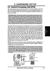
... or else boot-up may not be fully opened (90 to exert too much force, but press the CPU down the CPU. BLANK LEVER LOCK A7VL-VM ® A7VL-VM Socket A AMD™ Athlon NOTCH ASUS A7VL-VM User's Manual 21
... or else boot-up may not be fully opened (90 to exert too much force, but press the CPU down the CPU. BLANK LEVER LOCK A7VL-VM ® A7VL-VM Socket A AMD™ Athlon NOTCH ASUS A7VL-VM User's Manual 21


