Motherboard DIY Troubleshooting Guide
Page 5
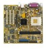
Motherboard-Layout PS/2KBMS T: Mouse B: Keyboard COM1 Socket 462 CPU_FAN DSW FLOPPY DDR DIMM1 (64 bit,184-pin module) DDR ...LAN_USB34 VIA KM400A Top:Line In Center:Line Out Below:Mic In Accelerated Graphics Port (AGP1) VIA VT6103 SPDIF AD1888 FP_AUDIO PCI1 A7V400-MX SE PCI2 CR2032 3V Lithium Cell CMOS Power VIA VT8237 PCI3 CLRTC USBPWR56 USBPWR78 SB_PWR AUX CD USB56 USB78 2Mbit ISA BIOS SATA2 ...SMI * Requires an ATX power supply. Prozessoren mit einer Taktfrequenz von kleiner 1 GHz dürfen nicht verwendet werden. Deutsch 1. ASUS A7V400-MX SE-Motherboard 5
Motherboard-Layout PS/2KBMS T: Mouse B: Keyboard COM1 Socket 462 CPU_FAN DSW FLOPPY DDR DIMM1 (64 bit,184-pin module) DDR ...LAN_USB34 VIA KM400A Top:Line In Center:Line Out Below:Mic In Accelerated Graphics Port (AGP1) VIA VT6103 SPDIF AD1888 FP_AUDIO PCI1 A7V400-MX SE PCI2 CR2032 3V Lithium Cell CMOS Power VIA VT8237 PCI3 CLRTC USBPWR56 USBPWR78 SB_PWR AUX CD USB56 USB78 2Mbit ISA BIOS SATA2 ...SMI * Requires an ATX power supply. Prozessoren mit einer Taktfrequenz von kleiner 1 GHz dürfen nicht verwendet werden. Deutsch 1. ASUS A7V400-MX SE-Motherboard 5
A7V400-MX SE user's manual for English version
Page 1
Motherboard A7V400-MX SE
Motherboard A7V400-MX SE
A7V400-MX SE user's manual for English version
Page 3
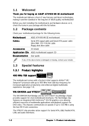
Contents Notices v Safety information vi About this guide vii A7V400-MX SE specifications summary viii Chapter 1: Product introduction 1.1 1.2 1.3 1.4 1.5 1.6 1.7 1.8 1.9 1.10 Welcome 1-2 Package contents 1-2 Special features 1-2 1.3.1 Product highlights 1-2 1.3.2 Innovative ASUS features 1-4 Before you proceed 1-5 Motherboard overview 1-6 1.5.1 Motherboard layout 1-6 1.5.2 Placement direction 1-7 1.5.3 Screw holes 1-7 Central Processing Unit (CPU 1-8 1.6.1 Overview 1-8 1.6.2 Installing the CPU 1-8 System memory 1-9 1.7.1 Overview 1-9 1.7.2 Memory configurations 1-9 ...
Contents Notices v Safety information vi About this guide vii A7V400-MX SE specifications summary viii Chapter 1: Product introduction 1.1 1.2 1.3 1.4 1.5 1.6 1.7 1.8 1.9 1.10 Welcome 1-2 Package contents 1-2 Special features 1-2 1.3.1 Product highlights 1-2 1.3.2 Innovative ASUS features 1-4 Before you proceed 1-5 Motherboard overview 1-6 1.5.1 Motherboard layout 1-6 1.5.2 Placement direction 1-7 1.5.3 Screw holes 1-7 Central Processing Unit (CPU 1-8 1.6.1 Overview 1-8 1.6.2 Installing the CPU 1-8 System memory 1-9 1.7.1 Overview 1-9 1.7.2 Memory configurations 1-9 ...
A7V400-MX SE user's manual for English version
Page 12
... at speeds of the above items is damaged or missing, contact your motherboard package for the following items. Motherboard ASUS A7V400-MX SE motherboard Cables Serial ATA signal cable and Serial ATA power cable Ultra DMA 133/100/66 cable Floppy disk drive cable Accessories I/O shield A p p l i c a t i o n C D s ASUS motherboard support CD D o c u m e n t a t i o n User guide If any of up to 533 MB...
... at speeds of the above items is damaged or missing, contact your motherboard package for the following items. Motherboard ASUS A7V400-MX SE motherboard Cables Serial ATA signal cable and Serial ATA power cable Ultra DMA 133/100/66 cable Floppy disk drive cable Accessories I/O shield A p p l i c a t i o n C D s ASUS motherboard support CD D o c u m e n t a t i o n User guide If any of up to 533 MB...
A7V400-MX SE user's manual for English version
Page 13
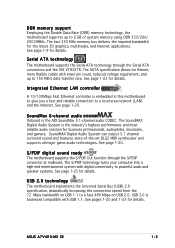
... the VIA VT8237R. USB 2.0 technology The motherboard implements the Universal Serial Bus (USB) 2.0 specification, dramatically increasing the connection speed from the 12 Mbps bandwidth on USB 1.1 to a local area network (LAN) and the Internet. ASUS A7V400-MX SE 1-3 SoundMAX Digital Audio System can output 5.1...SoundMax 6-channel audio Onboard is the industry's highest performance and most reliable audio solution for details. USB 2.0 is embedded in this motherboard to give you a fast and reliable connection to a fast 480 Mbps on USB 2.0. See page 1-22 for details. The ...
... the VIA VT8237R. USB 2.0 technology The motherboard implements the Universal Serial Bus (USB) 2.0 specification, dramatically increasing the connection speed from the 12 Mbps bandwidth on USB 1.1 to a local area network (LAN) and the Internet. ASUS A7V400-MX SE 1-3 SoundMAX Digital Audio System can output 5.1...SoundMax 6-channel audio Onboard is the industry's highest performance and most reliable audio solution for details. USB 2.0 is embedded in this motherboard to give you a fast and reliable connection to a fast 480 Mbps on USB 2.0. See page 1-22 for details. The ...

A7V400-MX SE user's manual for English version
Page 15
..., place it on them. • Whenever you install or remove any motherboard component. A7V400-MX SE A7V400-MX SE Onboard LED SB_PWR ON Standby Power OFF Powered Off ASUS A7V400-MX SE 1-5 The illustration below shows the location of the following precautions before you install motherboard components or change any motherboard settings. • Unplug the power cord from the wall socket before touching...
..., place it on them. • Whenever you install or remove any motherboard component. A7V400-MX SE A7V400-MX SE Onboard LED SB_PWR ON Standby Power OFF Powered Off ASUS A7V400-MX SE 1-5 The illustration below shows the location of the following precautions before you install motherboard components or change any motherboard settings. • Unplug the power cord from the wall socket before touching...
A7V400-MX SE user's manual for English version
Page 16
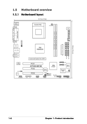
1.5 Motherboard overview 1.5.1 Motherboard layout 24.5cm (9.6in) PS/2KBMS T: Mouse B: Keyboard COM1 Socket 462 CPU_FAN DSW FLOPPY DDR DIMM1 (64 bit,184-pin module) DDR DIMM2 (64 bit,... USBPWR12 VGA1 USB12 LAN_USB34 VIA KM400A Top:Line In Center:Line Out Below:Mic In VIA VT6103 SPDIF AD1888 FP_AUDIO Accelerated Graphics Port (AGP1) PCI1 A7V400-MX SE PCI2 CR2032 3V Lithium Cell CMOS Power VIA VT8237 PCI3 CLRTC USBPWR56 USBPWR78 SB_PWR AUX CD USB56 USB78 2Mbit ISA BIOS SATA2 SATA1 Super I/O CHA_FAN1...
1.5 Motherboard overview 1.5.1 Motherboard layout 24.5cm (9.6in) PS/2KBMS T: Mouse B: Keyboard COM1 Socket 462 CPU_FAN DSW FLOPPY DDR DIMM1 (64 bit,184-pin module) DDR DIMM2 (64 bit,... USBPWR12 VGA1 USB12 LAN_USB34 VIA KM400A Top:Line In Center:Line Out Below:Mic In VIA VT6103 SPDIF AD1888 FP_AUDIO Accelerated Graphics Port (AGP1) PCI1 A7V400-MX SE PCI2 CR2032 3V Lithium Cell CMOS Power VIA VT8237 PCI3 CLRTC USBPWR56 USBPWR78 SB_PWR AUX CD USB56 USB78 2Mbit ISA BIOS SATA2 SATA1 Super I/O CHA_FAN1...
A7V400-MX SE user's manual for English version
Page 17
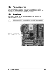
Do not overtighten the screws! Doing so can damage the motherboard. Place this side towards the rear of the chassis as indicated in the correct orientation. 1.5.2 Placement direction When installing the motherboard, make sure that you place it into the chassis in the image below. 1.5.3 Screw holes Place eight (8) screws into the holes indicated by circles to secure the motherboard to the rear part of the chassis ASUS A7V400-MX SE 1-7 The edge with external ports goes to the chassis.
Do not overtighten the screws! Doing so can damage the motherboard. Place this side towards the rear of the chassis as indicated in the correct orientation. 1.5.2 Placement direction When installing the motherboard, make sure that you place it into the chassis in the image below. 1.5.3 Screw holes Place eight (8) screws into the holes indicated by circles to secure the motherboard to the rear part of the chassis ASUS A7V400-MX SE 1-7 The edge with external ports goes to the chassis.
A7V400-MX SE user's manual for English version
Page 18
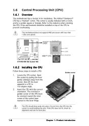
... angle. 2. This corner is usually indicated with less than 1 GHz core speed. A7V400-MX SE CPU NOTCH TO INNER CORNER AMD™ CPU LOCK LEVER CPU NOTCH A7V400-MX SE Socket 462 1.6.2 Installing the CPU Follow these steps to avoid bending the pins. This motherboard does not support AMD processors with a notch, and/or a golden square or...
... angle. 2. This corner is usually indicated with less than 1 GHz core speed. A7V400-MX SE CPU NOTCH TO INNER CORNER AMD™ CPU LOCK LEVER CPU NOTCH A7V400-MX SE Socket 462 1.6.2 Installing the CPU Follow these steps to avoid bending the pins. This motherboard does not support AMD processors with a notch, and/or a golden square or...
A7V400-MX SE user's manual for English version
Page 19
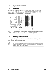
... DIMMs. Each DIMM socket is double-sided. DIMM1 DIMM2 ASUS A7V400-MX SE 1-9 See the next page for a list of up to the sockets. A7V400-MX SE A7V400-MX SE 184-pin DDR DIMM sockets * You can install a DDR400 DIMM(s) on the slot(s). 104 Pins 80 Pins 1.7 System memory 1.7.1 Overview The motherboard has two Double Data Rate (DDR) DIMM sockets that...
... DIMMs. Each DIMM socket is double-sided. DIMM1 DIMM2 ASUS A7V400-MX SE 1-9 See the next page for a list of up to the sockets. A7V400-MX SE A7V400-MX SE 184-pin DDR DIMM sockets * You can install a DDR400 DIMM(s) on the slot(s). 104 Pins 80 Pins 1.7 System memory 1.7.1 Overview The motherboard has two Double Data Rate (DDR) DIMM sockets that...
A7V400-MX SE user's manual for English version
Page 23
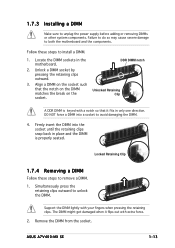
... into a socket to unplug the power supply before adding or removing DIMMs or other system components. Simultaneously press the retaining clips outward to both the motherboard and the components. ASUS A7V400-MX SE 1-13 Locate the DIMM sockets in the motherboard. 1.7.3 Installing a DIMM Make sure to avoid damaging the DIMM. 4.
... into a socket to unplug the power supply before adding or removing DIMMs or other system components. Simultaneously press the retaining clips outward to both the motherboard and the components. ASUS A7V400-MX SE 1-13 Locate the DIMM sockets in the motherboard. 1.7.3 Installing a DIMM Make sure to avoid damaging the DIMM. 4.
A7V400-MX SE user's manual for English version
Page 25
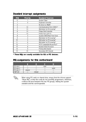
B - - - used - - - shared C used - - ASUS A7V400-MX SE 1-15 Standard interrupt assignments IRQ Priority 0 1 1 2 2 - 4 12 5 13 6 14 7 15 8 3 9 4 10 5 11 6 12 7 13 8 14 9 15 10 Standard Function System Timer Keyboard Controller...* IRQ holder for PCI steering* PS/2 Compatible Mouse Port* Numeric Data Processor Primary IDE Channel Secondary IDE Channel * These IRQs are usually available for this motherboard PCI slot 1 PCI slot 2 PCI slot 3 AGP slot A - - IRQ assignments for ISA or PCI devices. otherwise, conflicts will arise between the two PCI...
B - - - used - - - shared C used - - ASUS A7V400-MX SE 1-15 Standard interrupt assignments IRQ Priority 0 1 1 2 2 - 4 12 5 13 6 14 7 15 8 3 9 4 10 5 11 6 12 7 13 8 14 9 15 10 Standard Function System Timer Keyboard Controller...* IRQ holder for PCI steering* PS/2 Compatible Mouse Port* Numeric Data Processor Primary IDE Channel Secondary IDE Channel * These IRQs are usually available for this motherboard PCI slot 1 PCI slot 2 PCI slot 3 AGP slot A - - IRQ assignments for ISA or PCI devices. otherwise, conflicts will arise between the two PCI...
A7V400-MX SE user's manual for English version
Page 26
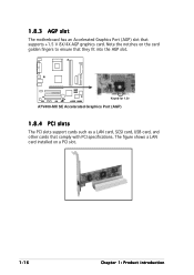
1.8.3 AGP slot The motherboard has an Accelerated Graphics Port (AGP) slot that comply with PCI specifications. Note the notches on a PCI slot. 1-16 Chapter 1: Product introduction The figure shows a LAN card installed on the card golden fingers to ensure that they fit into the AGP slot. A7V400-MX SE Keyed for 1.5v A7V400-MX SE Accelerated Graphics Port (AGP) 1.8.4 PCI slots The PCI slots support cards such as a LAN card, SCSI card, USB card, and other cards that supports +1.5 V 8X/4X AGP graphics card.
1.8.3 AGP slot The motherboard has an Accelerated Graphics Port (AGP) slot that comply with PCI specifications. Note the notches on a PCI slot. 1-16 Chapter 1: Product introduction The figure shows a LAN card installed on the card golden fingers to ensure that they fit into the AGP slot. A7V400-MX SE Keyed for 1.5v A7V400-MX SE Accelerated Graphics Port (AGP) 1.8.4 PCI slots The PCI slots support cards such as a LAN card, SCSI card, USB card, and other cards that supports +1.5 V 8X/4X AGP graphics card.
A7V400-MX SE user's manual for English version
Page 27
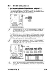
...motherboard to send the CPU. Frequencies other than the recommended CPU bus frequencies are using a locked CPU, setting the switches does not produce any effect. The white block represents the switch position. The bus clock multiplied by the frequency multiple equals the CPU's internal frequency (the advertised CPU speed). ASUS A7V400-MX SE... (or bus clock). CPU external frequency selection (DSW Switches 1-5) The motherboard frequency is 100 MHz. A7V400-MX SE ON OFF (Default) O1 2 3 4 5 N 100MHz 66.67MHz 33.33MHz A7V400-MX SE DIP switches The option to the recommended settings.
...motherboard to send the CPU. Frequencies other than the recommended CPU bus frequencies are using a locked CPU, setting the switches does not produce any effect. The white block represents the switch position. The bus clock multiplied by the frequency multiple equals the CPU's internal frequency (the advertised CPU speed). ASUS A7V400-MX SE... (or bus clock). CPU external frequency selection (DSW Switches 1-5) The motherboard frequency is 100 MHz. A7V400-MX SE ON OFF (Default) O1 2 3 4 5 N 100MHz 66.67MHz 33.33MHz A7V400-MX SE DIP switches The option to the recommended settings.

A7V400-MX SE user's manual for English version
Page 31
...Orient the red markings on the IDE ribbon cable to PIN 1. A7V400-MX SE PIN 1 A7V400-MX SE Floppy disk drive connector 2 . The Ultra DMA 133 signal cable has three connectors: a blue connector for the IDE connector on the motherboard, a black connector for an Ultra DMA 133/100/66 IDE slave...drives, you connect the IDE cable. • Use the 80-conductor IDE cable for Ultra DMA 133/100/66 IDE devices. A7V400-MX SE A7V400-MX SE IDE connectors ASUS A7V400-MX SE PRI_IDE SEC_IDE NOTE: Orient the red markings (usually zigzag) on the floppy ribbon cable to PIN 1. Floppy disk drive connector (...
...Orient the red markings on the IDE ribbon cable to PIN 1. A7V400-MX SE PIN 1 A7V400-MX SE Floppy disk drive connector 2 . The Ultra DMA 133 signal cable has three connectors: a blue connector for the IDE connector on the motherboard, a black connector for an Ultra DMA 133/100/66 IDE slave...drives, you connect the IDE cable. • Use the 80-conductor IDE cable for Ultra DMA 133/100/66 IDE devices. A7V400-MX SE A7V400-MX SE IDE connectors ASUS A7V400-MX SE PRI_IDE SEC_IDE NOTE: Orient the red markings (usually zigzag) on the floppy ribbon cable to PIN 1. Floppy disk drive connector (...
A7V400-MX SE user's manual for English version
Page 32
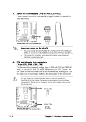
...inside the system may damage the motherboard components. CPU_FAN Rotation +12V GND A7V400-MX SE A7V400-MX SE Fan connectors CHA_FAN GND +12V Rotation 1-22 Chapter 1: Product introduction SATA2 GND RSATA_TXP2 RSATA_TXN2 GND RSATA_RXP2 RSATA_RXN2 GND A7V400-MX SE SATA1 GND RSATA_TXP1 RSATA_TXN1 GND RSATA_RXP1 RSATA_RXN1 GND A7V400-MX SE SATA connector Important notes on the...hard disk drives. Do not forget to connect the fan cables to the fan connectors on the motherboard, making sure that the black wire of each cable matches the ground pin of 1 A~2.22 A (26.64 W max.) at +12V...
...inside the system may damage the motherboard components. CPU_FAN Rotation +12V GND A7V400-MX SE A7V400-MX SE Fan connectors CHA_FAN GND +12V Rotation 1-22 Chapter 1: Product introduction SATA2 GND RSATA_TXP2 RSATA_TXN2 GND RSATA_RXP2 RSATA_RXN2 GND A7V400-MX SE SATA1 GND RSATA_TXP1 RSATA_TXN1 GND RSATA_RXP1 RSATA_RXN1 GND A7V400-MX SE SATA connector Important notes on the...hard disk drives. Do not forget to connect the fan cables to the fan connectors on the motherboard, making sure that the black wire of each cable matches the ground pin of 1 A~2.22 A (26.64 W max.) at +12V...
A7V400-MX SE user's manual for English version
Page 33
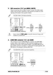
...to a slot opening at the back of the system chassis. Doing so will damage the motherboard! 6 . USB+5V USB_P8USB_P8+ GND NC USB+5V USB_P6USB_P6+ GND NC USB+5V USB_P7USB_P7+ GND USB+5V USB_P5USB_P5+ GND A7V400-MX SE USB56 1 A7V400-MX SE USB connectors USB78 1 Never connect a 1 3 9 4 c a b l e to... for a GAME/MIDI port. The USB module is purchased separately. +5V J1B2 J1CY GND GND J1CX J1B1 +5V A7V400-MX SE GAME A7V400-MX SE Game connector ASUS A7V400-MX SE MIDI_IN J2B2 J2CY MIDI_OUT J2CX J2B1 +5V 1-23 The GAME/MIDI module is purchased separately. 5 . Connect the GAME...
...to a slot opening at the back of the system chassis. Doing so will damage the motherboard! 6 . USB+5V USB_P8USB_P8+ GND NC USB+5V USB_P6USB_P6+ GND NC USB+5V USB_P7USB_P7+ GND USB+5V USB_P5USB_P5+ GND A7V400-MX SE USB56 1 A7V400-MX SE USB connectors USB78 1 Never connect a 1 3 9 4 c a b l e to... for a GAME/MIDI port. The USB module is purchased separately. +5V J1B2 J1CY GND GND J1CX J1B1 +5V A7V400-MX SE GAME A7V400-MX SE Game connector ASUS A7V400-MX SE MIDI_IN J2B2 J2CY MIDI_OUT J2CX J2B1 +5V 1-23 The GAME/MIDI module is purchased separately. 5 . Connect the GAME...
A7V400-MX SE user's manual for English version
Page 40
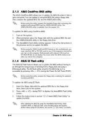
... updated BIOS file to the floppy disk drive, then turn on the system. 2. Motherboards with onboard VGA (such as A7V400-MX SE) do not display the screen when the BIOS crashes even after you reboot the computer. 2.1.4 ASUS EZ Flash utility The ASUS EZ Flash feature allows you turn on the computer. To update the BIOS...
... updated BIOS file to the floppy disk drive, then turn on the system. 2. Motherboards with onboard VGA (such as A7V400-MX SE) do not display the screen when the BIOS crashes even after you reboot the computer. 2.1.4 ASUS EZ Flash utility The ASUS EZ Flash feature allows you turn on the computer. To update the BIOS...
A7V400-MX SE user's manual for English version
Page 41
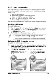
... you to manage, save, and update the motherboard BIOS in Windows® environment. Launch the ASUS Update utility from the nearest you to : ... BIOS directly from the Internet, and • View the BIOS version information. N e x t. ASUS A7V400-MX SE 2-5 The ASUS Update utility allows you update the BIOS using this utility. See page 3-3 for the U t i l i t i e s screen menu. 3. 2.1.5 ASUS Update utility The ASUS Update is a utility that comes with the motherboard package. Select U p d a t e B I n t e r n e t option from the Windows® desktop by clicking S t a r t > P r ...
... you to manage, save, and update the motherboard BIOS in Windows® environment. Launch the ASUS Update utility from the nearest you to : ... BIOS directly from the Internet, and • View the BIOS version information. N e x t. ASUS A7V400-MX SE 2-5 The ASUS Update utility allows you update the BIOS using this utility. See page 3-3 for the U t i l i t i e s screen menu. 3. 2.1.5 ASUS Update utility The ASUS Update is a utility that comes with the motherboard package. Select U p d a t e B I n t e r n e t option from the Windows® desktop by clicking S t a r t > P r ...
A7V400-MX SE user's manual for English version
Page 43
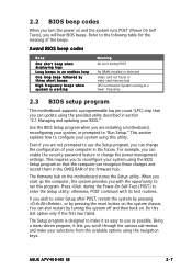
... for the meaning of the firmware hub. Refer to use as possible. System running at a lower frequency 2.3 BIOS setup program This motherboard supports a programmable low pin count (LPC) chip that the computer can recognize these changes and record them in the future. Use the...short beeps High frequency beeps when system is designed to configure your system using this last option only if the first two failed. ASUS A7V400-MX SE 2-7 This section explains how to make your selections from the available options using the provided utility described in section "2.1 Managing and...
... for the meaning of the firmware hub. Refer to use as possible. System running at a lower frequency 2.3 BIOS setup program This motherboard supports a programmable low pin count (LPC) chip that the computer can recognize these changes and record them in the future. Use the...short beeps High frequency beeps when system is designed to configure your system using this last option only if the first two failed. ASUS A7V400-MX SE 2-7 This section explains how to make your selections from the available options using the provided utility described in section "2.1 Managing and...


