
A7S-VM User Manual
Page 1
® A7S-VM SiS730S Ultra-AGP Socket A Motherboard USER'S MANUAL
® A7S-VM SiS730S Ultra-AGP Socket A Motherboard USER'S MANUAL

A7S-VM User Manual
Page 8
.../100 Support: Comes with an onboard PCI Bus Master IDE controller with Front Side Bus (FSB) frequency of the Socket A-based processor. 2. FEATURES 2.1 ASUS A7S-VM Motherboard Powered by AMD Athlon / AMD Duron processors, the ASUS A7S-VM motherboard bundles advanced technology to 1.2GHz with two connectors that complements the powers of 100MHz. • North/South Bridge...
.../100 Support: Comes with an onboard PCI Bus Master IDE controller with Front Side Bus (FSB) frequency of the Socket A-based processor. 2. FEATURES 2.1 ASUS A7S-VM Motherboard Powered by AMD Athlon / AMD Duron processors, the ASUS A7S-VM motherboard bundles advanced technology to 1.2GHz with two connectors that complements the powers of 100MHz. • North/South Bridge...
A7S-VM User Manual
Page 11
... in 4.5 Power Menu). With this benefit onhand, users can be monitored for RPM and failure. ASUS A7S-VM User's Manual 11 A chassis intrusion event is monitored by the ASUS ASIC through the thermal sensor of Socket A to prevent system overheat and system damage. • Voltage Monitoring and Alert: System voltage levels... 4 seconds, the system enters the soft-off mode regardless of two states: sleep mode or soft-off the computer remotely through the ASUS ASIC. All fans are more protection. When you to turn off mode, depending on battery power for more critical for more than 4...
... in 4.5 Power Menu). With this benefit onhand, users can be monitored for RPM and failure. ASUS A7S-VM User's Manual 11 A chassis intrusion event is monitored by the ASUS ASIC through the thermal sensor of Socket A to prevent system overheat and system damage. • Voltage Monitoring and Alert: System voltage levels... 4 seconds, the system enters the soft-off mode regardless of two states: sleep mode or soft-off the computer remotely through the ASUS ASIC. All fans are more protection. When you to turn off mode, depending on battery power for more critical for more than 4...
A7S-VM User Manual
Page 12
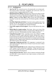
...System Controller 2 iTE IT8705F Super I/O Controller 8 2Mbit Programmable Flash EEPROM 10 Main Memory 2 DIMM Sockets for locations. FEATURES 2.2 Motherboard Components See opposite page for up to 1GB Memory Support 4 PC133 SDRAM... Connectors (Port 4 & Port 5 13 PS/2 Mouse Connector Top) 23 PS/2 Keyboard Connector Bottom) 23 Hardware Monitoring ASUS ASIC 15 3 Fan Power Connectors Network Features (on LAN models only) RealTek RTL8100 Fast Ethernet Controller 19 LAN Connector (RJ... Connector 1 Form Factor Micro ATX 12 ASUS A7S-VM User's Manual FEATURES M/B Components 2.
...System Controller 2 iTE IT8705F Super I/O Controller 8 2Mbit Programmable Flash EEPROM 10 Main Memory 2 DIMM Sockets for locations. FEATURES 2.2 Motherboard Components See opposite page for up to 1GB Memory Support 4 PC133 SDRAM... Connectors (Port 4 & Port 5 13 PS/2 Mouse Connector Top) 23 PS/2 Keyboard Connector Bottom) 23 Hardware Monitoring ASUS ASIC 15 3 Fan Power Connectors Network Features (on LAN models only) RealTek RTL8100 Fast Ethernet Controller 19 LAN Connector (RJ... Connector 1 Form Factor Micro ATX 12 ASUS A7S-VM User's Manual FEATURES M/B Components 2.
A7S-VM User Manual
Page 14
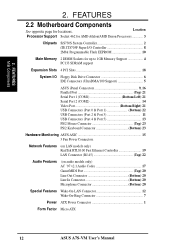
...) Socket A CPU_FAN CR2032 3V Lithium Cell CMOS Power CLR_CMOS ATX Power Connector PARALLEL PORT GAME_AUDIO VGA Line Out Line In Mic In Realtek TV-LCD Fast Enternet SiS730S Chipset PCI Slot 1 PWR_FAN CHASIS_FAN 01 23 1 1 PWR_TMP PCI Slot 2 CD Audio Codec VIDEO AUX PCI Slot 3 PCI Slot 4 MODEM A7S-VM AAPANEL USBP2 ASUS ASIC...
...) Socket A CPU_FAN CR2032 3V Lithium Cell CMOS Power CLR_CMOS ATX Power Connector PARALLEL PORT GAME_AUDIO VGA Line Out Line In Mic In Realtek TV-LCD Fast Enternet SiS730S Chipset PCI Slot 1 PWR_FAN CHASIS_FAN 01 23 1 1 PWR_TMP PCI Slot 2 CD Audio Codec VIDEO AUX PCI Slot 3 PCI Slot 4 MODEM A7S-VM AAPANEL USBP2 ASUS ASIC...

A7S-VM User Manual
Page 15
H/W SETUP Layout Contents Motherboard Settings 1) USB_UP 2) KB_UP 3) CLR_CMOS Expansion Slots/Sockets 1) DIMM 1/2 2) Socket A 3) PCI 1/2/3/4 External Connectors 1) PS2KBMS 2) PS2KBMS 3) RJ-45 4) USB 5) PRINTER 6) COM1 7) VGA 8) GAME_AUDIO (Top) 9) GAME_AUDIO (Bottom) Internal Connectors 1) IDELED 2) FLOPPY 3) PRIMARY IDE SECONDARY IDE 4) WOL_CON 5) WOR ...(4-pin) p. 38 System Message LED Lead (2-pin) p. 38 System Management Interrupt Lead (2-pin) p. 38 ATX / Soft-Off Switch Lead (2-pin) p. 38 Reset Switch Lead (2-pin) ASUS A7S-VM User's Manual 15 3. HARDWARE SETUP 3.2 Layout Contents 3.
H/W SETUP Layout Contents Motherboard Settings 1) USB_UP 2) KB_UP 3) CLR_CMOS Expansion Slots/Sockets 1) DIMM 1/2 2) Socket A 3) PCI 1/2/3/4 External Connectors 1) PS2KBMS 2) PS2KBMS 3) RJ-45 4) USB 5) PRINTER 6) COM1 7) VGA 8) GAME_AUDIO (Top) 9) GAME_AUDIO (Bottom) Internal Connectors 1) IDELED 2) FLOPPY 3) PRIMARY IDE SECONDARY IDE 4) WOL_CON 5) WOR ...(4-pin) p. 38 System Message LED Lead (2-pin) p. 38 System Management Interrupt Lead (2-pin) p. 38 ATX / Soft-Off Switch Lead (2-pin) p. 38 Reset Switch Lead (2-pin) ASUS A7S-VM User's Manual 15 3. HARDWARE SETUP 3.2 Layout Contents 3.

A7S-VM User Manual
Page 19
...have more than EDO (Extended Data Output) chips. • BIOS shows SDRAM memory on the motherboard. 3. H/W SETUP System Memory ASUS A7S-VM User's Manual 19 Two DIMM sockets are available for 3.3Volt (power level) unbuffered Synchronous Dynamic Random Access Memory (SDRAM) of 16, 32, 64, 128, 256..., or 512MB densities for best performance vs. compliant DIMMs. • ASUS motherboards support Serial Presence Detect (SPD) DIMMs. This is...
...have more than EDO (Extended Data Output) chips. • BIOS shows SDRAM memory on the motherboard. 3. H/W SETUP System Memory ASUS A7S-VM User's Manual 19 Two DIMM sockets are available for 3.3Volt (power level) unbuffered Synchronous Dynamic Random Access Memory (SDRAM) of 16, 32, 64, 128, 256..., or 512MB densities for best performance vs. compliant DIMMs. • ASUS motherboards support Serial Presence Detect (SPD) DIMMs. This is...

A7S-VM User Manual
Page 20
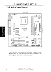
Failure to do so may cause severe damage to prevent the wrong type from being inserted into the DIMM sockets as shown. H/W SETUP System Memory The notches on the DIMM shifts between left, center, or right to identify the type and also to ...see 3.3 Hardware Setup Procedure for more information). This motherboard supports four clock signals per DIMM. 20 ASUS A7S-VM User's Manual SDRAM DIMMs have a higher pin density than DRAM SIMMs. 20 Pins 60 Pins 88 Pins A7S-VM A7S-VM 168-Pin DIMM Sockets Lock The DIMMs must tell your retailer the correct DIMM type before purchasing. 3.
Failure to do so may cause severe damage to prevent the wrong type from being inserted into the DIMM sockets as shown. H/W SETUP System Memory The notches on the DIMM shifts between left, center, or right to identify the type and also to ...see 3.3 Hardware Setup Procedure for more information). This motherboard supports four clock signals per DIMM. 20 ASUS A7S-VM User's Manual SDRAM DIMMs have a higher pin density than DRAM SIMMs. 20 Pins 60 Pins 88 Pins A7S-VM A7S-VM 168-Pin DIMM Sockets Lock The DIMMs must tell your retailer the correct DIMM type before purchasing. 3.
A7S-VM User Manual
Page 21
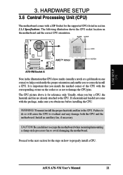
...the CPU. Install an auxillary fan, if necessary. Proceed to properly install a CPU. BLANK LEVER LOCK AMD™ Athlon NOTCH A7S-VM A7S-VM Socket A Note in section 2.1.1 Specifications. It is for the supported CPUs listed in the illustration that you match the marked corner of...already attached to avoid damaging the motherboard. CAUTION! ASUS A7S-VM User's Manual 21 H/W SETUP CPU 3. Usually, when you to damage the CPU pins. WARNING! HARDWARE SETUP 3.6 Central Processing Unit (CPU) The motherboard comes with a ZIF Socket for reference only. Be careful not to scrape...
...the CPU. Install an auxillary fan, if necessary. Proceed to properly install a CPU. BLANK LEVER LOCK AMD™ Athlon NOTCH A7S-VM A7S-VM Socket A Note in section 2.1.1 Specifications. It is for the supported CPUs listed in the illustration that you match the marked corner of...already attached to avoid damaging the motherboard. CAUTION! ASUS A7S-VM User's Manual 21 H/W SETUP CPU 3. Usually, when you to damage the CPU pins. WARNING! HARDWARE SETUP 3.6 Central Processing Unit (CPU) The motherboard comes with a ZIF Socket for reference only. Be careful not to scrape...

A7S-VM User Manual
Page 22
... or check for the processor to avoid start-up to the socket. 4. CAUTION! Attach the heatsink and fan to prevent bending the pins and damaging the CPU. Socket A processors requires a socket-mounted thermal resistor. 3. H/W SETUP CPU Installation 22 ASUS A7S-VM User's Manual Unlock the socket by the vendor. If the CPU does not fit completely, check...
... or check for the processor to avoid start-up to the socket. 4. CAUTION! Attach the heatsink and fan to prevent bending the pins and damaging the CPU. Socket A processors requires a socket-mounted thermal resistor. 3. H/W SETUP CPU Installation 22 ASUS A7S-VM User's Manual Unlock the socket by the vendor. If the CPU does not fit completely, check...

A7S-VM User Manual
Page 84
...DRAM). Normally, the flash ROM is responsible for system BIOS which all other symbol. APPENDIX Boot Boot means to 33MB/Sec transfer. 84 ASUS A7S-VM User's Manual will reboot your system (or computer), it into system memory. Bus master IDE transfers data to use a different IRQ ... interface between you to be a resident program and can be connected to peripheral devices. DRAM (Dynamic Random Access Memory) There are socket 370 (for Pentium III FC-PGA and CeleronPPGA), socket 7 (for Pentium, AMD, Cyrix, IBM), slot 1 (for Pentium II and III), slot 2 (for Xeon), and slot ...
...DRAM). Normally, the flash ROM is responsible for system BIOS which all other symbol. APPENDIX Boot Boot means to 33MB/Sec transfer. 84 ASUS A7S-VM User's Manual will reboot your system (or computer), it into system memory. Bus master IDE transfers data to use a different IRQ ... interface between you to be a resident program and can be connected to peripheral devices. DRAM (Dynamic Random Access Memory) There are socket 370 (for Pentium III FC-PGA and CeleronPPGA), socket 7 (for Pentium, AMD, Cyrix, IBM), slot 1 (for Pentium II and III), slot 2 (for Xeon), and slot ...

A7S-VM User Manual
Page 87
...Modules 19 DIMM Sockets 20 Types of 19 Voltage 20 E Expansion Cards Assigning IRQs 24 Installing 23 Expansion Slots 9 F Floppy 3 Mode 48 Floppy Disk Drive Connector 28, 35, 36 H Hard Disk Drives (HDDs) CHS Capacity 51 Cylinders 50 Heads 51 LBA Capacity 51 Primary/Secondary Master 49 ASUS A7S-VM User's Manual... 87 INDEX A AGP. See Accelerated Graphics Port ASUS PC Probe 77 Starting 77 Task Bar Icon 81 Using 77, 78 ATAPI CD-ROM 70 ATX Power Supply Connector 34...
...Modules 19 DIMM Sockets 20 Types of 19 Voltage 20 E Expansion Cards Assigning IRQs 24 Installing 23 Expansion Slots 9 F Floppy 3 Mode 48 Floppy Disk Drive Connector 28, 35, 36 H Hard Disk Drives (HDDs) CHS Capacity 51 Cylinders 50 Heads 51 LBA Capacity 51 Primary/Secondary Master 49 ASUS A7S-VM User's Manual... 87 INDEX A AGP. See Accelerated Graphics Port ASUS PC Probe 77 Starting 77 Task Bar Icon 81 Using 77, 78 ATAPI CD-ROM 70 ATX Power Supply Connector 34...

A7S-VM User Manual
Page 89
... 32, 38 U UART2 59 Ultra DMA Mode 51 USB Wake-up Jumpers 17 USB Headers 35 USB Legacy Support 56 USB Ports 26 Using ASUS PC Probe 77 USWC 57 W Wake-On-LAN Connector 30 Wake-On-Ring Connector 30 Windows 98 First Time Installation 75 Z ZIF Socket 21 ASUS A7S-VM User's Manual 89
... 32, 38 U UART2 59 Ultra DMA Mode 51 USB Wake-up Jumpers 17 USB Headers 35 USB Legacy Support 56 USB Ports 26 Using ASUS PC Probe 77 USWC 57 W Wake-On-LAN Connector 30 Wake-On-Ring Connector 30 Windows 98 First Time Installation 75 Z ZIF Socket 21 ASUS A7S-VM User's Manual 89


