Motherboard DIY Troubleshooting Guide
Page 4
...Updating BIOS Procedures 48 4 ASUS A7PRO User's Manual CONTENTS 1. HARDWARE SETUP 14 3.1 Motherboard Layout 14 3.2 Layout Contents 15 3.3 Hardware Setup Procedure 17 3.4 Motherboard Settings 17 3.5 System Memory (DIMM 25 3.5.1 General DIMM Notes 25 3.5.2 Memory Installation 26 3.6 Central Processing... 7 1.1 How This Manual Is Organized 7 1.2 Item Checklist 7 2. FEATURES 8 2.1 The ASUS A7PRO 8 2.1.1 Specifications 8 2.1.2 Special Features 10 2.1.3 Performance Features 10 2.1.4 Intelligence 11 2.2 Motherboard Components 12 2.2.1 Component Locations 13 3.
...Updating BIOS Procedures 48 4 ASUS A7PRO User's Manual CONTENTS 1. HARDWARE SETUP 14 3.1 Motherboard Layout 14 3.2 Layout Contents 15 3.3 Hardware Setup Procedure 17 3.4 Motherboard Settings 17 3.5 System Memory (DIMM 25 3.5.1 General DIMM Notes 25 3.5.2 Memory Installation 26 3.6 Central Processing... 7 1.1 How This Manual Is Organized 7 1.2 Item Checklist 7 2. FEATURES 8 2.1 The ASUS A7PRO 8 2.1.1 Specifications 8 2.1.2 Special Features 10 2.1.3 Performance Features 10 2.1.4 Intelligence 11 2.2 Motherboard Components 12 2.2.1 Component Locations 13 3.
Motherboard DIY Troubleshooting Guide
Page 8
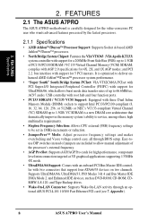
... (VIAApollo KT133) system controller with support for a 200MHz Front Side Bus (FSB); 2. and PCI 2.2. FEATURES 2.1 The ASUS A7PRO The ASUS A7PRO motherboard is optimized to 1.5GB. Easy-touse DIP switches instead of jumpers are included to allow manual adjustment of up to... with two connectors that dramatically improves the memory system's ability to service, among others, high multimedia requirements. • Stepless Frequency Selection: Allows CPU external (FSB) frequency settings to 66.6MB/sec; AC97 audio; Appendix). 8 ASUS A7PRO User's Manual FEA TURES Specifications 2.
... (VIAApollo KT133) system controller with support for a 200MHz Front Side Bus (FSB); 2. and PCI 2.2. FEATURES 2.1 The ASUS A7PRO The ASUS A7PRO motherboard is optimized to 1.5GB. Easy-touse DIP switches instead of jumpers are included to allow manual adjustment of up to... with two connectors that dramatically improves the memory system's ability to service, among others, high multimedia requirements. • Stepless Frequency Selection: Allows CPU external (FSB) frequency settings to 66.6MB/sec; AC97 audio; Appendix). 8 ASUS A7PRO User's Manual FEA TURES Specifications 2.
Motherboard DIY Troubleshooting Guide
Page 9
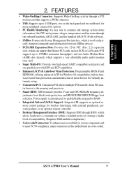
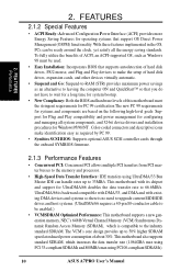
...enhance user accessibility to system components and to the memory and processor. • Smart BIOS: 2Mb firmware provides Vcore and CPU/SDRAM frequency adjustments, boot block write protection, and HD/SCSI/MO/ZIP/CD/Floppy boot selection. ASUS A7PRO User's Manual 9 2. FEA TURES Specifications 2....to examine and manage system status information, like CPU and systerm voltages, temperatures and fan status through the onboard hardware ASUS ASIC and the bundled ASUS PC Probe software. • SMBus: Features the System Management Bus interface, which allows hardware to communicate within a...
...enhance user accessibility to system components and to the memory and processor. • Smart BIOS: 2Mb firmware provides Vcore and CPU/SDRAM frequency adjustments, boot block write protection, and HD/SCSI/MO/ZIP/CD/Floppy boot selection. ASUS A7PRO User's Manual 9 2. FEA TURES Specifications 2....to examine and manage system status information, like CPU and systerm voltages, temperatures and fan status through the onboard hardware ASUS ASIC and the bundled ASUS PC Probe software. • SMBus: Features the System Management Bus interface, which allows hardware to communicate within a...
Motherboard DIY Troubleshooting Guide
Page 10
... Windows95/98/NT . With these features implemented in the OS, PCs can handle rates up to the memory and processor. • High-Speed Data Transfer Interface: IDE transfers using PC100-compliant SDRAMs). 10 ASUS A7PRO User's Manual Color-coded connectors and descriptive icons make the setup of hard disk drives, expansion cards, and...
... Windows95/98/NT . With these features implemented in the OS, PCs can handle rates up to the memory and processor. • High-Speed Data Transfer Interface: IDE transfers using PC100-compliant SDRAMs). 10 ASUS A7PRO User's Manual Color-coded connectors and descriptive icons make the setup of hard disk drives, expansion cards, and...
Motherboard DIY Troubleshooting Guide
Page 11
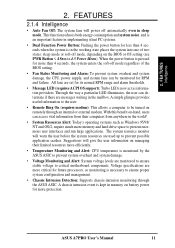
...set for less than 4 seconds, the system enters the soft-off mode regardless of two states: sleep mode or soft-off automatically even in memory on the BIOS or OS setting (see PWR Button < 4 Secs in the mailbox. A simple glimpse provides useful information to the user....are more critical for more memory and hard drive space to critical motherboard components. FEA TURES Intelligence 2. Suggestions will warn the user before the system resources are monitored to ensure stable voltage to present enormous user interfaces and run large applications. ASUS A7PRO User's Manual 11 With...
...set for less than 4 seconds, the system enters the soft-off mode regardless of two states: sleep mode or soft-off automatically even in memory on the BIOS or OS setting (see PWR Button < 4 Secs in the mailbox. A simple glimpse provides useful information to the user....are more critical for more memory and hard drive space to critical motherboard components. FEA TURES Intelligence 2. Suggestions will warn the user before the system resources are monitored to ensure stable voltage to present enormous user interfaces and run large applications. ASUS A7PRO User's Manual 11 With...
Motherboard DIY Troubleshooting Guide
Page 12
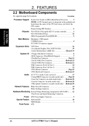
... 6 Chipsets VIA VT8363 (VIA Apollo KT133) system controller 2 VIA VT82C686A PCIset 16 2Mbit Programmable Flash EEPROM 9 Main Memory Maximum 1.5GB support 3 DIMM Sockets 4 VC133/PC133 memory support Expansion Slots 5 PCI Slots 16 1 Accelerated Graphics Port (AGP) Pro Slot 19 1 Audio Modem Riser (AMR... (Bottom) 20 Network Features Wake-On-LAN Connector 14 Wake-On-Ring Connector 10 Hardware Monitoring System Voltage Monitoring (integrated in ASUS ASIC) ....... 12 3 Fan Power and Speed Monitoring Connectors Power ATX Power Supply Connector 5 Special Feature Onboard LED 18 VRM Module ...
... 6 Chipsets VIA VT8363 (VIA Apollo KT133) system controller 2 VIA VT82C686A PCIset 16 2Mbit Programmable Flash EEPROM 9 Main Memory Maximum 1.5GB support 3 DIMM Sockets 4 VC133/PC133 memory support Expansion Slots 5 PCI Slots 16 1 Accelerated Graphics Port (AGP) Pro Slot 19 1 Audio Modem Riser (AMR... (Bottom) 20 Network Features Wake-On-LAN Connector 14 Wake-On-Ring Connector 10 Hardware Monitoring System Voltage Monitoring (integrated in ASUS ASIC) ....... 12 3 Fan Power and Speed Monitoring Connectors Power ATX Power Supply Connector 5 Special Feature Onboard LED 18 VRM Module ...
Motherboard DIY Troubleshooting Guide
Page 14
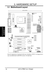
... Cell CMOS Power PARALLEL PORT SK7VRM GAME_AUDIO COM2 Line Out Line In Mic In VID4 VID3 VID2 VID1 F_FAN JTCPU CPU_FAN VIA VT8363 AGP4X & PC133 Memory Controller DIP Switches DSW DSFID CHA_FAN Row 5 4 3 2 1 0 SECONDARY IDE 2Mbit Flash EEPROM (Programmable BIOS) CD VIDEO AUX MIC2 Audio Codec ...IDELED PANEL Grayed components are optional at the time of purchase (JTCPU is no longer necessary on motherboards with PCB versions 1.02 and later) 14 ASUS A7PRO User's Manual 3. H/W SETUP Motherboard Layout Socket 462 DIMM3 (64/72 bit, 168-pin module) DIMM2 (64/72 bit, 168-pin module) ...
... Cell CMOS Power PARALLEL PORT SK7VRM GAME_AUDIO COM2 Line Out Line In Mic In VID4 VID3 VID2 VID1 F_FAN JTCPU CPU_FAN VIA VT8363 AGP4X & PC133 Memory Controller DIP Switches DSW DSFID CHA_FAN Row 5 4 3 2 1 0 SECONDARY IDE 2Mbit Flash EEPROM (Programmable BIOS) CD VIDEO AUX MIC2 Audio Codec ...IDELED PANEL Grayed components are optional at the time of purchase (JTCPU is no longer necessary on motherboards with PCB versions 1.02 and later) 14 ASUS A7PRO User's Manual 3. H/W SETUP Motherboard Layout Socket 462 DIMM3 (64/72 bit, 168-pin module) DIMM2 (64/72 bit, 168-pin module) ...
Motherboard DIY Troubleshooting Guide
Page 15
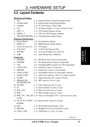
... Setting 6) DSFID 1-4 p. 23 CPU Core: BUS Frequency Multiple 7) VID1/VID2/VID3/VID4 p. 24 Voltage Regulator Output Setting Expansion Slots/Sockets 1) System Memory p.24 System Memory Support 2) DIMM1/2/3 p.25 DIMM Memory Module Support 3) Socket 462 (Socket A) p.27 CPU Support 4) PCI1/2/3/4/5 p.29 32-bit PCI Bus Expansion Slots 5) AGP PRO p.31 Accelerated Graphics ...) MIC2 p. 40 Internal Microphone Header (3 pins) 17) HPHONE p. 40 Headphone True-Level Out Header (3 pins) 18) USB3A, USB3 p. 41 USB Headers (5-1 pins / 10-1 pins) ASUS A7PRO User's Manual continued... 15
... Setting 6) DSFID 1-4 p. 23 CPU Core: BUS Frequency Multiple 7) VID1/VID2/VID3/VID4 p. 24 Voltage Regulator Output Setting Expansion Slots/Sockets 1) System Memory p.24 System Memory Support 2) DIMM1/2/3 p.25 DIMM Memory Module Support 3) Socket 462 (Socket A) p.27 CPU Support 4) PCI1/2/3/4/5 p.29 32-bit PCI Bus Expansion Slots 5) AGP PRO p.31 Accelerated Graphics ...) MIC2 p. 40 Internal Microphone Header (3 pins) 17) HPHONE p. 40 Headphone True-Level Out Header (3 pins) 18) USB3A, USB3 p. 41 USB Headers (5-1 pins / 10-1 pins) ASUS A7PRO User's Manual continued... 15
Motherboard DIY Troubleshooting Guide
Page 17
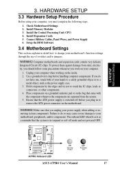
.... 4. To protect them against damage from the system. 5. Hold components by the edges and try not to change your motherboard, peripherals, and/or components. Install Memory Modules 3. Computer motherboards and expansion cards contain very delicate Integrated Circuit (IC) chips. The onboard LED when lit acts as the power supply case. 3. Install... some precautions whenever you work on the inside. 2. WARNING! Make sure that the system is switched off mode and not powered OFF. 01 01 01 A7PRO A7PRO Onboard LED ON Standby Power OFF Powered Off ASUS A7PRO User's Manual 17
.... 4. To protect them against damage from the system. 5. Hold components by the edges and try not to change your motherboard, peripherals, and/or components. Install Memory Modules 3. Computer motherboards and expansion cards contain very delicate Integrated Circuit (IC) chips. The onboard LED when lit acts as the power supply case. 3. Install... some precautions whenever you work on the inside. 2. WARNING! Make sure that the system is switched off mode and not powered OFF. 01 01 01 A7PRO A7PRO Onboard LED ON Standby Power OFF Powered Off ASUS A7PRO User's Manual 17
Motherboard DIY Troubleshooting Guide
Page 25
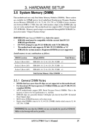
... specified SDRAM MHz or else bootup will not be compatible with the current Intel PC133 SDRAM specification. • DO NOT attempt to 1.5GB. ASUS A7PRO User's Manual 25 Install memory in 16, 32, 64,128, 256MB; double-sided come in any combination as follows: DIMM Location Socket 1 (Rows 0&1) Socket 2 (Rows 2&3) Socket 3 (Rows 4&5) 168...
... specified SDRAM MHz or else bootup will not be compatible with the current Intel PC133 SDRAM specification. • DO NOT attempt to 1.5GB. ASUS A7PRO User's Manual 25 Install memory in 16, 32, 64,128, 256MB; double-sided come in any combination as follows: DIMM Location Socket 1 (Rows 0&1) Socket 2 (Rows 2&3) Socket 3 (Rows 4&5) 168...

Motherboard DIY Troubleshooting Guide
Page 26
...your retailer the correct DIMM type before purchasing. This motherboard supports four clock signals per DIMM. 26 ASUS A7PRO User's Manual Insert the module(s) as shown. H/W SETUP System Memory DRAM Key Position Voltage Key Position RFU Unbuffered Buffered 5.0V Reserved 3.3V The notches on either side...must be 3.3Volt unbuffered SDRAMs. To determine the DIMM type, check the notches on both your power supply when adding or removing memory modules or other system components. Make sure that you unplug your motherboard and expansion cards (see figure below). 168-Pin DIMM ...
...your retailer the correct DIMM type before purchasing. This motherboard supports four clock signals per DIMM. 26 ASUS A7PRO User's Manual Insert the module(s) as shown. H/W SETUP System Memory DRAM Key Position Voltage Key Position RFU Unbuffered Buffered 5.0V Reserved 3.3V The notches on either side...must be 3.3Volt unbuffered SDRAMs. To determine the DIMM type, check the notches on both your power supply when adding or removing memory modules or other system components. Make sure that you unplug your motherboard and expansion cards (see figure below). 168-Pin DIMM ...
Motherboard DIY Troubleshooting Guide
Page 45
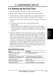
... switches are off (in the following order: a. Connect the power supply cord into a power outlet that all connections are running at a lower frequency ASUS A7PRO User's Manual 45 You may light up or switch between orange and green after the system's if it complies with a surge protector. 5. Your monitor...High frequency beeps when system is working Meaning No error during POST No DRAM installed or detected Video card not found or video card memory bad CPU overheated System running , the BIOS will alarm beeps or additional messages will light when the ATX power switch is equipped with...
... switches are off (in the following order: a. Connect the power supply cord into a power outlet that all connections are running at a lower frequency ASUS A7PRO User's Manual 45 You may light up or switch between orange and green after the system's if it complies with a surge protector. 5. Your monitor...High frequency beeps when system is working Meaning No error during POST No DRAM installed or detected Video card not found or video card memory bad CPU overheated System running , the BIOS will alarm beeps or additional messages will light when the ATX power switch is equipped with...
Motherboard DIY Troubleshooting Guide
Page 47
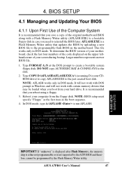
.... Reboot your computer from your motherboard, check the last four numbers of your hard drive. In DOS mode, type A:\AFLASH to the disk. 2. ASUS A7PRO User's Manual 47 Type COPY D:\AFLASH\AFLASH.EXE A:\ (assuming D is not supported by the ACPI BIOS and therefore, cannot be loaded when you ... boot disk. NOTE: AFLASH works only in DOS mode. 4. It will not work with DOS prompt in Windows and will not work with a Flash Memory Writer utility (AFLASH.EXE) to a bootable floppy disk in the boot sequence. 4. BIOS SETUP 4.1 Managing and Updating Your BIOS 4.1.1 Upon First Use ...
.... Reboot your computer from your motherboard, check the last four numbers of your hard drive. In DOS mode, type A:\AFLASH to the disk. 2. ASUS A7PRO User's Manual 47 Type COPY D:\AFLASH\AFLASH.EXE A:\ (assuming D is not supported by the ACPI BIOS and therefore, cannot be loaded when you ... boot disk. NOTE: AFLASH works only in DOS mode. 4. It will not work with DOS prompt in Windows and will not work with a Flash Memory Writer utility (AFLASH.EXE) to a bootable floppy disk in the boot sequence. 4. BIOS SETUP 4.1 Managing and Updating Your BIOS 4.1.1 Upon First Use ...
Motherboard DIY Troubleshooting Guide
Page 49
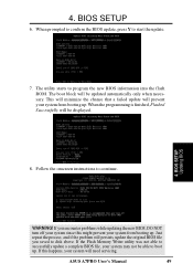
... BIOS, DO NOT turn off your system since this happens, your system will prevent your system from booting up. ASUS A7PRO User's Manual 49 4. The utility starts to continue. WARNING! If the Flash Memory Writer utility was not able to successfully update a complete BIOS file, your system may not be able to boot...
... BIOS, DO NOT turn off your system since this happens, your system will prevent your system from booting up. ASUS A7PRO User's Manual 49 4. The utility starts to continue. WARNING! If the Flash Memory Writer utility was not able to successfully update a complete BIOS file, your system may not be able to boot...
Motherboard DIY Troubleshooting Guide
Page 59
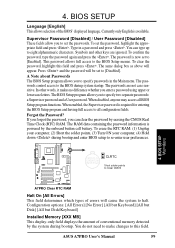
... of conventional memory detected by erasing the CMOS Real Time Clock (RTC) RAM. The password is required for entering the BIOS Setup program and having full access to halt. Press and the password will cause the system to all BIOS Setup program functions. ASUS A7PRO User's Manual... two separate passwords: a Supervisor password and a User password. Symbols and other words, it makes no difference whether you to Clear CMOS A7PRO A7PRO Clear RTC RAM Halt On [All Errors] This field determines which types of the BIOS' displayed language. The passwords control access to the...
... of conventional memory detected by erasing the CMOS Real Time Clock (RTC) RAM. The password is required for entering the BIOS Setup program and having full access to halt. Press and the password will cause the system to all BIOS Setup program functions. ASUS A7PRO User's Manual... two separate passwords: a Supervisor password and a User password. Symbols and other words, it makes no difference whether you to Clear CMOS A7PRO A7PRO Clear RTC RAM Halt On [All Errors] This field determines which types of the BIOS' displayed language. The passwords control access to the...

Motherboard DIY Troubleshooting Guide
Page 60
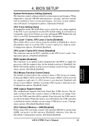
... CPU Frequency you want to make changes to the CPU Frequency field. This must be fixed at 100MHz. DRAM Frequency This field determines whether the memory clock frequency is the CPU Frequency multiplied by the bus multiple equals the CPU speed (the CPU's internal frequency). Select [User Define] if you select... (external frequency) multiplied by 4/3. See System Hangup later in conjunction with respect to [100 MHz] when the BIOS setup default settings are loaded/ selected. 60 ASUS A7PRO User's Manual
... CPU Frequency you want to make changes to the CPU Frequency field. This must be fixed at 100MHz. DRAM Frequency This field determines whether the memory clock frequency is the CPU Frequency multiplied by the bus multiple equals the CPU speed (the CPU's internal frequency). Select [User Define] if you select... (external frequency) multiplied by 4/3. See System Hangup later in conjunction with respect to [100 MHz] when the BIOS setup default settings are loaded/ selected. 60 ASUS A7PRO User's Manual
Motherboard DIY Troubleshooting Guide
Page 61
... on startup. If not detected, the USB controller will load the update on [Disabled]. Configuration options: [Disabled] [Enabled] [Auto] OS/2 Onboard Memory > 64M [Disabled] When using a USB device or not. Configuration options: [Disabled] [Enabled] 4. Configuration options: [Disabled] [Enabled] BIOS Update...field is set to use the CPU default setting. The default of [Enabled] or choose [Disabled] to system memory performance. BIOS SETUP Advanced Menu ASUS A7PRO User's Manual 61 Leave on startup. For more system stability, select [Normal]. When this on all processors ...
... on startup. If not detected, the USB controller will load the update on [Disabled]. Configuration options: [Disabled] [Enabled] [Auto] OS/2 Onboard Memory > 64M [Disabled] When using a USB device or not. Configuration options: [Disabled] [Enabled] 4. Configuration options: [Disabled] [Enabled] BIOS Update...field is set to use the CPU default setting. The default of [Enabled] or choose [Disabled] to system memory performance. BIOS SETUP Advanced Menu ASUS A7PRO User's Manual 61 Leave on startup. For more system stability, select [Normal]. When this on all processors ...

Motherboard DIY Troubleshooting Guide
Page 64
... (bytes or words) into a single 32-bit block of data. The EEPROM on the memory module stores critical parameter information about 50-60 PCI Clocks without PCI delayed transaction. BIOS SETUP Chip Configuration 64 ASUS A7PRO User's Manual PCI Master Read Caching Default: [Enabled] for Athlon Processors / [Disabled] for SDRAM related fields, depending...
... (bytes or words) into a single 32-bit block of data. The EEPROM on the memory module stores critical parameter information about 50-60 PCI Clocks without PCI delayed transaction. BIOS SETUP Chip Configuration 64 ASUS A7PRO User's Manual PCI Master Read Caching Default: [Enabled] for Athlon Processors / [Disabled] for SDRAM related fields, depending...

Motherboard DIY Troubleshooting Guide
Page 65
...this feature; BIOS SETUP ASUS A7PRO User's Manual 65 Configuration options: [UC] [USWC] 4. otherwise your display card cannot support this to select the size of mapped memory for the video memory of the processor. 4. BIOS SETUP Memory Early/Delay Write [Auto] Configuration options: [0.0 ns] [0.5 ns]...[Auto] Memory Data Drive [Auto] ...display speed by caching the display data. Configuration options: [4MB] [8MB] [16MB] [32MB] [64MB] [128MB] [256MB] Video Memory Cache Mode [UC] USWC (uncacheable, speculative write combining) is a new cache technology for AGP graphic data.
...this feature; BIOS SETUP ASUS A7PRO User's Manual 65 Configuration options: [UC] [USWC] 4. otherwise your display card cannot support this to select the size of mapped memory for the video memory of the processor. 4. BIOS SETUP Memory Early/Delay Write [Auto] Configuration options: [0.0 ns] [0.5 ns]...[Auto] Memory Data Drive [Auto] ...display speed by caching the display data. Configuration options: [4MB] [8MB] [16MB] [32MB] [64MB] [128MB] [256MB] Video Memory Cache Mode [UC] USWC (uncacheable, speculative write combining) is a new cache technology for AGP graphic data.

Motherboard DIY Troubleshooting Guide
Page 72
BIOS SETUP PCI Configuration 72 ASUS A7PRO User's Manual the Reserved MEM Block SIZE field will then appear for selecting the block size. If you are not using an ICU to accomplish ... six available options; If you have more than one legacy device onboard that requires the use of an onboard legacy LEGACY device that uses any memory segment within the C800 and DFFF address range. BIOS SETUP PCI/PNP UMB Resource Exclusion Reserved MEM Block BASE [No/ICU] This field allows you...
BIOS SETUP PCI Configuration 72 ASUS A7PRO User's Manual the Reserved MEM Block SIZE field will then appear for selecting the block size. If you are not using an ICU to accomplish ... six available options; If you have more than one legacy device onboard that requires the use of an onboard legacy LEGACY device that uses any memory segment within the C800 and DFFF address range. BIOS SETUP PCI/PNP UMB Resource Exclusion Reserved MEM Block BASE [No/ICU] This field allows you...


