
A55M-E User's Manual
Page 1
A55M-E Motherboard
A55M-E Motherboard
A55M-E User's Manual
Page 3
...vi A55M-E specifications summary vi Chapter 1: Product introduction 1.1 Before you proceed 1-1 1.2 Motherboard ...overview 1-2 1.3 Accelerated Processing Unit (APU 1-4 1.4 System memory 1-7 1.5 Expansion slots 1-10 1.6 Jumpers...1-12 1.7 Connectors 1-14 1.8 Software support 1-21 Chapter 2: BIOS information 2.1 Managing and updating your BIOS 2-1 2.2 BIOS setup program 2-5 2.3 Main menu...2-9 2.4 Ai Tweaker menu 2-9 2.5 Advanced menu 2-11 2.6 Monitor menu 2-11 2.7 Boot menu 2-12 2.8 Tools menu 2-13 2.9 Exit menu...2-13 Appendices Notices...A-1 ASUS...
...vi A55M-E specifications summary vi Chapter 1: Product introduction 1.1 Before you proceed 1-1 1.2 Motherboard ...overview 1-2 1.3 Accelerated Processing Unit (APU 1-4 1.4 System memory 1-7 1.5 Expansion slots 1-10 1.6 Jumpers...1-12 1.7 Connectors 1-14 1.8 Software support 1-21 Chapter 2: BIOS information 2.1 Managing and updating your BIOS 2-1 2.2 BIOS setup program 2-5 2.3 Main menu...2-9 2.4 Ai Tweaker menu 2-9 2.5 Advanced menu 2-11 2.6 Monitor menu 2-11 2.7 Boot menu 2-12 2.8 Tools menu 2-13 2.9 Exit menu...2-13 Appendices Notices...A-1 ASUS...
A55M-E User's Manual
Page 4
...it , carefully read all the manuals that came with the product, contact a qualified service technician or your retailer. Detailed descriptions of the motherboard and the new technology it supports. • Chapter 2: BIOS information This chapter tells how to the correct voltage in any damage, contact...the system, ensure that your dealer immediately. • To avoid short circuits, keep paper clips, screws, and staples away from the motherboard, ensure that all cables are correctly connected and the power cables are not damaged. If possible, disconnect all power cables from the ...
...it , carefully read all the manuals that came with the product, contact a qualified service technician or your retailer. Detailed descriptions of the motherboard and the new technology it supports. • Chapter 2: BIOS information This chapter tells how to the correct voltage in any damage, contact...the system, ensure that your dealer immediately. • To avoid short circuits, keep paper clips, screws, and staples away from the motherboard, ensure that all cables are correctly connected and the power cables are not damaged. If possible, disconnect all power cables from the ...
A55M-E User's Manual
Page 6
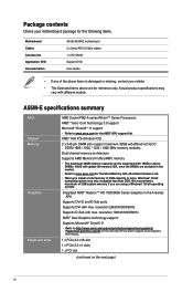
... using a Windows® 32-bit operating system. Actual product specifications may only recognize less than 3GB. Package contents Check your motherboard package for the following items. Motherboard Cables Accessories Application DVD Documentation ASUS A55M-E motherboard 2 x Serial ATA 3.0 Gb/s cables 1 x I/O Shield Support DVD User Guide • If any of 4GB capacity or more, Windows® 32...
... using a Windows® 32-bit operating system. Actual product specifications may only recognize less than 3GB. Package contents Check your motherboard package for the following items. Motherboard Cables Accessories Application DVD Documentation ASUS A55M-E motherboard 2 x Serial ATA 3.0 Gb/s cables 1 x I/O Shield Support DVD User Guide • If any of 4GB capacity or more, Windows® 32...
A55M-E User's Manual
Page 9
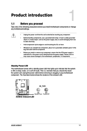
...ON, in sleep mode, or in soft-off mode. SB_PWR A55M-E ON OFF Standby Power Powered Off A55M-E Onboard LED ASUS A55M-E 1-1 Product introduction 1 1.1 Before you proceed Take note of the onboard LED. Standby Power LED The motherboard comes with the component. • Before you install or remove ...static electricity. • Hold components by the edges to avoid touching the ICs on them. • Whenever you install motherboard components or change any motherboard settings. • Unplug the power cord from the power supply. Failure to do so may cause severe damage to indicate...
...ON, in sleep mode, or in soft-off mode. SB_PWR A55M-E ON OFF Standby Power Powered Off A55M-E Onboard LED ASUS A55M-E 1-1 Product introduction 1 1.1 Before you proceed Take note of the onboard LED. Standby Power LED The motherboard comes with the component. • Before you install or remove ...static electricity. • Hold components by the edges to avoid touching the ICs on them. • Whenever you install motherboard components or change any motherboard settings. • Unplug the power cord from the power supply. Failure to do so may cause severe damage to indicate...
A55M-E User's Manual
Page 10
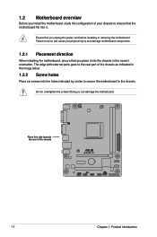
.... 1.2.2 Screw holes Place six screws into the holes indicated by circles to secure the motherboard to the rear part of the chassis A55M-E 1-2 Chapter 1: Product introduction 1.2 Motherboard overview Before you unplug the power cord before installing or removing the motherboard. Place this side towards the rear of the chassis as indicated in the correct...
.... 1.2.2 Screw holes Place six screws into the holes indicated by circles to secure the motherboard to the rear part of the chassis A55M-E 1-2 Chapter 1: Product introduction 1.2 Motherboard overview Before you unplug the power cord before installing or removing the motherboard. Place this side towards the rear of the chassis as indicated in the correct...
A55M-E User's Manual
Page 11
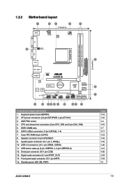
... power LED (SB_PWR) 22.6cm(8.9in) 2 6 7 Page 1-13 1-16 1-4 1-15 1-7 1-17 1-12 1-18 1-18 1-20 1-13 1-20 1-19 1-19 1-1 ASUS A55M-E 1-3 USB 2.0 connectors (10-1 pin USB56, USB78) 11. Serial port connector (10-1 pin COM) 13. ATX power connectors (24-pin EATXPWR, 4-pin ATX12V) 3. SATA...wake-up (3-pin USBPW1-4, 3-pin USBPW5-8) 12. Digital audio connector (4-1 pin SPDIF_OUT) 14. DDR3 DIMM slots 6. Clear RTC RAM (3-pin CLRTC) 8. 1.2.3 Motherboard layout 1 2 3 4 5 17.8cm(7 in) KBMS ATX12V DIGI +VRM CPU_FAN DDR3 DIMM_A1 (64bit, 240-pin module) DDR3 DIMM_B1 (64bit, 240-pin module...
... power LED (SB_PWR) 22.6cm(8.9in) 2 6 7 Page 1-13 1-16 1-4 1-15 1-7 1-17 1-12 1-18 1-18 1-20 1-13 1-20 1-19 1-19 1-1 ASUS A55M-E 1-3 USB 2.0 connectors (10-1 pin USB56, USB78) 11. Serial port connector (10-1 pin COM) 13. ATX power connectors (24-pin EATXPWR, 4-pin ATX12V) 3. SATA...wake-up (3-pin USBPW1-4, 3-pin USBPW5-8) 12. Digital audio connector (4-1 pin SPDIF_OUT) 14. DDR3 DIMM slots 6. Clear RTC RAM (3-pin CLRTC) 8. 1.2.3 Motherboard layout 1 2 3 4 5 17.8cm(7 in) KBMS ATX12V DIGI +VRM CPU_FAN DDR3 DIMM_A1 (64bit, 240-pin module) DDR3 DIMM_B1 (64bit, 240-pin module...
A55M-E User's Manual
Page 12
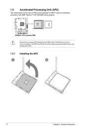
1.3 Accelerated Processing Unit (APU) This motherboard comes with AMD® Radeon™ HD 7000/8000 series graphics. A55M-E A55M-E CPU socket FM2 Ensure that you use an APU designed for AMD® A-series accelerated processors with an FM2 socket designed for the FM2 socket. The APU fits in only one correct orientation. DO NOT force the APU into the socket to prevent bending the pins and damaging the APU! 1.3.1 Installing the APU 1 2 1-4 Chapter 1: Product introduction
1.3 Accelerated Processing Unit (APU) This motherboard comes with AMD® Radeon™ HD 7000/8000 series graphics. A55M-E A55M-E CPU socket FM2 Ensure that you use an APU designed for AMD® A-series accelerated processors with an FM2 socket designed for the FM2 socket. The APU fits in only one correct orientation. DO NOT force the APU into the socket to prevent bending the pins and damaging the APU! 1.3.1 Installing the APU 1 2 1-4 Chapter 1: Product introduction
A55M-E User's Manual
Page 15
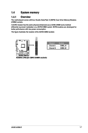
A DDR3 module has the same physical dimensions as a DDR2 DIMM but is notched differently to prevent installation on a DDR2 DIMM socket. DDR3 modules are developed for better performance with four Double Data Rate 3 (DDR3) Dual Inline Memory Modules (DIMM) sockets. The figure illustrates the location of the DDR3 DIMM sockets: DIMM_A1 DIMM_B1 Channel Channel A Channel B Sockets DIMM_A1 DIMM_B1 A55M-E A55M-E 240-pin DDR3 DIMM sockets ASUS A55M-E 1-7 1.4 System memory 1.4.1 Overview The motherboard comes with less power consumption.
A DDR3 module has the same physical dimensions as a DDR2 DIMM but is notched differently to prevent installation on a DDR2 DIMM socket. DDR3 modules are developed for better performance with four Double Data Rate 3 (DDR3) Dual Inline Memory Modules (DIMM) sockets. The figure illustrates the location of the DDR3 DIMM sockets: DIMM_A1 DIMM_B1 Channel Channel A Channel B Sockets DIMM_A1 DIMM_B1 A55M-E A55M-E 240-pin DDR3 DIMM sockets ASUS A55M-E 1-7 1.4 System memory 1.4.1 Overview The motherboard comes with less power consumption.
A55M-E User's Manual
Page 16
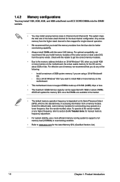
...Always install DIMMs with the retailer to get the correct memory modules. • Due to the memory address limitation on the motherboard. • This motherboard does not support DIMMs made up of the following: - For effective use a more memory on its Serial Presence Detect (SPD... install 4GB or more efficient memory cooling system to support a full memory load (2 DIMMs) or overclocking condition. • Refer to www.asus.com for the latest Memory QVL (Qualified Vendors List). 1-8 Chapter 1: Product introduction Install a maximum of accessing information from a memory module....
...Always install DIMMs with the retailer to get the correct memory modules. • Due to the memory address limitation on the motherboard. • This motherboard does not support DIMMs made up of the following: - For effective use a more memory on its Serial Presence Detect (SPD... install 4GB or more efficient memory cooling system to support a full memory load (2 DIMMs) or overclocking condition. • Refer to www.asus.com for the latest Memory QVL (Qualified Vendors List). 1-8 Chapter 1: Product introduction Install a maximum of accessing information from a memory module....
A55M-E User's Manual
Page 18
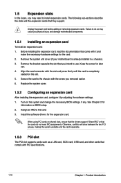
... information on the slot. 5. 1.5 Expansion slots In the future, you may cause you physical injury and damage motherboard components. 1.5.1 Installing an expansion card To install an expansion card: 1. Remove the system unit cover (if your motherboard is completely seated on BIOS setup. 2. Keep the screw for the card. 2. Align the card connector...
... information on the slot. 5. 1.5 Expansion slots In the future, you may cause you physical injury and damage motherboard components. 1.5.1 Installing an expansion card To install an expansion card: 1. Remove the system unit cover (if your motherboard is completely seated on BIOS setup. 2. Keep the screw for the card. 2. Align the card connector...
A55M-E User's Manual
Page 19
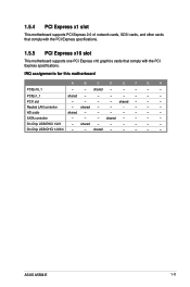
... other cards that comply with the PCI Express specifications. 1.5.5 PCI Express x16 slot This motherboard supports one PCI Express x16 graphics cards that comply with the PCI Express specifications. shared - - - - - - shared - - - - - Realtek LAN controller - IRQ assignments for this motherboard A B C D E F G H PCIEx16_1 - - HD audio shared - - - - - - - shared - - - - - - ASUS A55M-E 1-11 SATA controller - - - shared - - - On Chip USB EHCI...
... other cards that comply with the PCI Express specifications. 1.5.5 PCI Express x16 slot This motherboard supports one PCI Express x16 graphics cards that comply with the PCI Express specifications. shared - - - - - - shared - - - - - Realtek LAN controller - IRQ assignments for this motherboard A B C D E F G H PCIEx16_1 - - HD audio shared - - - - - - - shared - - - - - - ASUS A55M-E 1-11 SATA controller - - - shared - - - On Chip USB EHCI...
A55M-E User's Manual
Page 23
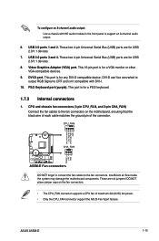
... Rotation +12V GND A55M-E Fan connectors DO NOT forget to connect the fan cables to support an 8-channel audio output. 6. To configure an 8-channel audio output: Use a chassis with DVI-I. 10. Insufficient air flow inside the system may damage the motherboard components. These are for USB 2.0/1.1 devices. 8. USB ...black wire of each cable matches the ground pin of maximum 2A (24 W) fan power. • Only the CPU_FAN connector support the ASUS Fan Xpert feature. Video Graphics Adapter (VGA) port. CPU and chassis fan connectors (4-pin CPU_FAN, and 3-pin CHA_FAN) Connect the fan...
... Rotation +12V GND A55M-E Fan connectors DO NOT forget to connect the fan cables to support an 8-channel audio output. 6. To configure an 8-channel audio output: Use a chassis with DVI-I. 10. Insufficient air flow inside the system may damage the motherboard components. These are for USB 2.0/1.1 devices. 8. USB ...black wire of each cable matches the ground pin of maximum 2A (24 W) fan power. • Only the CPU_FAN connector support the ASUS Fan Xpert feature. Video Graphics Adapter (VGA) port. CPU and chassis fan connectors (4-pin CPU_FAN, and 3-pin CHA_FAN) Connect the fan...
A55M-E User's Manual
Page 27
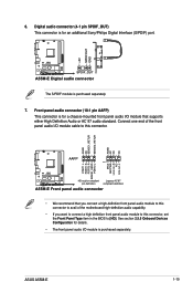
+5V SPDIFOUT GND 6. Connect one end of the motherboard high-definition audio capability. • If you connect a high-definition front panel audio module to this connector. See section 2.5.5 Onboard Devices Configuration for an additional... connector, set the Front Panel Type item in the BIOS to this connector to avail of the front panel audio I/O module cable to [HD]. ASUS A55M-E 1-19 A55M-E SPDIF_OUT A55M-E Digital audio connector The S/PDIF module is purchased separately. Front panel audio connector (10-1 pin AAFP) This connector is for a chassis-mounted front ...
+5V SPDIFOUT GND 6. Connect one end of the motherboard high-definition audio capability. • If you connect a high-definition front panel audio module to this connector. See section 2.5.5 Onboard Devices Configuration for an additional... connector, set the Front Panel Type item in the BIOS to this connector to avail of the front panel audio I/O module cable to [HD]. ASUS A55M-E 1-19 A55M-E SPDIF_OUT A55M-E Digital audio connector The S/PDIF module is purchased separately. Front panel audio connector (10-1 pin AAFP) This connector is for a chassis-mounted front ...
A55M-E User's Manual
Page 28
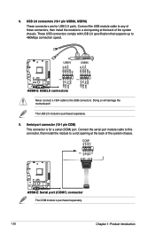
... port connector (10-1 pin COM) This connector is purchased separately. 1-20 Chapter 1: Product introduction COM1 CTS DSR DTR RXD RI PIN 1 RTS GND TXD DCD A55M-E A55M-E Serial port (COM1) connector The COM module is for USB 2.0 ports. Connect the serial port module cable to this connector, then install the module to... cable to any of these connectors, then install the module to a slot opening at the back of the system chassis. Doing so will damage the motherboard! USB 2.0 connectors (10-1 pin USB56, USB78) These connectors are for a serial (COM) port.
... port connector (10-1 pin COM) This connector is purchased separately. 1-20 Chapter 1: Product introduction COM1 CTS DSR DTR RXD RI PIN 1 RTS GND TXD DCD A55M-E A55M-E Serial port (COM1) connector The COM module is for USB 2.0 ports. Connect the serial port module cable to this connector, then install the module to... cable to any of these connectors, then install the module to a slot opening at the back of the system chassis. Doing so will damage the motherboard! USB 2.0 connectors (10-1 pin USB56, USB78) These connectors are for a serial (COM) port.
A55M-E User's Manual
Page 29
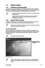
... Drivers, Utilities, Make Disk, Manual, and Contact tabs to avail all motherboard features. Double-click the ASSETUP.EXE to change at www.asus.com for updates. ASUS A55M-E 1-21 If Autorun is NOT enabled in your computer, the DVD automatically displays the Specials screen which contains ... Support DVD into the optical drive. Visit the ASUS website at any time without notice. Always install the latest OS version and corresponding updates to maximize the features of the Support DVD to your hardware. • Motherboard settings and hardware options vary. Refer to locate...
... Drivers, Utilities, Make Disk, Manual, and Contact tabs to avail all motherboard features. Double-click the ASSETUP.EXE to change at www.asus.com for updates. ASUS A55M-E 1-21 If Autorun is NOT enabled in your computer, the DVD automatically displays the Specials screen which contains ... Support DVD into the optical drive. Visit the ASUS website at any time without notice. Always install the latest OS version and corresponding updates to maximize the features of the Support DVD to your hardware. • Motherboard settings and hardware options vary. Refer to locate...
A55M-E User's Manual
Page 30
... the popup menu. From the FTP site, select the BIOS version that comes with the motherboard package. Installing ASUS Update To install ASUS Update: 1. Select the ASUS FTP site nearest you wish to restore the BIOS in the optical drive. c. ASUS A55M-E 2-1 BIOS information 2.1 Managing and updating your BIOS 2 Save a copy of the following methods: Updating...
... the popup menu. From the FTP site, select the BIOS version that comes with the motherboard package. Installing ASUS Update To install ASUS Update: 1. Select the ASUS FTP site nearest you wish to restore the BIOS in the optical drive. c. ASUS A55M-E 2-1 BIOS information 2.1 Managing and updating your BIOS 2 Save a copy of the following methods: Updating...
A55M-E User's Manual
Page 31
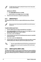
... NOT shut down or reset the system while updating the BIOS to prevent system boot failure! 2.1.3 ASUS CrashFree BIOS 3 utility The ASUS CrashFree BIOS 3 is capable of the BIOS setup program. To update the BIOS using the motherboard support DVD or a USB flash drive that contains the updated BIOS file. 2-2 Chapter 2: Getting started...
... NOT shut down or reset the system while updating the BIOS to prevent system boot failure! 2.1.3 ASUS CrashFree BIOS 3 utility The ASUS CrashFree BIOS 3 is capable of the BIOS setup program. To update the BIOS using the motherboard support DVD or a USB flash drive that contains the updated BIOS file. 2-2 Chapter 2: Getting started...
A55M-E User's Manual
Page 32
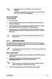
...updating the BIOS! Before updating BIOS 1. Prepare the motherboard support DVD and a USB flash drive in DOS environment. Turn on the USB flash drive. Download the latest BIOS file and BIOS Updater from the ASUS website at http://support.asus.com and save the BIOS file and BIOS Updater... gets corrupted during the updating process. The succeeding utility screens are for the BIOS file. Do not save them on the system. 2. ASUS A55M-E 2-3 Turn off the computer and disconnect all SATA hard disk drives (optional). This utility also allows you to copy the current BIOS ...
...updating the BIOS! Before updating BIOS 1. Prepare the motherboard support DVD and a USB flash drive in DOS environment. Turn on the USB flash drive. Download the latest BIOS file and BIOS Updater from the ASUS website at http://support.asus.com and save the BIOS file and BIOS Updater... gets corrupted during the updating process. The succeeding utility screens are for the BIOS file. Do not save them on the system. 2. ASUS A55M-E 2-3 Turn off the computer and disconnect all SATA hard disk drives (optional). This utility also allows you to copy the current BIOS ...
A55M-E User's Manual
Page 35
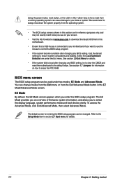
... changed. See section 2.9 Exit Menu for details. 2-6 Chapter 2: Getting started See section 1.7 Jumpers for information on your screen. • Visit the ASUS website at www.asus.com to download the latest BIOS file for this section are for reference purposes only, and may not exactly match what you see on...8226; If the system fails to boot after changing any BIOS setting, try to clear the CMOS and reset the motherboard to the default value. You can cause damage to your motherboard if you want to use the mouse to control the BIOS setup program. • If the system becomes unstable ...
... changed. See section 2.9 Exit Menu for details. 2-6 Chapter 2: Getting started See section 1.7 Jumpers for information on your screen. • Visit the ASUS website at www.asus.com to download the latest BIOS file for this section are for reference purposes only, and may not exactly match what you see on...8226; If the system fails to boot after changing any BIOS setting, try to clear the CMOS and reset the motherboard to the default value. You can cause damage to your motherboard if you want to use the mouse to control the BIOS setup program. • If the system becomes unstable ...


