A55M-E User's Manual
Page 2
.... SPECIFICATIONS AND INFORMATION CONTAINED IN THIS MANUAL ARE FURNISHED FOR INFORMATIONAL USE ONLY, AND ARE SUBJECT TO CHANGE AT ANY TIME WITHOUT NOTICE, AND SHOULD NOT BE CONSTRUED AS A COMMITMENT BY ASUS. Copies of these licenses are used only for which is eager to have it from http://support.asus.com/download or (2) for backup purposes, without the express written...
.... SPECIFICATIONS AND INFORMATION CONTAINED IN THIS MANUAL ARE FURNISHED FOR INFORMATIONAL USE ONLY, AND ARE SUBJECT TO CHANGE AT ANY TIME WITHOUT NOTICE, AND SHOULD NOT BE CONSTRUED AS A COMMITMENT BY ASUS. Copies of these licenses are used only for which is eager to have it from http://support.asus.com/download or (2) for backup purposes, without the express written...
A55M-E User's Manual
Page 4
... need when installing and configuring the motherboard. How this guide This user guide contains the information you encounter technical problems with the package. • Before using the product, ensure all power cables are unplugged. • Seek professional assistance before the signal cables are connected. If possible, disconnect all power cables from connectors, slots, sockets and circuitry. • Avoid dust, humidity, and temperature extremes. About this guide is set to or...
... need when installing and configuring the motherboard. How this guide This user guide contains the information you encounter technical problems with the package. • Before using the product, ensure all power cables are unplugged. • Seek professional assistance before the signal cables are connected. If possible, disconnect all power cables from connectors, slots, sockets and circuitry. • Avoid dust, humidity, and temperature extremes. About this guide is set to or...
A55M-E User's Manual
Page 6
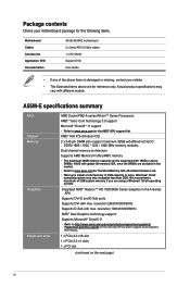
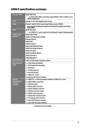
... ASUS A55M-E motherboard 2 x Serial ATA 3.0 Gb/s cables 1 x I/O Shield Support DVD User Guide • If any of 4GB capacity or more, Windows® 32-bit operating system may vary with max. Actual product specifications may only recognize less than 3GB. resolution 1920x1600@60Hz AMD® Dual Graphics technology support* Supports Microsoft® DirectX 11 • Refer to http://www.amd.com/us/products/technologies/dual-graphics/ Pages/dual-graphics.aspx#3 for the AMD® APU support list. A55M-E specifications summary APU Chipset Memory Graphics...
... ASUS A55M-E motherboard 2 x Serial ATA 3.0 Gb/s cables 1 x I/O Shield Support DVD User Guide • If any of 4GB capacity or more, Windows® 32-bit operating system may vary with max. Actual product specifications may only recognize less than 3GB. resolution 1920x1600@60Hz AMD® Dual Graphics technology support* Supports Microsoft® DirectX 11 • Refer to http://www.amd.com/us/products/technologies/dual-graphics/ Pages/dual-graphics.aspx#3 for the AMD® APU support list. A55M-E specifications summary APU Chipset Memory Graphics...
A55M-E User's Manual
Page 7
... support RAID 0, RAID 1, RAID 10 and JBOD configurations Realtek® 8111F PCIe Gigabit LAN controller Realtek® ALC887-VD 8-channel High Definition Audio CODEC • Use a chassis with HD audio module in the front panel to support an 8-channel audio output. A55M-E specifications summary Storage / RAID LAN Audio USB ASUS unique features Special features Back Panel I/O ports Internal I /O ports (3-jack) 2 x USB 2.0/1.1 connectors support additional 4 USB 2.0/1.1 ports 4 x SATA 3.0Gb/s connectors 1 x COM connector 1 x System panel connector 1 x Internal Speaker connector 1 x CPU fan...
... support RAID 0, RAID 1, RAID 10 and JBOD configurations Realtek® 8111F PCIe Gigabit LAN controller Realtek® ALC887-VD 8-channel High Definition Audio CODEC • Use a chassis with HD audio module in the front panel to support an 8-channel audio output. A55M-E specifications summary Storage / RAID LAN Audio USB ASUS unique features Special features Back Panel I/O ports Internal I /O ports (3-jack) 2 x USB 2.0/1.1 connectors support additional 4 USB 2.0/1.1 ports 4 x SATA 3.0Gb/s connectors 1 x COM connector 1 x System panel connector 1 x Internal Speaker connector 1 x CPU fan...
A55M-E User's Manual
Page 9
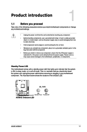
... location of the following precautions before you install motherboard components or change any motherboard settings. • Unplug the power cord from the power supply. SB_PWR A55M-E ON OFF Standby Power Powered Off A55M-E Onboard LED ASUS A55M-E 1-1 This is a reminder that you install or remove any motherboard component. Standby Power LED The motherboard comes with the component. • Before you should shut down the system and unplug the power cable before removing or plugging in soft-off mode. Failure...
... location of the following precautions before you install motherboard components or change any motherboard settings. • Unplug the power cord from the power supply. SB_PWR A55M-E ON OFF Standby Power Powered Off A55M-E Onboard LED ASUS A55M-E 1-1 This is a reminder that you install or remove any motherboard component. Standby Power LED The motherboard comes with the component. • Before you should shut down the system and unplug the power cable before removing or plugging in soft-off mode. Failure...
A55M-E User's Manual
Page 11
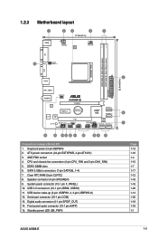
CPU and chassis fan connectors (4-pin CPU_FAN and 3-pin CHA_FAN) 5. System panel connector (10-1 pin F_PANEL) 10. Front panel audio connector (10-1 pin AAFP) 15. Standby power LED (SB_PWR) 22.6cm(8.9in) 2 6 7 Page 1-13 1-16 1-4 1-15 1-7 1-17 1-12 1-18 1-18 1-20 1-13 1-20 1-19 1-19 1-1 ASUS A55M-E 1-3 AMD FM2 socket 4. USB device wake-up (3-pin USBPW1-4, 3-pin USBPW5-8) 12. Serial port connector (10-1 pin COM) 13. 1.2.3 Motherboard layout 1 2 3 4 5 17.8cm(7 in) KBMS ATX12V DIGI +VRM CPU_FAN DDR3 DIMM_A1 (64bit, 240-pin module...
CPU and chassis fan connectors (4-pin CPU_FAN and 3-pin CHA_FAN) 5. System panel connector (10-1 pin F_PANEL) 10. Front panel audio connector (10-1 pin AAFP) 15. Standby power LED (SB_PWR) 22.6cm(8.9in) 2 6 7 Page 1-13 1-16 1-4 1-15 1-7 1-17 1-12 1-18 1-18 1-20 1-13 1-20 1-19 1-19 1-1 ASUS A55M-E 1-3 AMD FM2 socket 4. USB device wake-up (3-pin USBPW1-4, 3-pin USBPW5-8) 12. Serial port connector (10-1 pin COM) 13. 1.2.3 Motherboard layout 1 2 3 4 5 17.8cm(7 in) KBMS ATX12V DIGI +VRM CPU_FAN DDR3 DIMM_A1 (64bit, 240-pin module...
A55M-E User's Manual
Page 16
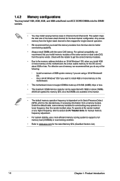
Under the default state, some memory modules for overclocking may install varying memory sizes in the market. • The default memory operation frequency is dependent on the motherboard. • This motherboard does not support DIMMs made up of 512Mb (64MB) chips or less. • The maximum 32GB memory capacity can be supported with 16GB or above DIMMs. ASUS will update the memory QVL once the DIMMs are using a 32-bit Windows®...
Under the default state, some memory modules for overclocking may install varying memory sizes in the market. • The default memory operation frequency is dependent on the motherboard. • This motherboard does not support DIMMs made up of 512Mb (64MB) chips or less. • The maximum 32GB memory capacity can be supported with 16GB or above DIMMs. ASUS will update the memory QVL once the DIMMs are using a 32-bit Windows®...
A55M-E User's Manual
Page 18
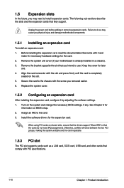
... expansion card. Unplug the power cord before adding or removing expansion cards. Failure to do not need to the card. 3. Turn on shared slots, ensure that the drivers support "Share IRQ" or that the cards do so may need IRQ assignments. Replace the system cover. 1.5.2 Configuring an expansion card After installing the expansion card, configure it and make the necessary hardware settings for later use . Align the card connector with PCI specifications. 1-10...
... expansion card. Unplug the power cord before adding or removing expansion cards. Failure to do not need to the card. 3. Turn on shared slots, ensure that the drivers support "Share IRQ" or that the cards do so may need IRQ assignments. Replace the system cover. 1.5.2 Configuring an expansion card After installing the expansion card, configure it and make the necessary hardware settings for later use . Align the card connector with PCI specifications. 1-10...
A55M-E User's Manual
Page 19
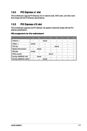
...- - - HD audio shared - - - - - - - SATA controller - - - On Chip USB EHCI 1/2/3 - shared - - - - - - On Chip USB OHCI 1/2/3/4 - - 1.5.4 PCI Express x1 slot This motherboard supports PCI Express 2.0 x1 network cards, SCSI cards, and other cards that comply with the PCI Express specifications. 1.5.5 PCI Express x16 slot This motherboard supports one PCI Express x16 graphics cards that comply with the PCI Express specifications. PCIEx1_1 shared - - - - - - - shared - - - - - - PCI1 slot - - - - Realtek LAN controller - ASUS A55M-E 1-11 shared...
...- - - HD audio shared - - - - - - - SATA controller - - - On Chip USB EHCI 1/2/3 - shared - - - - - - On Chip USB OHCI 1/2/3/4 - - 1.5.4 PCI Express x1 slot This motherboard supports PCI Express 2.0 x1 network cards, SCSI cards, and other cards that comply with the PCI Express specifications. 1.5.5 PCI Express x16 slot This motherboard supports one PCI Express x16 graphics cards that comply with the PCI Express specifications. PCIEx1_1 shared - - - - - - - shared - - - - - - PCI1 slot - - - - Realtek LAN controller - ASUS A55M-E 1-11 shared...

A55M-E User's Manual
Page 20
.... 4. A55M-E A55M-E Clear RTC RAM CLRTC 12 23 Normal (Default) Clear RTC To erase the RTC RAM: 1. Turn OFF the computer and unplug the power cord. 2. Hold down and reboot the system, then the BIOS automatically resets parameter settings to reenter data. You can clear the CMOS memory of date, time, and system setup parameters by erasing the CMOS RTC RAM data. Move the jumper cap from pins 1-2 (default) to overclocking, use the CPU...
.... 4. A55M-E A55M-E Clear RTC RAM CLRTC 12 23 Normal (Default) Clear RTC To erase the RTC RAM: 1. Turn OFF the computer and unplug the power cord. 2. Hold down and reboot the system, then the BIOS automatically resets parameter settings to reenter data. You can clear the CMOS memory of date, time, and system setup parameters by erasing the CMOS RTC RAM data. Move the jumper cap from pins 1-2 (default) to overclocking, use the CPU...
A55M-E User's Manual
Page 21
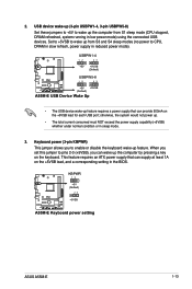
Set to +5VSB to wake up from S1 sleep mode (CPU stopped, DRAM refreshed, system running in the BIOS. A55M-E KBPWR 12 +5V (Default) 23 +5VSB A55M-E Keyboard power setting ASUS A55M-E 1-13 When you set this jumper to pins 2-3 (+5VSB), you to enable or disable the keyboard wake-up the computer from S3 and S4 sleep modes (no power to wake up feature. This feature requires an ATX power supply that can provide 500mA on the keyboard. otherwise, the system...
Set to +5VSB to wake up from S1 sleep mode (CPU stopped, DRAM refreshed, system running in the BIOS. A55M-E KBPWR 12 +5V (Default) 23 +5VSB A55M-E Keyboard power setting ASUS A55M-E 1-13 When you set this jumper to pins 2-3 (+5VSB), you to enable or disable the keyboard wake-up the computer from S3 and S4 sleep modes (no power to wake up feature. This feature requires an ATX power supply that can provide 500mA on the keyboard. otherwise, the system...
A55M-E User's Manual
Page 23
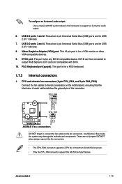
... pin of maximum 2A (24 W) fan power. • Only the CPU_FAN connector support the ASUS Fan Xpert feature. To configure an 8-channel audio output: Use a chassis with DVI-I. 10. Video Graphics Adapter (VGA) port. DVI-D can't be converted to output RGB Signal to CRT and isn't compatible with HD audio module in the front panel to the fan connectors. PS/2 Keyboard port (purple). These are for a PS/2 keyboard. 1.7.2 Internal connectors 1. ASUS A55M-E 1-15 This port is for USB 2.0/1.1 devices. 7. CPU_FAN CPU FAN PWM CPU FAN...
... pin of maximum 2A (24 W) fan power. • Only the CPU_FAN connector support the ASUS Fan Xpert feature. To configure an 8-channel audio output: Use a chassis with DVI-I. 10. Video Graphics Adapter (VGA) port. DVI-D can't be converted to output RGB Signal to CRT and isn't compatible with HD audio module in the front panel to the fan connectors. PS/2 Keyboard port (purple). These are for a PS/2 keyboard. 1.7.2 Internal connectors 1. ASUS A55M-E 1-15 This port is for USB 2.0/1.1 devices. 7. CPU_FAN CPU FAN PWM CPU FAN...
A55M-E User's Manual
Page 25
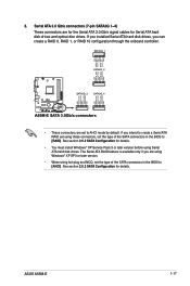
... hard disk drives and optical disc drives. 3. ASUS A55M-E 1-17 Serial ATA 3.0 Gb/s connectors (7-pin SATA3G 1~4) These connectors are using Windows® XP SP3 or later version. • When using Serial ATA hard disk drives. If you can create a RAID 0, RAID 1, or RAID 10 configuration through the onboard controller. See section 2.5.2 SATA Configuration for details. • You must install Windows® XP Service Pack 3 or later version before using hot-plug and NCQ, set the type of the SATA connectors in the BIOS to [RAID]. If you installed Serial ATA hard disk drives...
... hard disk drives and optical disc drives. 3. ASUS A55M-E 1-17 Serial ATA 3.0 Gb/s connectors (7-pin SATA3G 1~4) These connectors are using Windows® XP SP3 or later version. • When using Serial ATA hard disk drives. If you can create a RAID 0, RAID 1, or RAID 10 configuration through the onboard controller. See section 2.5.2 SATA Configuration for details. • You must install Windows® XP Service Pack 3 or later version before using hot-plug and NCQ, set the type of the SATA connectors in the BIOS to [RAID]. If you installed Serial ATA hard disk drives...
A55M-E User's Manual
Page 27
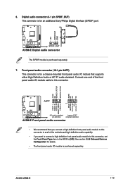
... A55M-E Digital audio connector The S/PDIF module is for a chassis-mounted front panel audio I/O module that you connect a high-definition front panel audio module to this connector. See section 2.5.5 Onboard Devices Configuration for an additional Sony/Philips Digital Interface (S/PDIF) port. Digital audio connector (4-1 pin SPDIF_OUT) This connector is purchased separately. Connect one end of the motherboard high-definition audio capability. • If you want to connect a high definition front panel audio module to this connector, set the Front Panel Type...
... A55M-E Digital audio connector The S/PDIF module is for a chassis-mounted front panel audio I/O module that you connect a high-definition front panel audio module to this connector. See section 2.5.5 Onboard Devices Configuration for an additional Sony/Philips Digital Interface (S/PDIF) port. Digital audio connector (4-1 pin SPDIF_OUT) This connector is purchased separately. Connect one end of the motherboard high-definition audio capability. • If you want to connect a high definition front panel audio module to this connector, set the Front Panel Type...
A55M-E User's Manual
Page 29
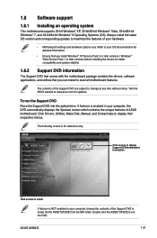
... DVD. Always install the latest OS version and corresponding updates to maximize the features of the Support DVD to change at www.asus.com for updates. The following screen is enabled in your computer, browse the contents of your hardware. • Motherboard settings and hardware options vary. 1.8 Software support 1.8.1 Installing an operating system This motherboard supports 32-bit Windows® XP, 32-bit/64-bit Windows® Vista, 32-bit/64-bit Windows® 7, and 32-bit/64-bit Windows...
... DVD. Always install the latest OS version and corresponding updates to maximize the features of the Support DVD to change at www.asus.com for updates. The following screen is enabled in your computer, browse the contents of your hardware. • Motherboard settings and hardware options vary. 1.8 Software support 1.8.1 Installing an operating system This motherboard supports 32-bit Windows® XP, 32-bit/64-bit Windows® Vista, 32-bit/64-bit Windows® 7, and 32-bit/64-bit Windows...
A55M-E User's Manual
Page 30
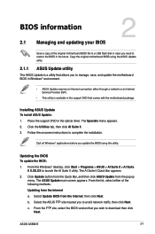
... original motherboard BIOS file to a USB flash disk in case you need to restore the BIOS in the optical drive. From the Windows® desktop, click Start > Programs > ASUS > AI Suite II > AI Suite II X.XX.XX to complete the installation. Place the support DVD in the future. Click Update button from the Quick Bar, and then click ASUS Update from the Internet, then click Next. The ASUS Update main screen appears. ASUS A55M-E 2-1 From the list...
... original motherboard BIOS file to a USB flash disk in case you need to restore the BIOS in the optical drive. From the Windows® desktop, click Start > Programs > ASUS > AI Suite II > AI Suite II X.XX.XX to complete the installation. Place the support DVD in the future. Click Update button from the Quick Bar, and then click ASUS Update from the Internet, then click Next. The ASUS Update main screen appears. ASUS A55M-E 2-1 From the list...
A55M-E User's Manual
Page 31
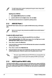
... while updating the BIOS to prevent system boot failure! 2.1.3 ASUS CrashFree BIOS 3 utility The ASUS CrashFree BIOS 3 is capable of the BIOS setup program. Always update the utility to the Folder Info field. 6. Enter the Advanced Mode of updating itself through the Internet. Press to switch to avail all its features. Press the Up/Down arrow keys to find the BIOS file, and then press to update the BIOS without using the motherboard support DVD or a USB flash drive...
... while updating the BIOS to prevent system boot failure! 2.1.3 ASUS CrashFree BIOS 3 utility The ASUS CrashFree BIOS 3 is capable of the BIOS setup program. Always update the utility to the Folder Info field. 6. Enter the Advanced Mode of updating itself through the Internet. Press to switch to avail all its features. Press the Up/Down arrow keys to find the BIOS file, and then press to update the BIOS without using the motherboard support DVD or a USB flash drive...
A55M-E User's Manual
Page 32
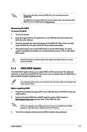
... SATA hard disk drives (optional). ASUS A55M-E 2-3 Insert the support DVD to the optical drive or the USB flash drive that you press to load default BIOS values. To ensure system compatibility and stability, we recommend that contains the BIOS file to update BIOS in DOS environment. Doing so can use as shown. This utility also allows you to copy the current BIOS file that you can cause system boot failure! 2.1.4 ASUS BIOS Updater The ASUS BIOS Updater allows you to enter BIOS Setup to a hard disk drive or USB flash drive...
... SATA hard disk drives (optional). ASUS A55M-E 2-3 Insert the support DVD to the optical drive or the USB flash drive that you press to load default BIOS values. To ensure system compatibility and stability, we recommend that contains the BIOS file to update BIOS in DOS environment. Doing so can use as shown. This utility also allows you to copy the current BIOS file that you can cause system boot failure! 2.1.4 ASUS BIOS Updater The ASUS BIOS Updater allows you to enter BIOS Setup to a hard disk drive or USB flash drive...
A55M-E User's Manual
Page 33
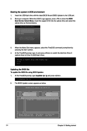
... the USB flash drive with the latest BIOS file and BIOS Updater to show the BIOS Boot Device Select Menu. Insert the support DVD into the optical drive and select the optical drive as below. At the FreeDOS prompt, type d: and press to switch the disk from Drive C (optical drive) to Drive D (USB flash drive). The BIOS Updater screen appears as the boot device. 3. Boot your computer. At the FreeDOS prompt, type bupdater /pc /g and press . 2. ASUSTek BIOS Updater for DOS V1.30 BOARD: A55M...
... the USB flash drive with the latest BIOS file and BIOS Updater to show the BIOS Boot Device Select Menu. Insert the support DVD into the optical drive and select the optical drive as below. At the FreeDOS prompt, type d: and press to switch the disk from Drive C (optical drive) to Drive D (USB flash drive). The BIOS Updater screen appears as the boot device. 3. Boot your computer. At the FreeDOS prompt, type bupdater /pc /g and press . 2. ASUSTek BIOS Updater for DOS V1.30 BOARD: A55M...
A55M-E User's Manual
Page 34
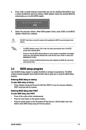
... Load Optimized Defaults item under the Exit menu. The BIOS screens include navigation keys and brief online help to update the BIOS or configure its routines. Refer to section 2.9 Exit menu for details. • Ensure to connect all SATA hard disk drives after updating the BIOS file if you have disconnected them. 2.2 BIOS setup program Use the BIOS Setup program to guide you failed to select the BIOS file and press . 3. DO NOT shut down or reset...
... Load Optimized Defaults item under the Exit menu. The BIOS screens include navigation keys and brief online help to update the BIOS or configure its routines. Refer to section 2.9 Exit menu for details. • Ensure to connect all SATA hard disk drives after updating the BIOS file if you have disconnected them. 2.2 BIOS setup program Use the BIOS Setup program to guide you failed to select the BIOS file and press . 3. DO NOT shut down or reset...


