Owners Manual
Page 4
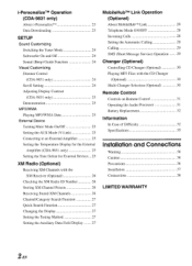
...Setting the Temperature Display for the External Amplifier (CDA-9831 only) 25 Setting the Tone Defeat for External Devices 25 XM Radio (Optional) Receiving XM Channels with the XM Receiver (Optional) 26 Checking the XM Radio ID Number 26 Storing XM Channel Presets 26 ... SMS (Short Message Service) Operation 29 Changer (Optional) Controlling CD Changer (Optional) 30 Playing MP3 Files with the CD Changer (Optional) 30 Multi-Changer Selection (Optional) 30 Remote Control Controls on Remote Control 31 Operating the Audio Processor 31 Battery Replacement 32 Information ...
...Setting the Temperature Display for the External Amplifier (CDA-9831 only) 25 Setting the Tone Defeat for External Devices 25 XM Radio (Optional) Receiving XM Channels with the XM Receiver (Optional) 26 Checking the XM Radio ID Number 26 Storing XM Channel Presets 26 ... SMS (Short Message Service) Operation 29 Changer (Optional) Controlling CD Changer (Optional) 30 Playing MP3 Files with the CD Changer (Optional) 30 Multi-Changer Selection (Optional) 30 Remote Control Controls on Remote Control 31 Operating the Audio Processor 31 Battery Replacement 32 Information ...
Owners Manual
Page 28
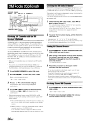
... XM3, press 1-41 or HI to select channel "0." The unit alternately displays "RADIO ID" for 2 seconds, then the ID number for your desired satellite channel in XM mode. 1 Press SOURCE/POWER to the CDA-9831/CDA-9830. Storing XM Channel Presets 1 Press BAND/TEL. to select desired category. Each... down ♦ or ♦ will be cleared and replaced with the numeric keypad on the remote control. 2 Press ENTER or + 10/OK on the screen of the remote control. 1 While in XM Radio mode, enter the Channel number you store a channel in a preset memory which you want to...
... XM3, press 1-41 or HI to select channel "0." The unit alternately displays "RADIO ID" for 2 seconds, then the ID number for your desired satellite channel in XM mode. 1 Press SOURCE/POWER to the CDA-9831/CDA-9830. Storing XM Channel Presets 1 Press BAND/TEL. to select desired category. Each... down ♦ or ♦ will be cleared and replaced with the numeric keypad on the remote control. 2 Press ENTER or + 10/OK on the screen of the remote control. 1 While in XM Radio mode, enter the Channel number you store a channel in a preset memory which you want to...
Owners Manual
Page 32
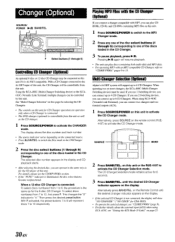
...) Alpine's Ai-NET system will be connected to 12 respectively. When using KCA-410C, see the CD/MP3/WMA section. • If the "FUNC" indicator is Ai-NET compatible. SOURCE BAND 2 Press BAND/TEL. until the desired changer indicator appears on the display. on the Remote Control...you can connect up to 13. F Select buttons (1 through 6) corresponding to one of this unit as well as for CDA-9830). • To operate the selected changer, see "CD/MP3/WMA"(page 9). • Forfurther details about the external input (AUX) when using KCA-410C (Versatile Link Terminal), ...
...) Alpine's Ai-NET system will be connected to 12 respectively. When using KCA-410C, see the CD/MP3/WMA section. • If the "FUNC" indicator is Ai-NET compatible. SOURCE BAND 2 Press BAND/TEL. until the desired changer indicator appears on the display. on the Remote Control...you can connect up to 13. F Select buttons (1 through 6) corresponding to one of this unit as well as for CDA-9830). • To operate the selected changer, see "CD/MP3/WMA"(page 9). • Forfurther details about the external input (AUX) when using KCA-410C (Versatile Link Terminal), ...

Owners Manual
Page 40
...14 O 0 e 18 e orb 000 131 Speakers Front right a (I Rear right ) (I . Connections -7' II I To amplifier (CDA-9831 only) Blue POWER ANT Blue/White REMOTE TURN-ON AUDIO Pink/Black INTERRUPT IN r Orange ILLUMINATION Red IGNITION Yellow BATTERY Black GND Antenna To power antenna To amplifier or equalizer To ... cluster illumination lead (CDA-9831 only) Ignition Key e Battery 14_ Ai-NET OD NORM EQ/DIV *1 Gray SPEAKER RIGHT FRONT Gray/Black Violet/Black 'SPEAKER RIGHT REAR Violet Green SPEAKER LEFT REAR Green/Black White/Black I Rear left Front left CD Changer (Sold Separately)...
...14 O 0 e 18 e orb 000 131 Speakers Front right a (I Rear right ) (I . Connections -7' II I To amplifier (CDA-9831 only) Blue POWER ANT Blue/White REMOTE TURN-ON AUDIO Pink/Black INTERRUPT IN r Orange ILLUMINATION Red IGNITION Yellow BATTERY Black GND Antenna To power antenna To amplifier or equalizer To ... cluster illumination lead (CDA-9831 only) Ignition Key e Battery 14_ Ai-NET OD NORM EQ/DIV *1 Gray SPEAKER RIGHT FRONT Gray/Black Violet/Black 'SPEAKER RIGHT REAR Violet Green SPEAKER LEFT REAR Green/Black White/Black I Rear left Front left CD Changer (Sold Separately)...
Owners Manual
Page 41
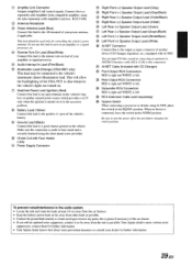
...Black) Connect this lead to the remote turn-on an amplifier, or a signal processor, etc. ® Remote Turn-On Lead (Blue/White) Connect...CD Changer) O Front Output RCA Connectors RED is right and WHITE is left . When no device is securely fastened using the (also separately sold separately) O System Switch When connecting a processor or divider using Ai-NET, place this lead to the unit before changing the switch position. Your Alpine...Audio Interrupt In Lead (Pink/Black) 0 Illumination Lead (Orange) (CDA-9831 only) This lead may be used onlyfor controlling the vehicle's power ...
...Black) Connect this lead to the remote turn-on an amplifier, or a signal processor, etc. ® Remote Turn-On Lead (Blue/White) Connect...CD Changer) O Front Output RCA Connectors RED is right and WHITE is left . When no device is securely fastened using the (also separately sold separately) O System Switch When connecting a processor or divider using Ai-NET, place this lead to the unit before changing the switch position. Your Alpine...Audio Interrupt In Lead (Pink/Black) 0 Illumination Lead (Orange) (CDA-9831 only) This lead may be used onlyfor controlling the vehicle's power ...


