
X223W LCD Monitor User's Guide
Page 16
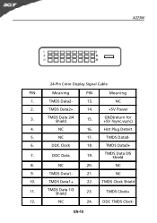
NC 17. TMDS Data0- 6. NC 9. TMDS Data1- 21. TMDS Data 1/3 Shield 23. TMDS Data2- 13. TMDS Data0+ 7. NC 24. DDC Data 19. TMDS Data2+ 14. +5V Power 3. NC 10. TMDS Clock Shield 11. Hot Plug Detect 5. TMDS Data1+ 22. DDC TMDS Clock- EN-10 DDC Clock 18. X223W 24-Pin Color Display Signal Cable PIN Meaning PIN Meaning 1. NC 2. TMDS Data 2/4 Shield 15. GND(return for +5V hsync.vsync) 4. NC 16. TMDS Data 0/5 Shield 8. NC 20. TMDS Clock+ 12.
NC 17. TMDS Data0- 6. NC 9. TMDS Data1- 21. TMDS Data 1/3 Shield 23. TMDS Data2- 13. TMDS Data0+ 7. NC 24. DDC Data 19. TMDS Data2+ 14. +5V Power 3. NC 10. TMDS Clock Shield 11. Hot Plug Detect 5. TMDS Data1+ 22. DDC TMDS Clock- EN-10 DDC Clock 18. X223W 24-Pin Color Display Signal Cable PIN Meaning PIN Meaning 1. NC 2. TMDS Data 2/4 Shield 15. GND(return for +5V hsync.vsync) 4. NC 16. TMDS Data 0/5 Shield 8. NC 20. TMDS Clock+ 12.
X223W LCD Service Guide
Page 3
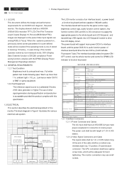
... (Display Power Management Signaling) standard. 1.2 GENERAL REQUIREMENTS 1.2.1 Test Condition Brightness level & contrast level max. The CPU connection shall have an IEC/CEE-22 type male power receptacle for TTL (N or P) Digital : H : 30kHz~81kHz V : 56Hz~76Hz Pixel clock 165MHz (Max) Video Input Analog ...panel , and transmitting LVDS signals into LCD flat panel module to AC Inverter. Full white pattern test mode following spec. 2 ACER X223W Go to mains power. Product Specification 1.1 SCOPE This document defines the design and performance requirements for an 20/22W inch ...
... (Display Power Management Signaling) standard. 1.2 GENERAL REQUIREMENTS 1.2.1 Test Condition Brightness level & contrast level max. The CPU connection shall have an IEC/CEE-22 type male power receptacle for TTL (N or P) Digital : H : 30kHz~81kHz V : 56Hz~76Hz Pixel clock 165MHz (Max) Video Input Analog ...panel , and transmitting LVDS signals into LCD flat panel module to AC Inverter. Full white pattern test mode following spec. 2 ACER X223W Go to mains power. Product Specification 1.1 SCOPE This document defines the design and performance requirements for an 20/22W inch ...
X223W LCD Service Guide
Page 4
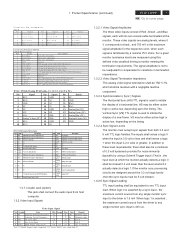
... TMDS link #0 channel#1 differentialpair 11 GND GNDfor no link share 20 NC NC 21 NC NC 22 GND Clock shield 23 RXC+ TMDS clock differentialpair 24 RXCC1 Analog Red C2 Analog Green TMDS clock ... the 3.3 volt logic family ,then the sync inputs must accept sync signals from host computer. 1.3.2 Video Input Signals Video Input Signal No. 1. Product Specification (continued) ACER X223W 3 Go to cover page C o n n e c to r P in A ssig n m e n t D SU B P in 1 S ig n a l R e d -V id e o P in 6 2 G re e n -V id e o 7 3 B lu e -V id e o 8 4 NC 9 5 D D C -G N D 10 ...
... TMDS link #0 channel#1 differentialpair 11 GND GNDfor no link share 20 NC NC 21 NC NC 22 GND Clock shield 23 RXC+ TMDS clock differentialpair 24 RXCC1 Analog Red C2 Analog Green TMDS clock ... the 3.3 volt logic family ,then the sync inputs must accept sync signals from host computer. 1.3.2 Video Input Signals Video Input Signal No. 1. Product Specification (continued) ACER X223W 3 Go to cover page C o n n e c to r P in A ssig n m e n t D SU B P in 1 S ig n a l R e d -V id e o P in 6 2 G re e n -V id e o 7 3 B lu e -V id e o 8 4 NC 9 5 D D C -G N D 10 ...
X223W LCD Service Guide
Page 7
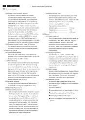
....This panel shall be approved for use DDC I2C bus to do update firmware. 1.4 PANEL ELECTRICAL 1.4.1 General Requirements The panel used as follows : For P20/22 W Series. ■Viewing distance is to be approximately 35-50cm ■Ambient illumination is restarted from the D-Sub connector, use in this test , the ambient... area , there shall be perceived as having ended when the illumination of light has reached 50% of the light guide that conforms to cover page 1. 6 ACER X223W Go to VESA DDC2Bi hardware requirements.
....This panel shall be approved for use DDC I2C bus to do update firmware. 1.4 PANEL ELECTRICAL 1.4.1 General Requirements The panel used as follows : For P20/22 W Series. ■Viewing distance is to be approximately 35-50cm ■Ambient illumination is restarted from the D-Sub connector, use in this test , the ambient... area , there shall be perceived as having ended when the illumination of light has reached 50% of the light guide that conforms to cover page 1. 6 ACER X223W Go to VESA DDC2Bi hardware requirements.
X223W LCD Service Guide
Page 23
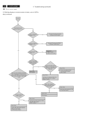
... failure 2) I305 is failure. 1) Printed wire between P304 and I305 LVDS signals. 2) I305 is High level. OK Check the D326 pin1 if voltage is short. 22 ACER X223W Go to 1.6V. OK OK Failure Point Check the I301 pin2 if voltage is 5V NG 1) FB301 is open. 2) C309, C310 is 1.8V NG...
... failure 2) I305 is failure. 1) Printed wire between P304 and I305 LVDS signals. 2) I305 is High level. OK Check the D326 pin1 if voltage is short. 22 ACER X223W Go to 1.6V. OK OK Failure Point Check the I301 pin2 if voltage is 5V NG 1) FB301 is open. 2) C309, C310 is 1.8V NG...
X223W LCD Service Guide
Page 37
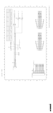
... LVA0M LVA0P LVA1M LVA1P LVA2M LVA2P LVACKM LVACKP LVA3M LVA3P VLCD VLCD 12 13 P304 32 31 30 29 28 27 26 25 24 23 22 21 20 19 18 17 16 15 14 13 12 11 10 9 8 7 6 5 4 3 2 1 CVILUX-CF25302D0R0 FOR THE DOWN SIDE A B C D E F G LED_A LED_G ADC2_IN ADC1_IN LED_A LED_G TP127... 0.498V 0.498V C386 0.1UF C388 0.1UF C389 0.1UF C390 0.1UF 1 2 3 4 5 6 7 8 9 LED_Blue LED_Amber KEY_ADC2 KEY_ADC1 P306 1 2 3 4 5 6 JWT-A2001WV2-06 10 11 12 13 PCB No. 6832190100P01 D E F G ACER X223W 36 Go to cover page
... LVA0M LVA0P LVA1M LVA1P LVA2M LVA2P LVACKM LVACKP LVA3M LVA3P VLCD VLCD 12 13 P304 32 31 30 29 28 27 26 25 24 23 22 21 20 19 18 17 16 15 14 13 12 11 10 9 8 7 6 5 4 3 2 1 CVILUX-CF25302D0R0 FOR THE DOWN SIDE A B C D E F G LED_A LED_G ADC2_IN ADC1_IN LED_A LED_G TP127... 0.498V 0.498V C386 0.1UF C388 0.1UF C389 0.1UF C390 0.1UF 1 2 3 4 5 6 7 8 9 LED_Blue LED_Amber KEY_ADC2 KEY_ADC1 P306 1 2 3 4 5 6 JWT-A2001WV2-06 10 11 12 13 PCB No. 6832190100P01 D E F G ACER X223W 36 Go to cover page
