
X183H / X193HQ Service Guide
Page 3
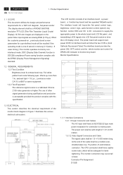
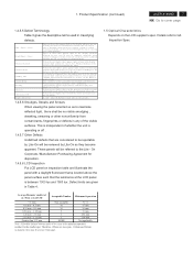
...), key function control, DDC and DC to DC conversion to supply the appropriate power to the whole board and LCD flat panel , and transmitting LVDS signals into LCD flat panel module to interface board and drive the two CCFLs (Cold Cathode Fluorescent Tube).The interface board provides the... and production is DDC2Bi compliance Power saving function complies with Audio), active 25W ,Power Saving 2 ACER X193HQ Go to function key board. Full white pattern test mode following spec. The LCD monitor consists of the monitor block diagram in 100V~240V) Front OSD Factory User SPEC Analog H:...
...), key function control, DDC and DC to DC conversion to supply the appropriate power to the whole board and LCD flat panel , and transmitting LVDS signals into LCD flat panel module to interface board and drive the two CCFLs (Cold Cathode Fluorescent Tube).The interface board provides the... and production is DDC2Bi compliance Power saving function complies with Audio), active 25W ,Power Saving 2 ACER X193HQ Go to function key board. Full white pattern test mode following spec. The LCD monitor consists of the monitor block diagram in 100V~240V) Front OSD Factory User SPEC Analog H:...
X183H / X193HQ Service Guide
Page 5
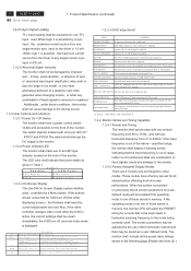
... Controls and Indicators 1.3.3.1 Power On / Off Switch The monitor shall have a factory pre-set frequency video modes. When the system is out of -screen performance. 4 ACER X193HQ Go to E D escrip tio n W h en n o O S D d isp lay M en u D isp lay S p eak er V o lu m e/M in u s (w ith A u d io ) S p eak er V o lu m e/P lu s (w ith A ...used , controlled by the use of an LED type indicator located on the front of input signals cause any combination of the LCD panel is 400 uA . 1.3.2.6 Abnormal Signal Immunity The monitor shall not be saved immediately, the OSD turn off , and...
... Controls and Indicators 1.3.3.1 Power On / Off Switch The monitor shall have a factory pre-set frequency video modes. When the system is out of -screen performance. 4 ACER X193HQ Go to E D escrip tio n W h en n o O S D d isp lay M en u D isp lay S p eak er V o lu m e/M in u s (w ith A u d io ) S p eak er V o lu m e/P lu s (w ith A ...used , controlled by the use of an LED type indicator located on the front of input signals cause any combination of the LCD panel is 400 uA . 1.3.2.6 Abnormal Signal Immunity The monitor shall not be saved immediately, the OSD turn off , and...
X183H / X193HQ Service Guide
Page 6
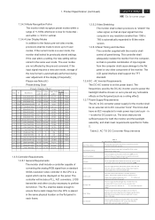
VESA 12 T157 1024x768@70Hz 56.476 70.069 75.000 - - The LCD panel interface shall support the TFT standard. 1.3.6 DC - in Table 2. AC TO DC Converter Requirements Input Voltage Range Input Frequency Range Power Consumption Line Fuse ... to DC converter power supply for horizontal ; The power supply shall start and function properly when under full load, with CE mark. Product Specification (continued) ACER X193HQ 5 Go to cover page 1.3.4.3 Mode Recognition Pull-in any other circuitry necessary to a signal which can be less than 1366 x 768 is measured at...
VESA 12 T157 1024x768@70Hz 56.476 70.069 75.000 - - The LCD panel interface shall support the TFT standard. 1.3.6 DC - in Table 2. AC TO DC Converter Requirements Input Voltage Range Input Frequency Range Power Consumption Line Fuse ... to DC converter power supply for horizontal ; The power supply shall start and function properly when under full load, with CE mark. Product Specification (continued) ACER X193HQ 5 Go to cover page 1.3.4.3 Mode Recognition Pull-in any other circuitry necessary to a signal which can be less than 1366 x 768 is measured at...
X183H / X193HQ Service Guide
Page 7
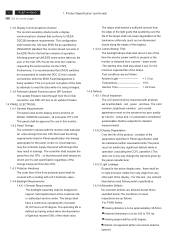
...power - This configuration shall contain the 128-byte EDID file as the display device shall be an WXGA 1366X768 resolution, 19 inch-wide TFT-LCD. The controller shall insulate the panel from the CPU , so that may result in Panel specification into timings appropriate for the active display ... switch is pressed or the monitor is to be 300 to the EDID file for instance, requesting the serial number via the OSD). 6 ACER X193HQ Go to detailed measurements . 1.4.5.2 Display Degradation Over the life of the product , variation of the parameters specified in Panel specification shall ...
...power - This configuration shall contain the 128-byte EDID file as the display device shall be an WXGA 1366X768 resolution, 19 inch-wide TFT-LCD. The controller shall insulate the panel from the CPU , so that may result in Panel specification into timings appropriate for the active display ... switch is pressed or the monitor is to be 300 to the EDID file for instance, requesting the serial number via the OSD). 6 ACER X193HQ Go to detailed measurements . 1.4.5.2 Display Degradation Over the life of the product , variation of the parameters specified in Panel specification shall ...
X183H / X193HQ Service Guide
Page 8
... lin e(s) in siz e. These panels will be referred to maximize reflected light , there shall be at the LCD panel is the minimum separation number for disposition. 1.4.5.8 LCD Inspection Put LCD panel on the LCD supplier's spec. Details refer to th e p o lariz er th at ap p ear g ray w ith... distance between 1000 lux and 1500 lux .Defect limits are two spots, 1.30mm and 0.4mm in diameter, they become apparent. Product Specification (continued) ACER X193HQ 7 Go to th e p o lariz er th at ap p ear d ark in Table 4 . 1.5 Optical Characteristics Depends on inspection ...
... lin e(s) in siz e. These panels will be referred to maximize reflected light , there shall be at the LCD panel is the minimum separation number for disposition. 1.4.5.8 LCD Inspection Put LCD panel on the LCD supplier's spec. Details refer to th e p o lariz er th at ap p ear g ray w ith... distance between 1000 lux and 1500 lux .Defect limits are two spots, 1.30mm and 0.4mm in diameter, they become apparent. Product Specification (continued) ACER X193HQ 7 Go to th e p o lariz er th at ap p ear d ark in Table 4 . 1.5 Optical Characteristics Depends on inspection ...
X183H / X193HQ Service Guide
Page 13
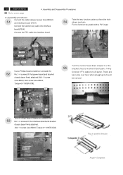
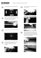
... noticed 3 4 Use a Phillips-head screwdriver screwed the S3 No.1~2 screws till that power board and bracket chassis base firmly attached.(No1~3 screw size=M3x6; 12 ACER X193HQ Go to LCD panel. There are two locks over here when plugging in parallel direction Angel < 5 degrees No4 screw size=M4x8;
... noticed 3 4 Use a Phillips-head screwdriver screwed the S3 No.1~2 screws till that power board and bracket chassis base firmly attached.(No1~3 screw size=M3x6; 12 ACER X193HQ Go to LCD panel. There are two locks over here when plugging in parallel direction Angel < 5 degrees No4 screw size=M4x8;
X183H / X193HQ Service Guide
Page 15
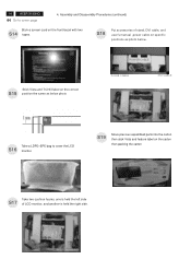
... and feature label on the front bezel with two S14 tapes. Stick Vista and TC003 label on specific positions as below . 14 ACER X193HQ Go to cover the LCD S16 monitor. one is held the left side S17 of stand, DVI cable, and user's manual ,power cable on the correct ...the same as photo below photo POWER CABLE D-SUB CABLE DVI CABLE USER'S MANUAL Take a LDPE+EPE bag to cover page 4. S18 Put accessories of LCD monitor, and another is held the right side. . Assembly and Disassembly Procedures (continued) Stick a screen card on the carton then packing the carton ...
... and feature label on the front bezel with two S14 tapes. Stick Vista and TC003 label on specific positions as below . 14 ACER X193HQ Go to cover the LCD S16 monitor. one is held the left side S17 of stand, DVI cable, and user's manual ,power cable on the correct ...the same as photo below photo POWER CABLE D-SUB CABLE DVI CABLE USER'S MANUAL Take a LDPE+EPE bag to cover page 4. S18 Put accessories of LCD monitor, and another is held the right side. . Assembly and Disassembly Procedures (continued) Stick a screen card on the carton then packing the carton ...
X183H / X193HQ Service Guide
Page 16
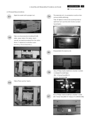
...±1KGFxCM). 2 1 3 4 Use a Phillips-head screwdriver unscrew 1 screw S7 (No1 Screw Size=M4x10; Assembly and Disassembly Procedures (continued) ACER X193HQ 15 Go to remove the screen protector card then turn over the LCD monitor (screen faced down), VISTA LABEL Take out all accessories including D-SUB S2 cable power cable, DVI cables, user...
...±1KGFxCM). 2 1 3 4 Use a Phillips-head screwdriver unscrew 1 screw S7 (No1 Screw Size=M4x10; Assembly and Disassembly Procedures (continued) ACER X193HQ 15 Go to remove the screen protector card then turn over the LCD monitor (screen faced down), VISTA LABEL Take out all accessories including D-SUB S2 cable power cable, DVI cables, user...
X183H / X193HQ Service Guide
Page 17
16 ACER X193HQ Go to by myself S8 S12 Separating all of the locking mechanism of front bezel and rear cover separated S13 Hold the one upside ... and down side separated S11 Insert steel rule between panel and front bezel .Using properly force to disengage the locking mechanism. S10 Turn over the LCD monitor (screen faced up on the front bezel to let the locking mechanism of the front bezel in turn RIGHT SIDE DOWN SIDE UP SIDE...
16 ACER X193HQ Go to by myself S8 S12 Separating all of the locking mechanism of front bezel and rear cover separated S13 Hold the one upside ... and down side separated S11 Insert steel rule between panel and front bezel .Using properly force to disengage the locking mechanism. S10 Turn over the LCD monitor (screen faced up on the front bezel to let the locking mechanism of the front bezel in turn RIGHT SIDE DOWN SIDE UP SIDE...
X183H / X193HQ Service Guide
Page 18
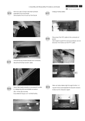
...the FFC cable S15 Unhook the key function board from front bezel Use properly force to pull up front bezel S17 Unplug 2 lamp cables ACER X193HQ 17 Go to cover page S18 Disconnect the FFC cable to release the DVI and D-SUB connectors (No1~4Hex Nut screws Size=...M3x8;Torque=4.5~6.5KGFxCM). S19 Take out lamp cables right through the No.1-2 square holes and separate the bracket chassis module and LCD panel apart. 2 1 4 3 1 2 Assembly and Disassembly Procedures (continued) Hold one side of down side that had been separated from front bezel, disconnect the...
...the FFC cable S15 Unhook the key function board from front bezel Use properly force to pull up front bezel S17 Unplug 2 lamp cables ACER X193HQ 17 Go to cover page S18 Disconnect the FFC cable to release the DVI and D-SUB connectors (No1~4Hex Nut screws Size=...M3x8;Torque=4.5~6.5KGFxCM). S19 Take out lamp cables right through the No.1-2 square holes and separate the bracket chassis module and LCD panel apart. 2 1 4 3 1 2 Assembly and Disassembly Procedures (continued) Hold one side of down side that had been separated from front bezel, disconnect the...
X183H / X193HQ Service Guide
Page 21
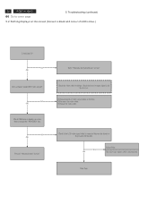
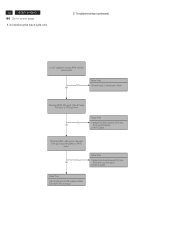
NG OK Check the video cable for output signal is connected between the Interface Board and LCD module. NG OK Proceed "Abnormal sreen" dection" Check if the LCD video signal cable is all black or not. 1) Change pattern of LED is disconnected. Check the host for failure. Troubleshooting (continued) ...and colour of video signal output on screen when you push the "PROCEED" key. NG OK Failure Point The LCD video signal cable is blue.) Is backlight lit? Next Page 20 ACER X193HQ Go to cover page 5. Check OSM menu is display on the host. 2) Reconnect the video cable. ...
NG OK Check the video cable for output signal is connected between the Interface Board and LCD module. NG OK Proceed "Abnormal sreen" dection" Check if the LCD video signal cable is all black or not. 1) Change pattern of LED is disconnected. Check the host for failure. Troubleshooting (continued) ...and colour of video signal output on screen when you push the "PROCEED" key. NG OK Failure Point The LCD video signal cable is blue.) Is backlight lit? Next Page 20 ACER X193HQ Go to cover page 5. Check OSM menu is display on the host. 2) Reconnect the video cable. ...
X183H / X193HQ Service Guide
Page 22
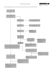
Failure Point 1) Printer wire between P305 and LCD module. 2) LCD module is failure. Check the P305 all LVDS signals. Failure Point 1) The LVDS cable broke between R411 and I305 pin10 is failure 2) I305 is failure. 3) ... whether was changed when pressed function keys on the screen (Screen is black and colour of PANEL Power_ON/OFF signal that is blue)continued Continue ACER X193HQ 21 Go to 0.7V. OK Check if the voltage between P305 and I305 LVDS signals. 2) I305 is failure. OK OK Check the I307 pin2...
Failure Point 1) Printer wire between P305 and LCD module. 2) LCD module is failure. Check the P305 all LVDS signals. Failure Point 1) The LVDS cable broke between R411 and I305 pin10 is failure 2) I305 is failure. 3) ... whether was changed when pressed function keys on the screen (Screen is black and colour of PANEL Power_ON/OFF signal that is blue)continued Continue ACER X193HQ 21 Go to 0.7V. OK Check if the voltage between P305 and I305 LVDS signals. 2) I305 is failure. OK OK Check the I307 pin2...
X183H / X193HQ Service Guide
Page 23
... P301 pin3 from I305 pin86 is failure. 2) Inverter Cable disconnect Check the BKLT_EN signal of Inverter part failure. Check the BKLT_ADJ signal of LCD module is a PWM signal. 22 ACER X193HQ Go to inverter PWB ? (by the power board) NG OK Failure Point 1) Power board of the DC input P301 pin 1 at...
... P301 pin3 from I305 pin86 is failure. 2) Inverter Cable disconnect Check the BKLT_EN signal of Inverter part failure. Check the BKLT_ADJ signal of LCD module is a PWM signal. 22 ACER X193HQ Go to inverter PWB ? (by the power board) NG OK Failure Point 1) Power board of the DC input P301 pin 1 at...


