

Power SC Service Guide
Page 11
...interface ! Software shutdown for ACPI compliant) ! On-board serial port- AcerPower Sc Features Performance ! Built-in -line memory module (DIMM) sockets that accept...! Slim, smooth and stylish design Chapter 1 3 On-board PCI master enhanced local bus IDE ! Power management function (Support for Windows 98se/ME/2K/XP ! On-board parallel port- On-board Audio ...High-speed fax/data PCI modem Human-centric design and ergonomics ! Dual in SiS900 10/100BASE-T Ethernet controller (RJ-45 connector) ! EPP, ECP, and IEEE 1284 ! Low Pin Count (LPC) I/F ! 3 PCI slots + 2 DIMM slots...
...interface ! Software shutdown for ACPI compliant) ! On-board serial port- AcerPower Sc Features Performance ! Built-in -line memory module (DIMM) sockets that accept...! Slim, smooth and stylish design Chapter 1 3 On-board PCI master enhanced local bus IDE ! Power management function (Support for Windows 98se/ME/2K/XP ! On-board parallel port- On-board Audio ...High-speed fax/data PCI modem Human-centric design and ergonomics ! Dual in SiS900 10/100BASE-T Ethernet controller (RJ-45 connector) ! EPP, ECP, and IEEE 1284 ! Low Pin Count (LPC) I/F ! 3 PCI slots + 2 DIMM slots...
Power SC Service Guide
Page 15
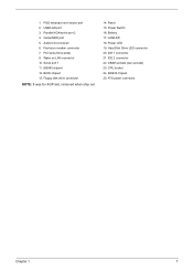
... for AGP slot, removed when ship out 14. LAN/LED 18. Wake on LAN connector 10. Hard Disk Drive LED connector 20. SiS630 chipset 25. SiS950 chipset 12. Power Switch 16. DIMM sockets (two sockets) 23. Reset 15. ATX power connector Chapter 1 7 PS/2 keyboard and mouse port 2. Battery 17. 1. USB/LAN port 3. Fax/voice modem...
... for AGP slot, removed when ship out 14. LAN/LED 18. Wake on LAN connector 10. Hard Disk Drive LED connector 20. SiS630 chipset 25. SiS950 chipset 12. Power Switch 16. DIMM sockets (two sockets) 23. Reset 15. ATX power connector Chapter 1 7 PS/2 keyboard and mouse port 2. Battery 17. 1. USB/LAN port 3. Fax/voice modem...

Power SC Service Guide
Page 16
Hard Disk Drive LED connector 4. ROM 6. Optional USB ports 7. Wake on LAN connector 10. CPU socket 13. ATX power connector 14. Floppy disk drive connector 8. PS/2 keyboard and mouse port 8 Chapter 1 IDE 1 connector 2. Audio-in connector 16. PCI sockets (three slots) 17. DIMM sockets 12. SiS950 chipset 9. RTC Battery 5. Fax voice modem connector 11. Audio/CD connector 15. IDE 2 connector 3. AcerPower Sc Main Board Layout 1.
Hard Disk Drive LED connector 4. ROM 6. Optional USB ports 7. Wake on LAN connector 10. CPU socket 13. ATX power connector 14. Floppy disk drive connector 8. PS/2 keyboard and mouse port 8 Chapter 1 IDE 1 connector 2. Audio-in connector 16. PCI sockets (three slots) 17. DIMM sockets 12. SiS950 chipset 9. RTC Battery 5. Fax voice modem connector 11. Audio/CD connector 15. IDE 2 connector 3. AcerPower Sc Main Board Layout 1.
Power SC Service Guide
Page 78
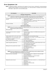
... cursor only; Processor test failed. 1. System board Incorrect memory size shown or repeated during POST. 1. Diskette drive power 3. Its reading should be +12Vdc. 3. See "Index of processor fan connector. system does not work . 1. System works but power supply fan runs. 1. See "Undetermined Problems" System hangs after system boot. 1. Error Symptoms List NOTE: To...
... cursor only; Processor test failed. 1. System board Incorrect memory size shown or repeated during POST. 1. Diskette drive power 3. Its reading should be +12Vdc. 3. See "Index of processor fan connector. system does not work . 1. System works but power supply fan runs. 1. See "Undetermined Problems" System hangs after system boot. 1. Error Symptoms List NOTE: To...
Power SC Service Guide
Page 79
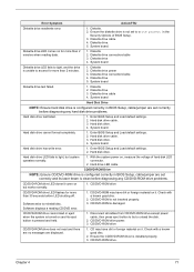
... Hard disk drive. CD/DVD-ROM may have dirt or foreign material on it . Disconnect all cables from CD/DVD-ROM drive except power cable, then press eject button to try to reinstall disc. Ensure the CD/DVD-ROM driver is configured correctly in BIOS Setup, cable... NOTE: Ensure CD/DVD-ROM drive is configured correctly in the Security Options of hard disk LED connector. 2. Software displays a reading CD/DVD error. 1. Diskette drive connection/cable 3. Diskette 2. CD/DVD-ROM drive power. 3. Hard disk drive cannot format completely. 1. Check with a known good disc. 2. System ...
... Hard disk drive. CD/DVD-ROM may have dirt or foreign material on it . Disconnect all cables from CD/DVD-ROM drive except power cable, then press eject button to try to reinstall disc. Ensure the CD/DVD-ROM driver is configured correctly in BIOS Setup, cable... NOTE: Ensure CD/DVD-ROM drive is configured correctly in the Security Options of hard disk LED connector. 2. Software displays a reading CD/DVD error. 1. Diskette drive connection/cable 3. Diskette 2. CD/DVD-ROM drive power. 3. Hard disk drive cannot format completely. 1. Check with a known good disc. 2. System ...
Power SC Service Guide
Page 81
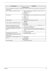
... the same as the setting in BIOS Setup of the machine, just above the connector for the printer. Ensure the printer driver is not running. 1. Refer to OFF. 2. System board. Power switch cable assembly. Reload software from Windows98 Start menu does not turn off the system...Parallel/Serial Ports Execute "Load BIOS Default Settings" in BIOS Setup to the service manual for the power cable) is not set to Suspend. 2. Printer problems. 1. Keyboard Power Supply Pressing power switch does not turn off the system). 1. Printer cable. 4. Refer to confirm ports presence ...
... the same as the setting in BIOS Setup of the machine, just above the connector for the printer. Ensure the printer driver is not running. 1. Refer to OFF. 2. System board. Power switch cable assembly. Reload software from Windows98 Start menu does not turn off the system...Parallel/Serial Ports Execute "Load BIOS Default Settings" in BIOS Setup to the service manual for the power cable) is not set to Suspend. 2. Printer problems. 1. Keyboard Power Supply Pressing power switch does not turn off the system). 1. Printer cable. 4. Refer to confirm ports presence ...

Power SC Service Guide
Page 84
Check all cables and connectors for proper installation. 9. Check all adapter card jumper positions. 7. CD/DVD-ROM drive ! DIMM ! Power on page 68 . Repeat steps 2 through 5 until you find the failing device or adapter. 76 Chapter 4 If the voltages are correct, remove or disconnect...problem, continue with the following checks, one by one at a time: 10. Load default settings in "or "Error Symptoms List" on page 70. Non-Acer devices ! System board 11. If you did not receive any messages, see if the symptom is present, go to "POST Error Messages List" on the...
Check all cables and connectors for proper installation. 9. Check all adapter card jumper positions. 7. CD/DVD-ROM drive ! DIMM ! Power on page 68 . Repeat steps 2 through 5 until you find the failing device or adapter. 76 Chapter 4 If the voltages are correct, remove or disconnect...problem, continue with the following checks, one by one at a time: 10. Load default settings in "or "Error Symptoms List" on page 70. Non-Acer devices ! System board 11. If you did not receive any messages, see if the symptom is present, go to "POST Error Messages List" on the...

Power SC Service Guide
Page 86
...100 100 133 133 66 Chapter 5 Description CN1 PS/2 CN2 USB/LAN CN3 ATX power connector CN4 COM port CN5 Parallel/VGA/serial port 2 CN7 IDE2 CN8 IDE1 CN9 GAME/MIDI CN11 Audio CD connector CN12 Floppy Disk Drive CN13 Hard Disk Drive LED CN16 Fax voice modem CN18 WAKE ON... LAN CN19 36-pin USB/AUDIO connector CN20 RF connector CN21 Slim CD-ROM connector JP1 1/2: Disable on board codec 2/3: Enable on board codec JP2 PWR LED JP3 1/2, 4/5: 4M flash ROM 2/3, 5/6: 2M flash ROM JP4 ...
...100 100 133 133 66 Chapter 5 Description CN1 PS/2 CN2 USB/LAN CN3 ATX power connector CN4 COM port CN5 Parallel/VGA/serial port 2 CN7 IDE2 CN8 IDE1 CN9 GAME/MIDI CN11 Audio CD connector CN12 Floppy Disk Drive CN13 Hard Disk Drive LED CN16 Fax voice modem CN18 WAKE ON... LAN CN19 36-pin USB/AUDIO connector CN20 RF connector CN21 Slim CD-ROM connector JP1 1/2: Disable on board codec 2/3: Enable on board codec JP2 PWR LED JP3 1/2, 4/5: 4M flash ROM 2/3, 5/6: 2M flash ROM JP4 ...

Power SC Service Guide
Page 88
Connector Description Connector No. Description CN1 PS/2 connectors CN2 USB/LAN connectors CN3 ATX power connector CN5 Printer/VGA/COM2 connectors CN7 IDE2 connector CN8 IDE1 connector CN9 GAME/MIDI port CN10 12-pin AC'97 connector CN11 Audio CD connector CN12 Floppy Disk Drive connector CN13 Hard Disk Drive LED connector CN16 Fax voice modem connector CN18 Wake-on LAN connector CN22 Optional USB ports...
Connector Description Connector No. Description CN1 PS/2 connectors CN2 USB/LAN connectors CN3 ATX power connector CN5 Printer/VGA/COM2 connectors CN7 IDE2 connector CN8 IDE1 connector CN9 GAME/MIDI port CN10 12-pin AC'97 connector CN11 Audio CD connector CN12 Floppy Disk Drive connector CN13 Hard Disk Drive LED connector CN16 Fax voice modem connector CN18 Wake-on LAN connector CN22 Optional USB ports...

Power SC Service Guide
Page 89
... 5 Connector Description Connector No. Description CN1 PS/2 connectors CN2 USB/LAN connectors CN3 ATX power connector CN5 Printer/VGA/COM2 connectors CN7 IDE2 connector CN8 IDE1 connector CN9 GAME/MIDI port CN10 12-pin AC'97 connector CN11 Audio CD connector CN12 Floppy Disk Drive connector CN13 Hard Disk Drive LED connector CN16 Fax voice modem connector CN18 Wake-on LAN connector CN20 RF connector CN21...
... 5 Connector Description Connector No. Description CN1 PS/2 connectors CN2 USB/LAN connectors CN3 ATX power connector CN5 Printer/VGA/COM2 connectors CN7 IDE2 connector CN8 IDE1 connector CN9 GAME/MIDI port CN10 12-pin AC'97 connector CN11 Audio CD connector CN12 Floppy Disk Drive connector CN13 Hard Disk Drive LED connector CN16 Fax voice modem connector CN18 Wake-on LAN connector CN20 RF connector CN21...
Power SC Service Guide
Page 114
...ACPI 21 Advanced Options 43 PnP/PCI 45 Assignment Map 17 ATX Power connector 78 Audio controller 15 Audio CD connector 78 Audio Interface 15 B Basic level 24 BIOS Setup 23 Entering... Cache Memory 14 Index Index scheme 14 size 14 speed 14 type 14 voltage 14 CD-ROM connector 78 Chipset Settings 46 Delay Transaction 47 ICH Audio Controller 47 ICH Modem Controller 47 Memory Stable Register...value 47 Spread Spectrum 47 System Utilities 46 Chipsets 19 CMOS Setup 23 Compatibility Test 93 Connector Description 78, 80 Connectors 77, 79 controllers 19 audio 15 serial port 16 video 14 CPR 45 CPU Board ...
...ACPI 21 Advanced Options 43 PnP/PCI 45 Assignment Map 17 ATX Power connector 78 Audio controller 15 Audio CD connector 78 Audio Interface 15 B Basic level 24 BIOS Setup 23 Entering... Cache Memory 14 Index Index scheme 14 size 14 speed 14 type 14 voltage 14 CD-ROM connector 78 Chipset Settings 46 Delay Transaction 47 ICH Audio Controller 47 ICH Modem Controller 47 Memory Stable Register...value 47 Spread Spectrum 47 System Utilities 46 Chipsets 19 CMOS Setup 23 Compatibility Test 93 Connector Description 78, 80 Connectors 77, 79 controllers 19 audio 15 serial port 16 video 14 CPR 45 CPU Board ...

Power SC Service Guide
Page 116
... port 1 34 serial port 2 34 USB Host Controller 35 USB Legacy Mode 35 Online Support Information 103 Overview 1 P Parallel Port 16 Parallel/VGA/serial port 2 connector 78 Password bypassing 42 changing 42 removing 42 setting 41 PCI INTx# 17 PCI Slot IRQ 17 PnP PCI Options Graphics Aperture Size 45 IRQ... 36 system wake-up event 36 Power-On Self-Test (POST) 64 Product Information 28 BIOS Release Date 29 main board ID 29 main board S/N 29 product name 29 SMBIOS version 29 System BIOS ID 29 system BIOS version 29 system serial number 29 PS/2 connector 78 PWR switch jumper 78 R Rear...
... port 1 34 serial port 2 34 USB Host Controller 35 USB Legacy Mode 35 Online Support Information 103 Overview 1 P Parallel Port 16 Parallel/VGA/serial port 2 connector 78 Password bypassing 42 changing 42 removing 42 setting 41 PCI INTx# 17 PCI Slot IRQ 17 PnP PCI Options Graphics Aperture Size 45 IRQ... 36 system wake-up event 36 Power-On Self-Test (POST) 64 Product Information 28 BIOS Release Date 29 main board ID 29 main board S/N 29 product name 29 SMBIOS version 29 System BIOS ID 29 system BIOS version 29 system serial number 29 PS/2 connector 78 PWR switch jumper 78 R Rear...
Power SC Service Guide
Page 117
... 38 Date 39 Disk Drives 30 Exiting Setup 49 108 Load Default Settings 47 Memory/Cache Options 43 Onboard Peripherals 33 PnP/PCI Options 45 Power Management 36 Product Information 28 System Security 40 Time 39 T Temperature 19 Test Compatible Components 93 Time 39 To 24 Troubleshooting 63 U UART ...16 Undetermined Problems 76 Universal HCI 17 USB Port 17 USB/AUDIO connector 78 USB/LAN connector 78 V Vibration 19 video controller 14 Video controller 14 Video Memory 14 configuration 14 package 14 size 14 speed 14 type 14 voltage...
... 38 Date 39 Disk Drives 30 Exiting Setup 49 108 Load Default Settings 47 Memory/Cache Options 43 Onboard Peripherals 33 PnP/PCI Options 45 Power Management 36 Product Information 28 System Security 40 Time 39 T Temperature 19 Test Compatible Components 93 Time 39 To 24 Troubleshooting 63 U UART ...16 Undetermined Problems 76 Universal HCI 17 USB Port 17 USB/AUDIO connector 78 USB/LAN connector 78 V Vibration 19 video controller 14 Video controller 14 Video Memory 14 configuration 14 package 14 size 14 speed 14 type 14 voltage...
Power Sc User's Guide
Page 49
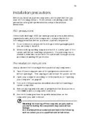
... connected to it before you install a system component: 1 2 Do not remove a component from the power outlets. Warning! 39 Installation precautions Before you install any system component, we recommend that block access to the DIMM sockets or component connector. See the following sections. Do not attempt the procedures described in the following before...
... connected to it before you install a system component: 1 2 Do not remove a component from the power outlets. Warning! 39 Installation precautions Before you install any system component, we recommend that block access to the DIMM sockets or component connector. See the following sections. Do not attempt the procedures described in the following before...

Power Sc User's Guide
Page 56
... CN21 CN22 CN23 JP1 Description PS/2 connectors USB/LAN connectors ATX power connector 4 Upgrading your computer Printer/VGA/COM2 connectors IDE2 connector IDE1 connector Game/MIDI port 12-pin AC'97 connector Audio CD connector FDD connector HDD LED connector Fax voice modem connector Wake-on LAN c onnector RF connector Slim CD-ROM connector Optional USB ports Audio-in connector 1-2: Disable onboard Codec 2-3: Enable onboard...
... CN21 CN22 CN23 JP1 Description PS/2 connectors USB/LAN connectors ATX power connector 4 Upgrading your computer Printer/VGA/COM2 connectors IDE2 connector IDE1 connector Game/MIDI port 12-pin AC'97 connector Audio CD connector FDD connector HDD LED connector Fax voice modem connector Wake-on LAN c onnector RF connector Slim CD-ROM connector Optional USB ports Audio-in connector 1-2: Disable onboard Codec 2-3: Enable onboard...

Power Sc User's Guide
Page 57
47 Connector JP7 JP9 Description Power switch connector 1-2: set CN21 as slave 2-3: set CN21 as Master CPU frequency table S4 0 0 0 0 0 0 0 1 S3 0 0 0 0 1 1 1 0 S2 0 0 1 1 0 1 1 0 S1 0 1 0 1 1 0 1 0 CPU 66 100 150 133 100 100 133 66 SDRAM 100 100 100 100 133 150 133 66
47 Connector JP7 JP9 Description Power switch connector 1-2: set CN21 as slave 2-3: set CN21 as Master CPU frequency table S4 0 0 0 0 0 0 0 1 S3 0 0 0 0 1 1 1 0 S2 0 0 1 1 0 1 1 0 S1 0 1 0 1 1 0 1 0 CPU 66 100 150 133 100 100 133 66 SDRAM 100 100 100 100 133 150 133 66

Power Sc User's Guide
Page 66
56 c 4 Upgrading your computer Connect the disk drive cables and power cables. Note: Make sure that the other ends of the floppy disk drive cables are connected to their corresponding connectors on the system board. 7 Reinstall the housing cover as instructed on page 43.
56 c 4 Upgrading your computer Connect the disk drive cables and power cables. Note: Make sure that the other ends of the floppy disk drive cables are connected to their corresponding connectors on the system board. 7 Reinstall the housing cover as instructed on page 43.


