
Power SC Service Guide
Page 7
... Panel 4 Rear Panel 5 AcerPower Sx Main Board Layout 6 AcerPower Sc Main Board Layout 8 Keyboard 9 Cursor keys 9 Lock keys 9 Windows keys 10 Hardware Specifications and Configurations 11 Power Management Function (ACPI support function 21 Chapter 2 System Utilities 23 Entering Setup 24 System Information 26 Product Information 28 Disk Drives 30 IDE Primary/Secondary Channel Master/Slave 31 Onboard Peripherals 33 Power Management 36 Boot Options 38 Date and Time 39 System Security 40 Setting a Password 41 Changing or Removing the Password 42 Bypassing the Password...
... Panel 4 Rear Panel 5 AcerPower Sx Main Board Layout 6 AcerPower Sc Main Board Layout 8 Keyboard 9 Cursor keys 9 Lock keys 9 Windows keys 10 Hardware Specifications and Configurations 11 Power Management Function (ACPI support function 21 Chapter 2 System Utilities 23 Entering Setup 24 System Information 26 Product Information 28 Disk Drives 30 IDE Primary/Secondary Channel Master/Slave 31 Onboard Peripherals 33 Power Management 36 Boot Options 38 Date and Time 39 System Security 40 Setting a Password 41 Changing or Removing the Password 42 Bypassing the Password...
Power SC Service Guide
Page 10
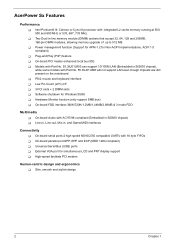
... mainboard. ! Low Pin Count (LPC) I/F ! 3 PCI slots + 2 DIMM slots ! Plug-and Play (PnP) feature ! External VGA port for Windows 95/98 ! Universal Serial Bus (USB) ports ! AcerPower Sx Features Performance ! Hardware Monitor function (only support SMB bus) ! On-board parallel port-SPP, EPP and ECP (IEEE 1284 compliant) ! PS/2 mouse and keyboard interface ! Intel Pentium® III, Celeron or Cyrix III processor with 16 byte FIFOs ! Power management function (Support for APM-1.2 for...
... mainboard. ! Low Pin Count (LPC) I/F ! 3 PCI slots + 2 DIMM slots ! Plug-and Play (PnP) feature ! External VGA port for Windows 95/98 ! Universal Serial Bus (USB) ports ! AcerPower Sx Features Performance ! Hardware Monitor function (only support SMB bus) ! On-board parallel port-SPP, EPP and ECP (IEEE 1284 compliant) ! PS/2 mouse and keyboard interface ! Intel Pentium® III, Celeron or Cyrix III processor with 16 byte FIFOs ! Power management function (Support for APM-1.2 for...
Power SC Service Guide
Page 19
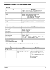
... booting to enter BIOS Setup Utility. BIOS Item BIOS code programmer BIOS version BIOS ROM type BIOS ROM size BIOS ROM package Support protocol Boot from 1.2 to Enabled.) Processor voltage can be detected by the system without setting any jumper. BIOS Hotkey List Hotkey ++ F8 Function Enter BIOS Setup Utility Enable hidden page of BIOS Setup Utility Description Press while the system is set to 1.4 GHz and above Celeron 850/950 MHz , 1.1/1.2 GHz 0 MHz (If Stop CPU Clock in Sleep State in BIOS Setup Utility main menu screen, the Advanced Options menu...
... booting to enter BIOS Setup Utility. BIOS Item BIOS code programmer BIOS version BIOS ROM type BIOS ROM size BIOS ROM package Support protocol Boot from 1.2 to Enabled.) Processor voltage can be detected by the system without setting any jumper. BIOS Hotkey List Hotkey ++ F8 Function Enter BIOS Setup Utility Enable hidden page of BIOS Setup Utility Description Press while the system is set to 1.4 GHz and above Celeron 850/950 MHz , 1.1/1.2 GHz 0 MHz (If Stop CPU Clock in Sleep State in BIOS Setup Utility main menu screen, the Advanced Options menu...
Power SC Service Guide
Page 35
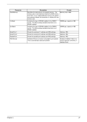
... there is automatically detected by BIOS during the POST. Shows the serial port 1 address and IRQ settings. Indicates if there is a mouse detected; Format Memory size in MB DIMM type, capacity in MB DIMM type, capacity in MB Address, IRQ Address, IRQ Address, IRQ Displays Installed if there is a mouse connected to display the new memory size. If you install additional memory, the system automatically adjusts this...
... there is automatically detected by BIOS during the POST. Shows the serial port 1 address and IRQ settings. Indicates if there is a mouse detected; Format Memory size in MB DIMM type, capacity in MB DIMM type, capacity in MB Address, IRQ Address, IRQ Address, IRQ Displays Installed if there is a mouse connected to display the new memory size. If you install additional memory, the system automatically adjusts this...
Power SC Service Guide
Page 40
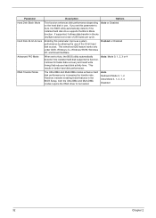
... hard disk access. Options Auto or Disabled Enabled or Disabled Auto, Mode 0, 1, 2, 3 or 4 Auto Multiword Mode 0, 1, 2 Ultra Mode 0, 1, 2, 3, 4 Disabled 32 Chapter 2 Enabling this parameter to Auto, the BIOS utility automatically detects if the installed hard disk drive supports the Block Mode function. When set this parameter improves system performance by increasing the transfer rate. The Ultra DMA and Multi-DMA modes enhance hard disk performance by allowing the use . Parameter Hard Disk Block Mode Hard Disk 32-bit Access Advanced PIO Mode...
... hard disk access. Options Auto or Disabled Enabled or Disabled Auto, Mode 0, 1, 2, 3 or 4 Auto Multiword Mode 0, 1, 2 Ultra Mode 0, 1, 2, 3, 4 Disabled 32 Chapter 2 Enabling this parameter to Auto, the BIOS utility automatically detects if the installed hard disk drive supports the Block Mode function. When set this parameter improves system performance by increasing the transfer rate. The Ultra DMA and Multi-DMA modes enhance hard disk performance by allowing the use . Parameter Hard Disk Block Mode Hard Disk 32-bit Access Advanced PIO Mode...
Power SC Service Guide
Page 44
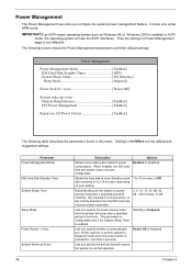
... Suspend Power Off or Suspend Chapter 2 Options Enabled or Disabled 1 to powersaving mode after a specified period of inactivity. Any keyboard or mouse action, or any activity detected from the IRQ channels resumes system operation. Parameter Power Management Mode IDE Hard Disk Standby Timer System Sleep Timer Sleep Mode Power Switch < 4 sec. Settings in this menu. It works only under APM mode. Allows the hard disk to enter Standby mode after a specified period of inactivity. Power Management The Power Management menu lets...
... Suspend Power Off or Suspend Chapter 2 Options Enabled or Disabled 1 to powersaving mode after a specified period of inactivity. Any keyboard or mouse action, or any activity detected from the IRQ channels resumes system operation. Parameter Power Management Mode IDE Hard Disk Standby Timer System Sleep Timer Sleep Mode Power Switch < 4 sec. Settings in this menu. It works only under APM mode. Allows the hard disk to enter Standby mode after a specified period of inactivity. Power Management The Power Management menu lets...
Power SC Service Guide
Page 72
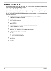
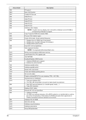
... numeric co-processor and cache memory subsystem ! Power-On Self-Test (POST) Each time you turn on the system, the Power-on the main board that boots the system, initializes and diagnoses the system components, and controls the operation of the power-on screen, generates a check point code at power-on, it displays error messages on password option. Onboard serial interface controller ! PS/2-compatible mouse port ! USB port 64 Chapter 4 Interrupt system ! Keyboard and auxiliary device controllers !
... numeric co-processor and cache memory subsystem ! Power-On Self-Test (POST) Each time you turn on the system, the Power-on the main board that boots the system, initializes and diagnoses the system components, and controls the operation of the power-on screen, generates a check point code at power-on, it displays error messages on password option. Onboard serial interface controller ! PS/2-compatible mouse port ! USB port 64 Chapter 4 Interrupt system ! Keyboard and auxiliary device controllers !
Power SC Service Guide
Page 73
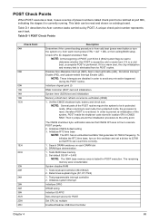
... shutdown code stored in location 0Fh in protected mode. Set default SS:SP = 0:400 NOTE: The 384K base memory area is tested for POST Set CPU (s) multiple Enables/Disables USB Host Controller Chapter 4 65 The remaining memory ares is tested later. Determines keyboard type (AT, XT, PS/2) 1. This latch can count time correctly. 1. To initialize the RTC time base, turn the system on each task. DRAM type determination 1. Tests keyboard controller (8041...
... shutdown code stored in location 0Fh in protected mode. Set default SS:SP = 0:400 NOTE: The 384K base memory area is tested for POST Set CPU (s) multiple Enables/Disables USB Host Controller Chapter 4 65 The remaining memory ares is tested later. Determines keyboard type (AT, XT, PS/2) 1. This latch can count time correctly. 1. To initialize the RTC time base, turn the system on each task. DRAM type determination 1. Tests keyboard controller (8041...
Power SC Service Guide
Page 74
... Initializes parallel port(s) Initializes parallel port(s) Reset math coprocessor Check and initialize pointing device Set security status Prepare entering SETUP for user pressing CTRL + ALT DEL. Tests and initializes FDD 2. transfer speed, mode,....) 2. POSt detects I /O subsystem. Copy F-seg from ROM into shadow RAM Process VGA shadow region Check CPU brand, ID and external frequency 1. Memory test (except the 384K base memory) Load Pentium Pro CPU update code Test SM RAM Enables/Disables USB Function 1. Initializes I /O ROM Sets time and...
... Initializes parallel port(s) Initializes parallel port(s) Reset math coprocessor Check and initialize pointing device Set security status Prepare entering SETUP for user pressing CTRL + ALT DEL. Tests and initializes FDD 2. transfer speed, mode,....) 2. POSt detects I /O subsystem. Copy F-seg from ROM into shadow RAM Process VGA shadow region Check CPU brand, ID and external frequency 1. Memory test (except the 384K base memory) Load Pentium Pro CPU update code Test SM RAM Enables/Disables USB Function 1. Initializes I /O ROM Sets time and...
Power SC Service Guide
Page 76
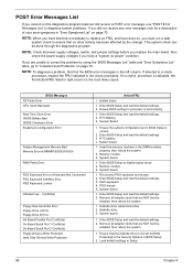
... that are NOT factory- Conflict(s) Floppy Disk Controller Error Floppy Drive A Error Floppy Drive B Error On Board Parallel Port Conflict(s) On Board Serial Port 1 Conflict(s) On Board Serial Port 2 Conflict(s) Floppy Drive(s) Write Protected Hard Disk Drive(s) Write Protected Action/FRU 1. Insert the memory modules in BIOS Setup. 2. System board. 1. Memory module 3. Re-connect PS/2 keyboard and mouse. 2. Enter BIOS Setup and load the default settings. 3. PS/2 mouse 5. System board 1. Enter BIOS Setup and load the default settings. 2. Remove all adapter cards that no other...
... that are NOT factory- Conflict(s) Floppy Disk Controller Error Floppy Drive A Error Floppy Drive B Error On Board Parallel Port Conflict(s) On Board Serial Port 1 Conflict(s) On Board Serial Port 2 Conflict(s) Floppy Drive(s) Write Protected Hard Disk Drive(s) Write Protected Action/FRU 1. Insert the memory modules in BIOS Setup. 2. System board. 1. Memory module 3. Re-connect PS/2 keyboard and mouse. 2. Enter BIOS Setup and load the default settings. 3. PS/2 mouse 5. System board 1. Enter BIOS Setup and load the default settings. 2. Remove all adapter cards that no other...
Power SC Service Guide
Page 77
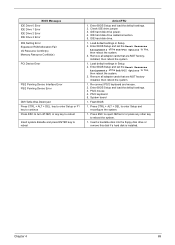
... a hard disk is installed. Remove all adapter cards that are NOT factoryinstalled, then reboot the system 1. Chapter 4 69 IDE hard disk drive cable/connection. 5. IDE hard disk drive. 1. Load default settings in Setup. 2. Press ESC to reject NMI error or press any key to reboot Insert system diskette and press ENTER key to reboot Action/FRU 1. Check IDE drive jumper. 3. Flash BIOS 1. Load default settings in Setup. 2. Press CTRL + ALT + DEL to reboot the system. 1. Enter BIOS Setup and set the Reset Resource Assignments of the PnP/PCI Options...
... a hard disk is installed. Remove all adapter cards that are NOT factoryinstalled, then reboot the system 1. Chapter 4 69 IDE hard disk drive cable/connection. 5. IDE hard disk drive. 1. Load default settings in Setup. 2. Press ESC to reject NMI error or press any key to reboot Insert system diskette and press ENTER key to reboot Action/FRU 1. Check IDE drive jumper. 3. Flash BIOS 1. Load default settings in Setup. 2. Press CTRL + ALT + DEL to reboot the system. 1. Enter BIOS Setup and set the Reset Resource Assignments of the PnP/PCI Options...
Power SC Service Guide
Page 79
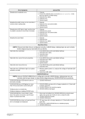
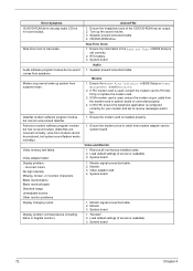
...-ROM driver is configured correctly in the Security Options of hard disk LED connector. 2. Ensure the diskette drive is not set to unload the disk. 2. Diskette drive cable. 4. Diskette 2. Hard disk drive cable. 3. Hard drive LED cable. Error Symptom Action/FRU Diskette drive read and there are no messages are set correctly and its eject button is pressed and held. 1. Hard disk drive LED fails to reinstall disc. Software displays a reading CD/DVD error. 1. System board Hard Disk Drive NOTE: Ensure hard disk drive is configured correctly in BIOS Setup, cable/jumper...
...-ROM driver is configured correctly in the Security Options of hard disk LED connector. 2. Ensure the diskette drive is not set to unload the disk. 2. Diskette drive cable. 4. Diskette 2. Hard disk drive cable. 3. Hard drive LED cable. Error Symptom Action/FRU Diskette drive read and there are no messages are set correctly and its eject button is pressed and held. 1. Hard disk drive LED fails to reinstall disc. Software displays a reading CD/DVD error. 1. System board Hard Disk Drive NOTE: Ensure hard disk drive is configured correctly in BIOS Setup, cable/jumper...
Power SC Service Guide
Page 80
... monitor(bright) Distorted image Unreadable monitor Other monitor problems Display changing colors. CD/DVD-ROM drive. Real-Time Clock 1. If ISA modem card is used , reinsert the modem card to receive messages and/or fax. 1. Remove all non-factory-installed cards. 2. System board 1. System board 1. System board 72 Chapter 4 Ensure the headphone jack of BIOS Setup is set to PCI slot firmly or replace the modem card. 3. Monitor 3. Real-time clock is readable). 3. "Monitor". 2. voice from suspend mode. Load default settings (if screen...
... monitor(bright) Distorted image Unreadable monitor Other monitor problems Display changing colors. CD/DVD-ROM drive. Real-Time Clock 1. If ISA modem card is used , reinsert the modem card to receive messages and/or fax. 1. Remove all non-factory-installed cards. 2. System board 1. System board 1. System board 72 Chapter 4 Ensure the headphone jack of BIOS Setup is set to PCI slot firmly or replace the modem card. 3. Monitor 3. Real-time clock is readable). 3. "Monitor". 2. voice from suspend mode. Load default settings (if screen...
Power SC Service Guide
Page 81
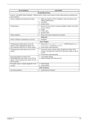
... printer driver is not set to OFF. 2. Executing software shutdown from Recovery CD. Reload software from Windows98 Start menu does not turn off the system. (Only pressing power switch can turn on keyboard do not work. 1. Power Supply 2. Printer. 3. Refer to the printer service manual. 2. Keyboard Power Supply Pressing power switch does not turn off the system.) 1. in BIOS Setup of the machine, just above the connector for the printer. System board. Power switch cable assembly Pressing power switch does not turn off system...
... printer driver is not set to OFF. 2. Executing software shutdown from Recovery CD. Reload software from Windows98 Start menu does not turn off the system. (Only pressing power switch can turn on keyboard do not work. 1. Power Supply 2. Printer. 3. Refer to the printer service manual. 2. Keyboard Power Supply Pressing power switch does not turn off the system.) 1. in BIOS Setup of the machine, just above the connector for the printer. System board. Power switch cable assembly Pressing power switch does not turn off system...
Power SC Service Guide
Page 82
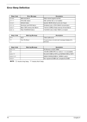
..."1" means short beep 74 Chapter 4 Error Beep Definition Beep Code 2-1-2-2 2-1-1-1 2-1-2-1 2-1-1-2 2-2-2-1 2-2-1-2 Error Message DMA test failure 8742 KBC failure Refresh failure Shutdown byte R/W failure Base 128K memory test failure Flash ROM BIOS failure Description DMA internal register test fail KBC self test fail or not installed System DRAM refresh cycle out of base memory r/w test failure The BIOS code in flash ROM is corrupted Beep Code 2-1-1 1-1 Warning Message VGA Com Port Boot Description Video buffer error Console does not exist and message displayed to terminal Beep Code...
..."1" means short beep 74 Chapter 4 Error Beep Definition Beep Code 2-1-2-2 2-1-1-1 2-1-2-1 2-1-1-2 2-2-2-1 2-2-1-2 Error Message DMA test failure 8742 KBC failure Refresh failure Shutdown byte R/W failure Base 128K memory test failure Flash ROM BIOS failure Description DMA internal register test fail KBC self test fail or not installed System DRAM refresh cycle out of base memory r/w test failure The BIOS code in flash ROM is corrupted Beep Code 2-1-1 1-1 Warning Message VGA Com Port Boot Description Video buffer error Console does not exist and message displayed to terminal Beep Code...

Power SC Service Guide
Page 84
... all cables and connectors for proper installation. 9. External devices ! Any adapter card (modem card, LAN card or video card, if installed) ! Diskette drive ! Check the power supply voltages. Processor ! Load default settings in "or "Error Symptoms List" on page 68 . Check all adapter card jumper positions. 7. Power off the system unit. 3. Perform the following steps: 2. Check all system board jumper positions and switch settings. 6. If the jumpers, switches and voltage settings are correct continue with this check: 1. CD/DVD-ROM drive ! Hard disk drive ! If...
... all cables and connectors for proper installation. 9. External devices ! Any adapter card (modem card, LAN card or video card, if installed) ! Diskette drive ! Check the power supply voltages. Processor ! Load default settings in "or "Error Symptoms List" on page 68 . Check all adapter card jumper positions. 7. Power off the system unit. 3. Perform the following steps: 2. Check all system board jumper positions and switch settings. 6. If the jumpers, switches and voltage settings are correct continue with this check: 1. CD/DVD-ROM drive ! Hard disk drive ! If...
Power SC Service Guide
Page 115
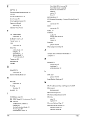
... IDE1 connector 78 IDE2 connector 78 IDSEL 17 Interface audio 15 Floppy disk drive 16 IDE 15 Video 14 Intrusion jumper 78, 80 IRQ Assignment Map 18 J Jumper and Connector Information 77 Jumpers 77 K keyboard 9 cursor keys 9 lock keys 9 windows-keys 10 L LAN LED jumper 78, 80 Load Default Settings 47 M Machine Disassembly and Replacement 51 Main board Removing 60 Main board Layout 6 Mechanical Specifications 19 Memory size 13 system 13 Memory Address Map 17 Memory/Cache Options 43 external cache 44 internal cache...
... IDE1 connector 78 IDE2 connector 78 IDSEL 17 Interface audio 15 Floppy disk drive 16 IDE 15 Video 14 Intrusion jumper 78, 80 IRQ Assignment Map 18 J Jumper and Connector Information 77 Jumpers 77 K keyboard 9 cursor keys 9 lock keys 9 windows-keys 10 L LAN LED jumper 78, 80 Load Default Settings 47 M Machine Disassembly and Replacement 51 Main board Removing 60 Main board Layout 6 Mechanical Specifications 19 Memory size 13 system 13 Memory Address Map 17 Memory/Cache Options 43 external cache 44 internal cache...

Power SC Service Guide
Page 116
... Controller 35 USB Legacy Mode 35 Online Support Information 103 Overview 1 P Parallel Port 16 Parallel/VGA/serial port 2 connector 78 Password bypassing 42 changing 42 removing 42 setting 41 PCI INTx# 17 PCI Slot IRQ 17 PnP PCI Options Graphics Aperture Size 45 IRQ Sharing 45 PCI IRQ Setting 45 Plug and Play OS 46 Reset Resource Assignments 46 VGA Palette Snoop 45 ports left panel 5 POST 64 Post Check Points 65 POST Error Messages List 64 Power LED jumper 78 Power Management...
... Controller 35 USB Legacy Mode 35 Online Support Information 103 Overview 1 P Parallel Port 16 Parallel/VGA/serial port 2 connector 78 Password bypassing 42 changing 42 removing 42 setting 41 PCI INTx# 17 PCI Slot IRQ 17 PnP PCI Options Graphics Aperture Size 45 IRQ Sharing 45 PCI IRQ Setting 45 Plug and Play OS 46 Reset Resource Assignments 46 VGA Palette Snoop 45 ports left panel 5 POST 64 Post Check Points 65 POST Error Messages List 64 Power LED jumper 78 Power Management...
Power SC Service Guide
Page 117
... 26 Internal cache size 26 parallel port 27 Processor 26 Processor speed 26 PS/2 mouse 27 serial port 1 27 serial port 2 27 total memory 27 System Security disk drive controller 40 floppy disk drive 40 hard disk drive 40 Processor Serial Number 40 Supervisor password 40 User password 40 System Specifications 1 design 2, 3 Features 2 System Utilities 23 Abort Settings Change 48 Advanced Options 43 Boot Options 38 Date 39 Disk Drives 30 Exiting Setup 49 108 Load Default Settings 47 Memory/Cache Options 43 Onboard Peripherals 33 PnP/PCI Options 45 Power Management 36...
... 26 Internal cache size 26 parallel port 27 Processor 26 Processor speed 26 PS/2 mouse 27 serial port 1 27 serial port 2 27 total memory 27 System Security disk drive controller 40 floppy disk drive 40 hard disk drive 40 Processor Serial Number 40 Supervisor password 40 User password 40 System Specifications 1 design 2, 3 Features 2 System Utilities 23 Abort Settings Change 48 Advanced Options 43 Boot Options 38 Date 39 Disk Drives 30 Exiting Setup 49 108 Load Default Settings 47 Memory/Cache Options 43 Onboard Peripherals 33 PnP/PCI Options 45 Power Management 36...
Power Sc User's Guide
Page 49
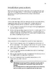
... component connector. Always observe the following precautions before you wish to it before you install any component: 1 2 3 4 5 Turn off your processor, disk drives, expansion boards, and other components. Preinstallation instructions Always observe the following sections for specific instructions on page 41. Open your computer according to the instructions on "Opening your computer" on the component you install a system component: 1 2 Do not remove a component from the power...
... component connector. Always observe the following precautions before you wish to it before you install any component: 1 2 3 4 5 Turn off your processor, disk drives, expansion boards, and other components. Preinstallation instructions Always observe the following sections for specific instructions on page 41. Open your computer according to the instructions on "Opening your computer" on the component you install a system component: 1 2 Do not remove a component from the power...


