
PD100 and PD120 Service Guide
Page 12
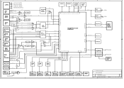
... THER_ERR I2C Bus Audio Out R/L 2 / 5 DVD KEY / GPI Expander 2 / 2 Audio / OUT Rear IR Rear IR Data 2 / 1 +/ PWM FET PWM FET Motor Driver 4 Front IR Front IR Data 2 4 / PC DVI RS-232 2 RS-232 WS RS-232 / VGA RS-232 A FAN 1 FAN 2 System Blower B CW Motor Photo Sensor... Thermal Switch C Thermal Sensor Lamp Driver LAMP D Title Size B Date: Coretronic Corporation BLOCK DIAGRAM Document Number PD120D MB SCHEMATIC Thursday, August 04, 2005 Rev D Sheet 1 of 19 E
... THER_ERR I2C Bus Audio Out R/L 2 / 5 DVD KEY / GPI Expander 2 / 2 Audio / OUT Rear IR Rear IR Data 2 / 1 +/ PWM FET PWM FET Motor Driver 4 Front IR Front IR Data 2 4 / PC DVI RS-232 2 RS-232 WS RS-232 / VGA RS-232 A FAN 1 FAN 2 System Blower B CW Motor Photo Sensor... Thermal Switch C Thermal Sensor Lamp Driver LAMP D Title Size B Date: Coretronic Corporation BLOCK DIAGRAM Document Number PD120D MB SCHEMATIC Thursday, August 04, 2005 Rev D Sheet 1 of 19 E
PD100 and PD120 Service Guide
Page 16
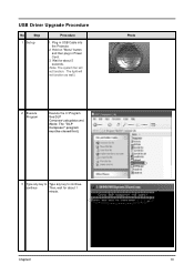
continue Then, wait for about 1 minute. Wait for about 5 seconds. (Note: The system fan will not function as well.) 2 Execute Program Execute the C:\Program files\DLP Composer\usbupdata.cmd. (Note: The "DLP Composer" program must be closed first.) Photo 3 Type any key to Type any key to continue. USB Driver Upgrade Procedure No Step 1 Set-up Procedure 1. Hold on "Menu" button and then plug in USB Cable into the Projector. 2. The light will not function. Chapter2 10 Plug in Power Cord. 3.
continue Then, wait for about 1 minute. Wait for about 5 seconds. (Note: The system fan will not function as well.) 2 Execute Program Execute the C:\Program files\DLP Composer\usbupdata.cmd. (Note: The "DLP Composer" program must be closed first.) Photo 3 Type any key to Type any key to continue. USB Driver Upgrade Procedure No Step 1 Set-up Procedure 1. Hold on "Menu" button and then plug in USB Cable into the Projector. 2. The light will not function. Chapter2 10 Plug in Power Cord. 3.

PD100 and PD120 Service Guide
Page 17
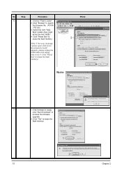
If not, repeart installed Step 1~5. Select "Properties" on the desktop. 2. Device Manager 11 Chapter 2 Right click "My computer" on the popup menu to ensure "DDP2000" & "DDP2000" and "WinDriver" are "Windriver" are properly properly installed. Photo 5 Device Manager 1. No Step 4 Update Successfully Procedure Click "OK". The USB driver is updated successfully. Choose "Hardware" and then click "Device Manager". 6 Ensure Click "Jungo" to launch the "System Properties" window. 3.
If not, repeart installed Step 1~5. Select "Properties" on the desktop. 2. Device Manager 11 Chapter 2 Right click "My computer" on the popup menu to ensure "DDP2000" & "DDP2000" and "WinDriver" are "Windriver" are properly properly installed. Photo 5 Device Manager 1. No Step 4 Update Successfully Procedure Click "OK". The USB driver is updated successfully. Choose "Hardware" and then click "Device Manager". 6 Ensure Click "Jungo" to launch the "System Properties" window. 3.
PD100 and PD120 Service Guide
Page 19
...Bus" to erase the flash memory. 1 2 13 Chapter 2 Click "Yes" to erase the flash memory. (Note: If the error message "cannot open USB driver No projectors found" appears, please unplug the USB Cable and replug, then re-do 4. No Step Procedure 6 1. If the firmware is ready, click "Start ..." to erase the flash memory.) Photo 2 3 4 Note: 7 1. Click "Reset Bus" to process the firmware upgrade. 2. Click "Browse" to search the firmware file. (PD100 / PD120) 3. Select the item "Skip Boot Loader Area (load 1 all but the first 16KB)." 4. Choose "Flash Loader" 2.
...Bus" to erase the flash memory. 1 2 13 Chapter 2 Click "Yes" to erase the flash memory. (Note: If the error message "cannot open USB driver No projectors found" appears, please unplug the USB Cable and replug, then re-do 4. No Step Procedure 6 1. If the firmware is ready, click "Start ..." to erase the flash memory.) Photo 2 3 4 Note: 7 1. Click "Reset Bus" to process the firmware upgrade. 2. Click "Browse" to search the firmware file. (PD100 / PD120) 3. Select the item "Skip Boot Loader Area (load 1 all but the first 16KB)." 4. Choose "Flash Loader" 2.

PD100 and PD120 Service Guide
Page 34
Chapter 3 28 Remove Lamp Driver No Procedure 1 Unscrew 4 screws. Photo 2 Unplug 2 connectors to separate the Lamp Driver Housing. 9. Note: When assembling the LVPS, please be aware of the LVPS connector connection. (the shorter wire should be connected to the LVPS, and the longer wire should be connected to the Lamp Driver.) 3 Unscrew 4 screws to remove the Lamp Driver Module.
Chapter 3 28 Remove Lamp Driver No Procedure 1 Unscrew 4 screws. Photo 2 Unplug 2 connectors to separate the Lamp Driver Housing. 9. Note: When assembling the LVPS, please be aware of the LVPS connector connection. (the shorter wire should be connected to the LVPS, and the longer wire should be connected to the Lamp Driver.) 3 Unscrew 4 screws to remove the Lamp Driver Module.
PD100 and PD120 Service Guide
Page 43
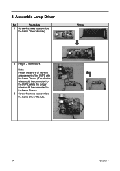
Assemble Lamp Driver No Procedure 1 Screw 4 screws to assemble the Lamp Driver Module. 37 Chapter 3 while the longer wire should be connected to the Lamp Driver.) 3 Screw 4 screws to assemble the Lamp Driver Housing. Photo 2 Plug in 2 connectors. Note: Please be aware of the wire arrangement of the LVPS with the Lamp Driver. (The shorter wire should be connected to the LVPS; 4.
Assemble Lamp Driver No Procedure 1 Screw 4 screws to assemble the Lamp Driver Module. 37 Chapter 3 while the longer wire should be connected to the Lamp Driver.) 3 Screw 4 screws to assemble the Lamp Driver Housing. Photo 2 Plug in 2 connectors. Note: Please be aware of the wire arrangement of the LVPS with the Lamp Driver. (The shorter wire should be connected to the LVPS; 4.
PD100 and PD120 Service Guide
Page 53
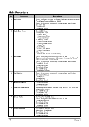
...'s because of the DMD Chip and the DMD Board did not assemble properly - Check Thermal Sensor - Color Wheel - Check Photo Sensor d. No Power - Check Lamp Driver - Check DMD Board - Check Fan Module - Check Main Board b. Check Main Board - Ensure the Signal Cable and Source work as well - Check Color Wheel Chapter...
...'s because of the DMD Chip and the DMD Board did not assemble properly - Check Thermal Sensor - Color Wheel - Check Photo Sensor d. No Power - Check Lamp Driver - Check DMD Board - Check Fan Module - Check Main Board b. Check Main Board - Ensure the Signal Cable and Source work as well - Check Color Wheel Chapter...
PD100 and PD120 Service Guide
Page 62
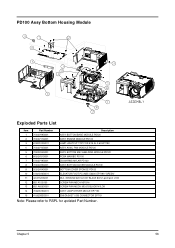
...MECH M3*5 Ni SCREW PAN MECH M2.6*5 BLACK NYLOK 14 70.82G19G001 ASSY LAMP DRIVER MDULE EP7190 15 41.82G03G001 EMI GASKET USB CONNECTOR EP719 Note: Please refer to RSPL for updated Part Number. PD100 Assy Bottom Housing Module Exploded Parts List Item 1 2 3 Part Number 70....82V09G001 70.82V17G001 61.82G12G001 Description ASSY BOTTOM BASE MODULE PD120 ASSY ENGINE MODULE PD100 LAMP LIGHTCUT TOP FOR E19 AL 0.6t EP7190 4 70.82V10G001 ASSY AXIAL FAN MODULE PD120 5 70.82V04G001 6 80.82V51G001 7 51.82V19G001 ...
...MECH M3*5 Ni SCREW PAN MECH M2.6*5 BLACK NYLOK 14 70.82G19G001 ASSY LAMP DRIVER MDULE EP7190 15 41.82G03G001 EMI GASKET USB CONNECTOR EP719 Note: Please refer to RSPL for updated Part Number. PD100 Assy Bottom Housing Module Exploded Parts List Item 1 2 3 Part Number 70....82V09G001 70.82V17G001 61.82G12G001 Description ASSY BOTTOM BASE MODULE PD120 ASSY ENGINE MODULE PD100 LAMP LIGHTCUT TOP FOR E19 AL 0.6t EP7190 4 70.82V10G001 ASSY AXIAL FAN MODULE PD120 5 70.82V04G001 6 80.82V51G001 7 51.82V19G001 ...

PD100 and PD120 Service Guide
Page 63
... "GREEN' W.A. GROUND #20 UL1007 BLACK 80mm p3.0/p3.0 LT20 SCREW PAN MECH M3*5 Ni SCREW PAN MECH M2.6*5 BLACK NYLOK 14 70.82G19G001 ASSY LAMP DRIVER MDULE EP7190 15 41.82G03G001 EMI GASKET USB CONNECTOR EP719 Note: Please refer to RSPL for updated Part Number. 57 Chapter 5
... "GREEN' W.A. GROUND #20 UL1007 BLACK 80mm p3.0/p3.0 LT20 SCREW PAN MECH M3*5 Ni SCREW PAN MECH M2.6*5 BLACK NYLOK 14 70.82G19G001 ASSY LAMP DRIVER MDULE EP7190 15 41.82G03G001 EMI GASKET USB CONNECTOR EP719 Note: Please refer to RSPL for updated Part Number. 57 Chapter 5


