
PD100 and PD120 Service Guide
Page 6
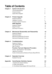
... System Introduction 1 Technical Specification 1 Product Overview 2 System Block Diagram 6 Chapter 2 Firware Upgrade 7 Equipment Needed 7 Installation Procedure 8 Firmware Upgrade Procedure 12 EDID Upgrade 15 Equipment Needed 15 Setup Procedure 16 EDID Key-in Procedure 16 Chapter 3 Mechanical Disassembly and Reassembly 19 ... / Test Condition 49 Inspection Procecdure 50 Guide to Entering Service Mode and Factory Reset (PD100) 53 Chapter 5 Exploded Overview 54 Exploded Overview 54 Appendix Serial Number Definition System 80 I. The Different Parts between...
... System Introduction 1 Technical Specification 1 Product Overview 2 System Block Diagram 6 Chapter 2 Firware Upgrade 7 Equipment Needed 7 Installation Procedure 8 Firmware Upgrade Procedure 12 EDID Upgrade 15 Equipment Needed 15 Setup Procedure 16 EDID Key-in Procedure 16 Chapter 3 Mechanical Disassembly and Reassembly 19 ... / Test Condition 49 Inspection Procecdure 50 Guide to Entering Service Mode and Factory Reset (PD100) 53 Chapter 5 Exploded Overview 54 Exploded Overview 54 Appendix Serial Number Definition System 80 I. The Different Parts between...
PD100 and PD120 Service Guide
Page 13
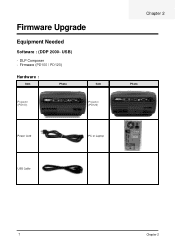
Firmware (PD100 / PD120) Hardware : Item Photo Item Projector (PD100) Projector (PD120) Chapter 2 Photo Power Cord PC or Laptop USB Cable 7 Chapter 2 DLP Composer - USB) - Firmware Upgrade Equipment Needed Software : (DDP 2000-
Firmware (PD100 / PD120) Hardware : Item Photo Item Projector (PD100) Projector (PD120) Chapter 2 Photo Power Cord PC or Laptop USB Cable 7 Chapter 2 DLP Composer - USB) - Firmware Upgrade Equipment Needed Software : (DDP 2000-
PD100 and PD120 Service Guide
Page 18
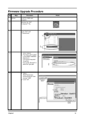
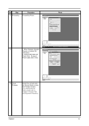
Click "Library". 2. The library path located in the default installation directory is: C:\Program Files\DLP Composer. Select "Edit\Preferences\ Communications" and choose "USB". 2. Chapter2 1 USB Vendor: Ux451 Product: Ox2000 2 OK 12 If not, press "Browse" to select the right path. 5 1. Firmware Upgrade Procedure No Step 1 Set-up 2 Procedure Link PC COM1 and projector Execute the "DLP ComposeTM" file.. 3 Click "Edit" and "Preferences". 1 Photo 2 4 1. Click "OK".
Click "Library". 2. The library path located in the default installation directory is: C:\Program Files\DLP Composer. Select "Edit\Preferences\ Communications" and choose "USB". 2. Chapter2 1 USB Vendor: Ux451 Product: Ox2000 2 OK 12 If not, press "Browse" to select the right path. 5 1. Firmware Upgrade Procedure No Step 1 Set-up 2 Procedure Link PC COM1 and projector Execute the "DLP ComposeTM" file.. 3 Click "Edit" and "Preferences". 1 Photo 2 4 1. Click "OK".
PD100 and PD120 Service Guide
Page 19
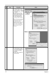
..., click "Start Download" to erase the flash memory.) Photo 2 3 4 Note: 7 1. Click "Browse" to erase the flash memory. 1 2 13 Chapter 2 Click "Yes" to search the firmware file. (PD100 / PD120) 3. Choose "Flash Loader" 2. Click "Reset Bus" to erase the flash memory. (Note: If the error message "cannot open USB driver No projectors found" appears...
..., click "Start Download" to erase the flash memory.) Photo 2 3 4 Note: 7 1. Click "Browse" to erase the flash memory. 1 2 13 Chapter 2 Click "Yes" to search the firmware file. (PD100 / PD120) 3. Choose "Flash Loader" 2. Click "Reset Bus" to erase the flash memory. (Note: If the error message "cannot open USB driver No projectors found" appears...
PD100 and PD120 Service Guide
Page 20
No Step 8 Proceeding Procedure Proceeding Picture Photo 9 1. Unplug USB Cable and Power Cord. When Firmware Upgrade Process is finished, the LED power 2. Re-plug in Power Cable after 3 mins. 10 Check Firmware Restart the unit and enter the Service Mode to check the Firmware Version. (For entering Service Mode, please refer to Chapter 4 Function Test and Alignment Procedure.) Chapter2 14
No Step 8 Proceeding Procedure Proceeding Picture Photo 9 1. Unplug USB Cable and Power Cord. When Firmware Upgrade Process is finished, the LED power 2. Re-plug in Power Cable after 3 mins. 10 Check Firmware Restart the unit and enter the Service Mode to check the Firmware Version. (For entering Service Mode, please refer to Chapter 4 Function Test and Alignment Procedure.) Chapter2 14
PD100 and PD120 Service Guide
Page 57
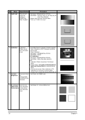
...Calibration - Test Pattern : Master - Test Pattern : White (Top) Black (Bottom) Note: 1. Guide to leave the Service Mode after all. Test Signal : 800x600@75Hz (PD100) - Choose and access Video Calibration & PC Calibration for entering Service Mode. 3. Please check and see if the light leaks. - Please refer to Bottom) - Test Pattern... Pattern should be done as well. - PC Calibration - No Step 7 Light Leak Specification Procedure The unit can't accept the leakage is changed, firmware upgrade, Video Calibration & ADC Calibration should be in Service Mode.
...Calibration - Test Pattern : Master - Test Pattern : White (Top) Black (Bottom) Note: 1. Guide to leave the Service Mode after all. Test Signal : 800x600@75Hz (PD100) - Choose and access Video Calibration & PC Calibration for entering Service Mode. 3. Please check and see if the light leaks. - Please refer to Bottom) - Test Pattern... Pattern should be done as well. - PC Calibration - No Step 7 Light Leak Specification Procedure The unit can't accept the leakage is changed, firmware upgrade, Video Calibration & ADC Calibration should be in Service Mode.

