User Manual
Page 18
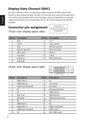
... 15-pin color display signal cable 1 5 6 10 11 15 PIN No. for example, supported resolutions and corresponding timing. Description 1 Red 2 Green 3 Blue 4 Monitor ground 5 DDC-return 6 R-ground 7 G-ground 8 B-ground PIN No. Description 13 NC 14 +5 V power 15 DVI detect 16 Hot-plug detection 17 TMDS data... 018 TMDS data 0+ 19 TMDS data 0/5 shield 20 NC 21 NC 22 TMDS clock shield 23 TMDS clock+ 24 DDC TMDS clock- Description 9 +5 V 10 Logic ground 11 Monitor ground 12 DDC-serial data 13 H-sync 14 V-sync 15 DDC-serial clock 24-pin...
... 15-pin color display signal cable 1 5 6 10 11 15 PIN No. for example, supported resolutions and corresponding timing. Description 1 Red 2 Green 3 Blue 4 Monitor ground 5 DDC-return 6 R-ground 7 G-ground 8 B-ground PIN No. Description 13 NC 14 +5 V power 15 DVI detect 16 Hot-plug detection 17 TMDS data... 018 TMDS data 0+ 19 TMDS data 0/5 shield 20 NC 21 NC 22 TMDS clock shield 23 TMDS clock+ 24 DDC TMDS clock- Description 9 +5 V 10 Logic ground 11 Monitor ground 12 DDC-serial data 13 H-sync 14 V-sync 15 DDC-serial clock 24-pin...


