
Service Guide
Page 7
... Disassembly 29 Removing the Side Panel 30 Removing the Front Bezel 31 Removing the Heat Sink Fan Assembly 32 Removing the Processor 33 Removing the Optical Drive 34 Removing the Hard Disk Drive 37 Removing the Power Supply 38 Removing the Memory Modules 40 Removing the TV Tuner Card 41 Removing the VGA Card 42 Removing the Front I/O and Card Reader Boards 43 Removing the Mainboard 46 Hardware Diagnostic Procedure 49 Chapter 4 System Troubleshooting 49 System Check Procedures 50 Power System Check 50 System External...
... Disassembly 29 Removing the Side Panel 30 Removing the Front Bezel 31 Removing the Heat Sink Fan Assembly 32 Removing the Processor 33 Removing the Optical Drive 34 Removing the Hard Disk Drive 37 Removing the Power Supply 38 Removing the Memory Modules 40 Removing the TV Tuner Card 41 Removing the VGA Card 42 Removing the Front I/O and Card Reader Boards 43 Removing the Mainboard 46 Hardware Diagnostic Procedure 49 Chapter 4 System Troubleshooting 49 System Check Procedures 50 Power System Check 50 System External...
Service Guide
Page 9
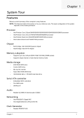
... MHz DIMM sockets • Supports single channel or dual-channel memory mode Media storage • DVD-ROM SATA drive • Combo SATA drive • Blu-ray disc rewriter • Super-Multi SATA DVD drive • 160/320/640 GB or 1 TB SATA hard disk drive Serial ATA controller • Embedded SATA controllers • Two SATA ports • eSATA port Audio • Realtek ALC888S 8-channel audio CODEC Networking • Intel WG82567V Gigabit NIC • One Gigabit Ethernet LAN port (RJ-45) Clock Generator...
... MHz DIMM sockets • Supports single channel or dual-channel memory mode Media storage • DVD-ROM SATA drive • Combo SATA drive • Blu-ray disc rewriter • Super-Multi SATA DVD drive • 160/320/640 GB or 1 TB SATA hard disk drive Serial ATA controller • Embedded SATA controllers • Two SATA ports • eSATA port Audio • Realtek ALC888S 8-channel audio CODEC Networking • Intel WG82567V Gigabit NIC • One Gigabit Ethernet LAN port (RJ-45) Clock Generator...

Service Guide
Page 10
...; Center speaker/subwoofer jack • Surround L/R speaker jack • Audio inside speaker jack or side speaker jack • S/PDIF port • HDMI port • eSATA port • Four USB 2.0 ports • Gigabit LAN port • VGA/monitor port Operating system and software • Operating system options: • Genuine Windows Vista® Ultimate (32/64-bit) • Genuine Windows Vista Home Premium (32/64-bit) • Windows 7 • Applications • Acer Empowering Technology (Acer eRecovery Management) • Acer Arcade Live • McAfee Internet...
...; Center speaker/subwoofer jack • Surround L/R speaker jack • Audio inside speaker jack or side speaker jack • S/PDIF port • HDMI port • eSATA port • Four USB 2.0 ports • Gigabit LAN port • VGA/monitor port Operating system and software • Operating system options: • Genuine Windows Vista® Ultimate (32/64-bit) • Genuine Windows Vista Home Premium (32/64-bit) • Windows 7 • Applications • Acer Empowering Technology (Acer eRecovery Management) • Acer Arcade Live • McAfee Internet...
Service Guide
Page 14
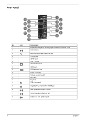
Icon 1 2 3 4 5 6 7 8 9 10 11 12 13 14 15 16 17 18 Component Expansion slot (Photo shows graphics card and TV tuner card) Line-out jack Microphone/speaker-out/line-in jack S/PDIF port eSATA port USB 2.0 ports VGA/monitor port HDMI port PS2 keyboard port Power connector Voltage selector switch Lock slot Key hole PS2 mouse port Gigabit LAN port (10/100/1000 Mbps) Rear speaker/surround out jack Center speaker/subwoofer jack Audio in or side speaker jack 6 Chapter 1 Rear Panel No.
Icon 1 2 3 4 5 6 7 8 9 10 11 12 13 14 15 16 17 18 Component Expansion slot (Photo shows graphics card and TV tuner card) Line-out jack Microphone/speaker-out/line-in jack S/PDIF port eSATA port USB 2.0 ports VGA/monitor port HDMI port PS2 keyboard port Power connector Voltage selector switch Lock slot Key hole PS2 mouse port Gigabit LAN port (10/100/1000 Mbps) Rear speaker/surround out jack Center speaker/subwoofer jack Audio in or side speaker jack 6 Chapter 1 Rear Panel No.

Service Guide
Page 17
... Run Setup messages, the battery may not be retained when power is a hardware configuration program built into the system ROM, called CMOS RAM. Chapter 2 9 NOTE: CMOS Setup Utility will need to run this utility under the following conditions. • When changing the system configuration settings • When redefining the communication ports to prevent any conflicts • When modifying the power management configuration • When changing the password or making other changes to the security setup • When a configuration error...
... Run Setup messages, the battery may not be retained when power is a hardware configuration program built into the system ROM, called CMOS RAM. Chapter 2 9 NOTE: CMOS Setup Utility will need to run this utility under the following conditions. • When changing the system configuration settings • When redefining the communication ports to prevent any conflicts • When modifying the power management configuration • When changing the password or making other changes to the security setup • When a configuration error...

Service Guide
Page 20
... Parameter Processor Type Processor Speed System Memory Product Name System Serial Number System BIOS Version BIOS Release Date Asset Tag Number :Move Enter:Select +/-/:Value F1:General Help F9:Optimized Defaults ESC:Exit F10:Save Description Type of system memory installed on the system. Total size of CPU installed on the system. Version number of the system. These entries are for your reference only and are not user-configurable. Product...
... Parameter Processor Type Processor Speed System Memory Product Name System Serial Number System BIOS Version BIOS Release Date Asset Tag Number :Move Enter:Select +/-/:Value F1:General Help F9:Optimized Defaults ESC:Exit F10:Save Description Type of system memory installed on the system. Total size of CPU installed on the system. Version number of the system. These entries are for your reference only and are not user-configurable. Product...

Service Guide
Page 22
...network devices. When disabled, the diagnostic screen displays during startup. Press Enter to access the Network Device Priority submenu and specify the boot sequence from available CD/DVD drives. Advanced BIOS Features Quick Boot Quiet Boot 1st Boot device 2nd Boot device 3rd Boot device 4th Boot device ► Hard Disk Drive Priority ► Optical Disk Drive Priority ► Removable Device Priority ► Network Device Priority Bootup Num-Lock USB Beep Message CMOS Setup Utility Advanced BIOS Features [Enabled] [Enabled] [HDD:P0-ST3320813AS] [CD/DVD] [USB:Kingston DataT] [Network...
...network devices. When disabled, the diagnostic screen displays during startup. Press Enter to access the Network Device Priority submenu and specify the boot sequence from available CD/DVD drives. Advanced BIOS Features Quick Boot Quiet Boot 1st Boot device 2nd Boot device 3rd Boot device 4th Boot device ► Hard Disk Drive Priority ► Optical Disk Drive Priority ► Removable Device Priority ► Network Device Priority Bootup Num-Lock USB Beep Message CMOS Setup Utility Advanced BIOS Features [Enabled] [Enabled] [HDD:P0-ST3320813AS] [CD/DVD] [USB:Kingston DataT] [Network...

Service Guide
Page 23
... return to change the setting. When enabled, the processor disables code execution when a worm attempts to reduce power consumption. Select a graphic controller as a primary boot device. When disabled, the system operates at maximum CPU speed. Advanced Chipset Features Intel EIST Intel XD Bit Intel VT Memory Hole Remapping Primary Video Video Memory Size DVMT Mode DVMT/FIXED Memory size CMOS Setup Utility Advanced Chipset Features [Enabled] [Enabled] [Enabled] [Enabled] [Auto] [32MB] [DVMT] [256MB] Help Item Options Disabled Enabled :Move Enter:Select +/-/:Value...
... return to change the setting. When enabled, the processor disables code execution when a worm attempts to reduce power consumption. Select a graphic controller as a primary boot device. When disabled, the system operates at maximum CPU speed. Advanced Chipset Features Intel EIST Intel XD Bit Intel VT Memory Hole Remapping Primary Video Video Memory Size DVMT Mode DVMT/FIXED Memory size CMOS Setup Utility Advanced Chipset Features [Enabled] [Enabled] [Enabled] [Enabled] [Auto] [32MB] [DVMT] [256MB] Help Item Options Disabled Enabled :Move Enter:Select +/-/:Value...

Service Guide
Page 28
...password to change the User password. Type a new password then press Enter. 4. Type a password then press Enter. The password may consist up /down arrow keys to save the new password and close the Setup Utility. Type the original password then press Enter. 3. Supervisor password prevents unauthorized access to six alphanumeric characters (A-Z, a-z, 0-9) 3. Setting a system password 1. Indicates the status of the supervisor password. Press F10. 5. Select Yes to select password parameter (Change Supervisor Password or Change User Password) menu then press Enter. 2. BIOS...
...password to change the User password. Type a new password then press Enter. 4. Type a password then press Enter. The password may consist up /down arrow keys to save the new password and close the Setup Utility. Type the original password then press Enter. 3. Supervisor password prevents unauthorized access to six alphanumeric characters (A-Z, a-z, 0-9) 3. Setting a system password 1. Indicates the status of the supervisor password. Press F10. 5. Select Yes to select password parameter (Change Supervisor Password or Change User Password) menu then press Enter. 2. BIOS...

Service Guide
Page 51
.... 4. Open the cable retention clip and disconnect the SATA cable, LED cable, and the other end of the USB, and audio cables from the mainboard. See "Removing the Heat Sink Fan Assembly" on an X3810 sample. See "Removing the Processor" on front panel. 7. Please notice that X3910 does not have IEEE1394 port on page 33. 5. Disconnect one end of the USB, 1394, and audio cables from the I /O and Card Reader Boards 1. See "Removing...
.... 4. Open the cable retention clip and disconnect the SATA cable, LED cable, and the other end of the USB, and audio cables from the mainboard. See "Removing the Heat Sink Fan Assembly" on an X3810 sample. See "Removing the Processor" on front panel. 7. Please notice that X3910 does not have IEEE1394 port on page 33. 5. Disconnect one end of the USB, 1394, and audio cables from the I /O and Card Reader Boards 1. See "Removing...
Service Guide
Page 59
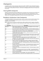
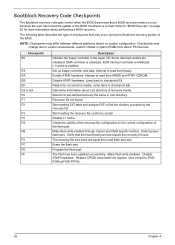
... display method is available. Perform keyboard controller BAT test. Disable CACHE before system memory is limited, since it only displays checkpoints that checkpoints may appear on a LED display. Set stack. Main BIOS checksum is forced. Store the Uncompressed pointer for future use in scratch CMOS. Give control to execute serial flash. Chapter 4 51 Checkpoints A checkpoint is currently executing. The BIOS outputs checkpoints throughout bootblock and Power-On Self Test...
... display method is available. Perform keyboard controller BAT test. Disable CACHE before system memory is limited, since it only displays checkpoints that checkpoints may appear on a LED display. Set stack. Main BIOS checksum is forced. Store the Uncompressed pointer for future use in scratch CMOS. Give control to execute serial flash. Chapter 4 51 Checkpoints A checkpoint is currently executing. The BIOS outputs checkpoints throughout bootblock and Power-On Self Test...
Service Guide
Page 60
... the update or the BIOS checksum is initialized. L1 cache is enabled. Disable ATAPI hardware. Checkpoint E0 E9 EA EB EF E9 or EA F0 F1 F2 F3 F5 FA FB F4 FC FD FF Description Initialize the floppy controller in the super I/O. Start reading the recovery file cluster by the recovery file. Make flash write enabled through chipset and OEM specific method. Restore...
... the update or the BIOS checksum is initialized. L1 cache is enabled. Disable ATAPI hardware. Checkpoint E0 E9 EA EB EF E9 or EA F0 F1 F2 F3 F5 FA FB F4 FC FD FF Description Initialize the floppy controller in the super I/O. Start reading the recovery file cluster by the recovery file. Make flash write enabled through chipset and OEM specific method. Restore...
Service Guide
Page 61
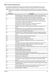
... that are based on default values and clear passwords. Initializes data variables that may change due to determine if battery power is OK and CMOS checksum is bad, update CMOS with power-on CMOS setup questions. Allocate memory for displaying text information. POST Code Checkpoints The POST code checkpoints are the largest set of checkpoints during the POST portion of the BIOS. Initializes the CPU. USB controllers are initialized at this...
... that are based on default values and clear passwords. Initializes data variables that may change due to determine if battery power is OK and CMOS checksum is bad, update CMOS with power-on CMOS setup questions. Allocate memory for displaying text information. POST Code Checkpoints The POST code checkpoints are the largest set of checkpoints during the POST portion of the BIOS. Initializes the CPU. USB controllers are initialized at this...

Service Guide
Page 62
.... Disables the system configuration display if needed / requested. Display boot option popup menu. Initialize the CPU's before booting to OS Loader (typically INT19h). 54 Chapter 4 Uninstall POST INT1Ch vector and INT09h vector. Display errors to limit memory test. Late POST initialization of runtime image preparation for Int 19 boot. Wait for error. Allocates memory for DEL or ESC keys to the user and gets the user response for user input at config display...
.... Disables the system configuration display if needed / requested. Display boot option popup menu. Initialize the CPU's before booting to OS Loader (typically INT19h). 54 Chapter 4 Uninstall POST INT1Ch vector and INT09h vector. Display errors to limit memory test. Late POST initialization of runtime image preparation for Int 19 boot. Wait for error. Allocates memory for DEL or ESC keys to the user and gets the user response for user input at config display...

Service Guide
Page 64
... system board speaker, commonly referred to the end user. In most cases, a checkpoint card is OK. VGA not installed or VGA error. This display method is limited, since it only displays checkpoints that occur after the video card has been activated. CMOS checksum error or CMOS battery loss occurs. Boot Block Beep Codes Number of the screen during POST. Base memory read error No Flash EPROM detected Flash Erase error Flash Program error 'AMIBOOT.ROM' file size error BIOS ROM image mismatch (file layout does...
... system board speaker, commonly referred to the end user. In most cases, a checkpoint card is OK. VGA not installed or VGA error. This display method is limited, since it only displays checkpoints that occur after the video card has been activated. CMOS checksum error or CMOS battery loss occurs. Boot Block Beep Codes Number of the screen during POST. Base memory read error No Flash EPROM detected Flash Erase error Flash Program error 'AMIBOOT.ROM' file size error BIOS ROM image mismatch (file layout does...

Service Guide
Page 66
... POST, but was unable to properly configure the device. Reboot and Select proper Boot device or Insert Boot Media in selected Boot device BIOS could not find a bootable device in the drive, but it is unable to properly control the motherboard's Gate A20 function, which controls access of the error. Boot Message Displayed Boot Failure ... Memory Message Displayed Gate20 Error Multi-Bit ECC Error Parity Error RAM R/W test failed CMOS Memory Size Wrong Description The BIOS is not configured as a bootable diskette.
... POST, but was unable to properly configure the device. Reboot and Select proper Boot device or Insert Boot Media in selected Boot device BIOS could not find a bootable device in the drive, but it is unable to properly control the motherboard's Gate A20 function, which controls access of the error. Boot Message Displayed Boot Failure ... Memory Message Displayed Gate20 Error Multi-Bit ECC Error Parity Error RAM R/W test failed CMOS Memory Size Wrong Description The BIOS is not configured as a bootable diskette.

Service Guide
Page 69
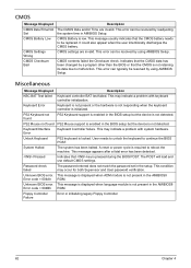
... applies to pass the Refresh Retrace Test. The message is most likely to appear when a brand new CPU is no FLASH part (System uses a PROM or EPROM). The NVRAM data used to store Plug'n'Play (PnP) data was not used for system configuration in a motherboard with system hardware. A PCI adapter generated an I /O resource conflict when configured by BIOS POST. BIOS POST found a PCI device in the system but was...
... applies to pass the Refresh Retrace Test. The message is most likely to appear when a brand new CPU is no FLASH part (System uses a PROM or EPROM). The NVRAM data used to store Plug'n'Play (PnP) data was not used for system configuration in a motherboard with system hardware. A PCI adapter generated an I /O resource conflict when configured by BIOS POST. BIOS POST found a PCI device in the system but was...
Service Guide
Page 70
... CMOS is pressed during the BIOS POST. PS2 Keyboard not found PS2 Mouse support is not detected. User needs to unlock the keyboard to malfunction. Pressed Indicates that the CMOS battery needs to reboot the machine. Unknown BIOS error. CMOS settings are invalid. This may indicate a problem with system hardware. The POST will load and use default CMOS settings. Password check failed The password entered does not match the password set in initializing legacy Floppy Controller. 62 Chapter 4 Unknown BIOS error...
... CMOS is pressed during the BIOS POST. PS2 Keyboard not found PS2 Mouse support is not detected. User needs to unlock the keyboard to malfunction. Pressed Indicates that the CMOS battery needs to reboot the machine. Unknown BIOS error. CMOS settings are invalid. This may indicate a problem with system hardware. The POST will load and use default CMOS settings. Password check failed The password entered does not match the password set in initializing legacy Floppy Controller. 62 Chapter 4 Unknown BIOS error...
Service Guide
Page 92
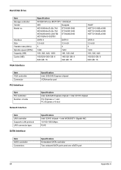
... Connector PCI Interface Specification Intel G43/G45 Express chipset VGA/monitor port Item PCI controller Number of slots Network Interface Specification Intel G43/G45 Express chipset + Intel ICH10 chipset PCI Express x 1 slot PCI Express x16 slot Item LAN controller Supports LAN protocol LAN connector type SATA Interface Specification Intel ICH10 chipset + Intel WG82567V Gigabit NIC 10/100/1000 Mbps RJ45 Item SATA controller Connectors Specification Embedded SATA controller Two onboard SATA ports and one eSATA port 84 Appendix A Hard Disk Drive Item Storage controller Vendor Model...
... Connector PCI Interface Specification Intel G43/G45 Express chipset VGA/monitor port Item PCI controller Number of slots Network Interface Specification Intel G43/G45 Express chipset + Intel ICH10 chipset PCI Express x 1 slot PCI Express x16 slot Item LAN controller Supports LAN protocol LAN connector type SATA Interface Specification Intel ICH10 chipset + Intel WG82567V Gigabit NIC 10/100/1000 Mbps RJ45 Item SATA controller Connectors Specification Embedded SATA controller Two onboard SATA ports and one eSATA port 84 Appendix A Hard Disk Drive Item Storage controller Vendor Model...
Service Guide
Page 93
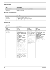
DVD +RW: 8x max. DVD-RAM: 12x max. CD-R: 48x max. DVD +R: 20x max. DVD-RW: 6x max. Audio Interface Item Audio controller Connectors Specification Realtek ALC888S 8-channel audio CODEC Audio 7.1 channel Keyboard and Input Devices Item Controller Connectors Optical Drive Super Multi Item Vendor Model name Drive type Write Speed Specification Intel ICH10 chipset + SIO IT8720 • PS2 keyboard and mouse connector • Nine USB ports (five on front and four on rear) Specification HLDS GH-40F Super Multi DVD-R2x...
DVD +RW: 8x max. DVD-RAM: 12x max. CD-R: 48x max. DVD +R: 20x max. DVD-RW: 6x max. Audio Interface Item Audio controller Connectors Specification Realtek ALC888S 8-channel audio CODEC Audio 7.1 channel Keyboard and Input Devices Item Controller Connectors Optical Drive Super Multi Item Vendor Model name Drive type Write Speed Specification Intel ICH10 chipset + SIO IT8720 • PS2 keyboard and mouse connector • Nine USB ports (five on front and four on rear) Specification HLDS GH-40F Super Multi DVD-R2x...


