
Service Guide
Page 1
for more information, please refer to http://csd.acer.com.tw PRINTED IN TAIWAN Acer Aspire X3910 Service Guide Service guide files and updates are available on the ACER/CSD web;
for more information, please refer to http://csd.acer.com.tw PRINTED IN TAIWAN Acer Aspire X3910 Service Guide Service guide files and updates are available on the ACER/CSD web;

Service Guide
Page 2
Date Chapter Updates ii Revision History Please refer to the table below for the updates made on this service guide.
Date Chapter Updates ii Revision History Please refer to the table below for the updates made on this service guide.

Service Guide
Page 3
iii Copyright Copyright © 2010 by any means, electronic, mechanical, magnetic, optical, chemical, manual or otherwise, without the prior written permission of this publication may be reproduced, transmitted, transcribed, stored in a retrieval system, or translated into any language or computer language, in any form or by Acer Incorporated. No part of Acer Incorporated. All rights reserved.
iii Copyright Copyright © 2010 by any means, electronic, mechanical, magnetic, optical, chemical, manual or otherwise, without the prior written permission of this publication may be reproduced, transmitted, transcribed, stored in a retrieval system, or translated into any language or computer language, in any form or by Acer Incorporated. No part of Acer Incorporated. All rights reserved.
Service Guide
Page 4
... particular purpose. Disclaimer The information in this manual is sold or licensed "as is". Intel is a registered trademark of Acer Corporation. Other brand and product names are trademarks of merchantability or fitness for any defect in this guide is a registered trademark... of Intel Corporation. Acer Incorporated makes no representations or warranties, either expressed or implied, with respect to change without notice. Acer is subject to the contents hereof and specifically disclaims any warranties of Intel ...
... particular purpose. Disclaimer The information in this manual is sold or licensed "as is". Intel is a registered trademark of Acer Corporation. Other brand and product names are trademarks of merchantability or fitness for any defect in this guide is a registered trademark... of Intel Corporation. Acer Incorporated makes no representations or warranties, either expressed or implied, with respect to change without notice. Acer is subject to the contents hereof and specifically disclaims any warranties of Intel ...

Service Guide
Page 5
NOTE Gives additional information related to the accomplishment of procedures. Gives precautionary measures to avoid possible hardware or software problems. Reminds you to any physical risk or system damage that appear on screen. v WARNING CAUTION IMPORTANT Alerts you to do specific actions relevant to the current topic. Conventions The following conventions are used in this manual: SCREEN MESSAGES Denotes actual messages that might result from doing or not doing specific actions.
NOTE Gives additional information related to the accomplishment of procedures. Gives precautionary measures to avoid possible hardware or software problems. Reminds you to any physical risk or system damage that appear on screen. v WARNING CAUTION IMPORTANT Alerts you to do specific actions relevant to the current topic. Conventions The following conventions are used in this manual: SCREEN MESSAGES Denotes actual messages that might result from doing or not doing specific actions.

Service Guide
Page 6
..., modem, or extra memory capability). vi If, for repair and service of customer machines. add-on your regional Acer office to the BASIC CONFIGURATION decided for Acer's "global" product offering. In such cases, please contact your regional offices or the responsible personnel/channel to provide ...order FRU parts for whatever reason, a part number change is made, it will NOT be noted in this printed Service Guide. For ACER-AUTHORIZED SERVICE PROVIDERS, your regional office MAY have a DIFFERENT part number code to extend the functionality of this generic service guide. You ...
..., modem, or extra memory capability). vi If, for repair and service of customer machines. add-on your regional Acer office to the BASIC CONFIGURATION decided for Acer's "global" product offering. In such cases, please contact your regional offices or the responsible personnel/channel to provide ...order FRU parts for whatever reason, a part number change is made, it will NOT be noted in this printed Service Guide. For ACER-AUTHORIZED SERVICE PROVIDERS, your regional office MAY have a DIFFERENT part number code to extend the functionality of this generic service guide. You ...

Service Guide
Page 7
Table of Contents Chapter 1 System Tour 1 Features 1 System Components 4 Front Panel 4 Rear Panel 6 Internal Components 7 System LED Indicators 8 CMOS Setup Utility 9 Chapter 2 System Utilities 9 Entering CMOS setup 10 Navigating Through the Setup Utility 10 Setup Utility Menus 11 BIOS Recovery 25 Disassembly Requirements 27 Chapter 3 System Disassembly 27 Pre-disassembly Procedure 28 Main Unit Disassembly 29 Removing the Side Panel 30 Removing the Front Bezel 31 Removing the Heat Sink Fan Assembly 32 Removing the Processor 33 Removing the Optical Drive 34 Removing ...
Table of Contents Chapter 1 System Tour 1 Features 1 System Components 4 Front Panel 4 Rear Panel 6 Internal Components 7 System LED Indicators 8 CMOS Setup Utility 9 Chapter 2 System Utilities 9 Entering CMOS setup 10 Navigating Through the Setup Utility 10 Setup Utility Menus 11 BIOS Recovery 25 Disassembly Requirements 27 Chapter 3 System Disassembly 27 Pre-disassembly Procedure 28 Main Unit Disassembly 29 Removing the Side Panel 30 Removing the Front Bezel 31 Removing the Heat Sink Fan Assembly 32 Removing the Processor 33 Removing the Optical Drive 34 Removing ...
Service Guide
Page 9
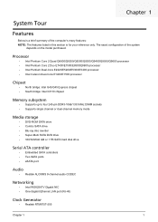
The exact configuration of the computer's many features: NOTE: The features listed in this section is for your reference only. Processor • Intel Pentium Core 2 Quad Q6600/Q8200/Q8300/Q9300/Q9400/Q9550/Q9650 processor • Intel Pentium Core 2 Duo E7400/E7500/E8500/E8600 processor • Intel Pentium Dual-Core E2220/E5200/E5300/E5400 processor • Intel Celeron Dual-Core E1400/E1500 processor Chipset • North bridge: Intel G43/G45 Express chipset • South bridge: Intel ICH10 chipset Memory subsystem • Supports up to four 240-pin DDR3-1066/1333 MHz DIMM sockets ...
The exact configuration of the computer's many features: NOTE: The features listed in this section is for your reference only. Processor • Intel Pentium Core 2 Quad Q6600/Q8200/Q8300/Q9300/Q9400/Q9550/Q9650 processor • Intel Pentium Core 2 Duo E7400/E7500/E8500/E8600 processor • Intel Pentium Dual-Core E2220/E5200/E5300/E5400 processor • Intel Celeron Dual-Core E1400/E1500 processor Chipset • North bridge: Intel G43/G45 Express chipset • South bridge: Intel ICH10 chipset Memory subsystem • Supports up to four 240-pin DDR3-1066/1333 MHz DIMM sockets ...

Service Guide
Page 10
...; Genuine Windows Vista® Ultimate (32/64-bit) • Genuine Windows Vista Home Premium (32/64-bit) • Windows 7 • Applications • Acer Empowering Technology (Acer eRecovery Management) • Acer Arcade Live • McAfee Internet Security Suite 2009 Trial version • Nero 9 System BIOS • SPI Flash ROM 16 MB Power supply •...
...; Genuine Windows Vista® Ultimate (32/64-bit) • Genuine Windows Vista Home Premium (32/64-bit) • Windows 7 • Applications • Acer Empowering Technology (Acer eRecovery Management) • Acer Arcade Live • McAfee Internet Security Suite 2009 Trial version • Nero 9 System BIOS • SPI Flash ROM 16 MB Power supply •...

Service Guide
Page 11
Dimension and weight • Dimension (DxWxH) • X3300: 265 x 100 x 362 mm (with bezel) • X5300: 265 x 100 x 397 mm (with bezel) • Weight (estimate): 5.6 kg (MVB SKU) Chapter 1 3
Dimension and weight • Dimension (DxWxH) • X3300: 265 x 100 x 362 mm (with bezel) • X5300: 265 x 100 x 397 mm (with bezel) • Weight (estimate): 5.6 kg (MVB SKU) Chapter 1 3

Service Guide
Page 12
System Components This section is a virtual tour of the system's interior and exterior components. Front Panel 1 2 3 10 4 9 5 8 6 7 4 Chapter 1
System Components This section is a virtual tour of the system's interior and exterior components. Front Panel 1 2 3 10 4 9 5 8 6 7 4 Chapter 1
Service Guide
Page 13
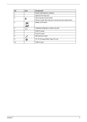
No. Icon Component 1 Power button/power indicator 2 Optical drive bay door 3 Drive bay door eject button Press to open drive bay door and access the optical drive. 4 Media card reader 5 Headphone/Speaker-out/line-out jack 6 USB 2.0 ports 7 Front IO cover 8 Microphone-in jack 9 CF I/II (CompactFlash Type I/II) slot 10 USB 2.0 port Chapter 1 5
No. Icon Component 1 Power button/power indicator 2 Optical drive bay door 3 Drive bay door eject button Press to open drive bay door and access the optical drive. 4 Media card reader 5 Headphone/Speaker-out/line-out jack 6 USB 2.0 ports 7 Front IO cover 8 Microphone-in jack 9 CF I/II (CompactFlash Type I/II) slot 10 USB 2.0 port Chapter 1 5
Service Guide
Page 14
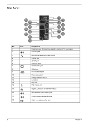
Rear Panel No. Icon 1 2 3 4 5 6 7 8 9 10 11 12 13 14 15 16 17 18 Component Expansion slot (Photo shows graphics card and TV tuner card) Line-out jack Microphone/speaker-out/line-in jack S/PDIF port eSATA port USB 2.0 ports VGA/monitor port HDMI port PS2 keyboard port Power connector Voltage selector switch Lock slot Key hole PS2 mouse port Gigabit LAN port (10/100/1000 Mbps) Rear speaker/surround out jack Center speaker/subwoofer jack Audio in or side speaker jack 6 Chapter 1
Rear Panel No. Icon 1 2 3 4 5 6 7 8 9 10 11 12 13 14 15 16 17 18 Component Expansion slot (Photo shows graphics card and TV tuner card) Line-out jack Microphone/speaker-out/line-in jack S/PDIF port eSATA port USB 2.0 ports VGA/monitor port HDMI port PS2 keyboard port Power connector Voltage selector switch Lock slot Key hole PS2 mouse port Gigabit LAN port (10/100/1000 Mbps) Rear speaker/surround out jack Center speaker/subwoofer jack Audio in or side speaker jack 6 Chapter 1

Service Guide
Page 15
Internal Components No. Component 1 HDD drive 2 Optical drive 3 Expansion cards 4 Mainboard 5 Heat sink fan assembly 6 Power supply Chapter 1 7
Internal Components No. Component 1 HDD drive 2 Optical drive 3 Expansion cards 4 Mainboard 5 Heat sink fan assembly 6 Power supply Chapter 1 7
Service Guide
Page 16
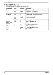
Green LED status On Blinking Off On Blinking Flashing Description The system has AC power and is powered on . System is rebuilding data. HDD is in standby mode. The system is installed and functioning correctly. Ongoing HDD activity. LED indicator Power HDD activity LAN port network speed LED (left) LAN port network connection LED (right) Color Green Green - On On On Off On Blinking Off HDD failure GbE link network access 100 Mbps link network access 10 Mbps link network access Active network link Ongoing network data activity Off-line network 8 Chapter 1 Green Green...
Green LED status On Blinking Off On Blinking Flashing Description The system has AC power and is powered on . System is rebuilding data. HDD is in standby mode. The system is installed and functioning correctly. Ongoing HDD activity. LED indicator Power HDD activity LAN port network speed LED (left) LAN port network connection LED (right) Color Green Green - On On On Off On Blinking Off HDD failure GbE link network access 100 Mbps link network access 10 Mbps link network access Active network link Ongoing network data activity Off-line network 8 Chapter 1 Green Green...

Service Guide
Page 17
Chapter 2 System Utilities CMOS Setup Utility CMOS setup is a hardware configuration program built into the system ROM, called CMOS RAM. In this guide display default system values. This memory area is detected by the system and you close the Setup. Before you run the CMOS Setup Utility, make changes to run this utility under the following conditions. • When changing the system configuration settings • When redefining the communication ports to prevent any conflicts • When modifying the power management configuration • When changing the password or ...
Chapter 2 System Utilities CMOS Setup Utility CMOS setup is a hardware configuration program built into the system ROM, called CMOS RAM. In this guide display default system values. This memory area is detected by the system and you close the Setup. Before you run the CMOS Setup Utility, make changes to run this utility under the following conditions. • When changing the system configuration settings • When redefining the communication ports to prevent any conflicts • When modifying the power management configuration • When changing the password or ...

Service Guide
Page 18
Entering CMOS setup 1. During POST, press Delete. Navigating Through the Setup Utility Use the following keys to the field you want. • PgUp and PgDn keys - Move the cursor to move between selections on , close the utility. 10 Chapter 2 q On a submenu screen, the previous screen displays. If the computer is user-configurable). Use the left and right arrow keys to move around the Setup utility. • Left and Right arrow keys - Select a value for the currently selected field (only if it is already turned on the menu bar. • Up and Down arrow keys - q When ...
Entering CMOS setup 1. During POST, press Delete. Navigating Through the Setup Utility Use the following keys to the field you want. • PgUp and PgDn keys - Move the cursor to move between selections on , close the utility. 10 Chapter 2 q On a submenu screen, the previous screen displays. If the computer is user-configurable). Use the left and right arrow keys to move around the Setup utility. • Left and Right arrow keys - Select a value for the currently selected field (only if it is already turned on the menu bar. • Up and Down arrow keys - q When ...

Service Guide
Page 19
Setup Utility Menus ► Product Information ► Standard CMOS Features ► Advanced BIOS Features ► Advanced Chipset Features ► Integrated Peripherals ► Power Management Setup CMOS Setup Utility ► PC Health Status ► Frequency/Voltage Control ► BIOS Security Features Load Default Settings Save & Exit Setup Exit Without Saving :Move Enter:Select +/-/:Value F1:General Help F9:Optimized Defaults ESC:Exit F10:Save v02.66 (C)Copyright 1985-2009, American Megatrends, Inc. Chapter 2 11 The Setup Main menu includes the following main setup...
Setup Utility Menus ► Product Information ► Standard CMOS Features ► Advanced BIOS Features ► Advanced Chipset Features ► Integrated Peripherals ► Power Management Setup CMOS Setup Utility ► PC Health Status ► Frequency/Voltage Control ► BIOS Security Features Load Default Settings Save & Exit Setup Exit Without Saving :Move Enter:Select +/-/:Value F1:General Help F9:Optimized Defaults ESC:Exit F10:Save v02.66 (C)Copyright 1985-2009, American Megatrends, Inc. Chapter 2 11 The Setup Main menu includes the following main setup...

Service Guide
Page 20
... installed on the system. CMOS Setup Utility Product Information Processor Type : Intel (R) Core(TM)2 Quad CPU Q9650 Processor Speed :3.00GHz System Memory :990MB Product Name :Aspire X5810 System Serial Number : System BIOS Version :P01-A4 BIOS Release Date :08/17/2009 Asset Tag Number : @ 3.00GHz Help Item Parameter Processor Type Processor...
... installed on the system. CMOS Setup Utility Product Information Processor Type : Intel (R) Core(TM)2 Quad CPU Q9650 Processor Speed :3.00GHz System Memory :990MB Product Name :Aspire X5810 System Serial Number : System BIOS Version :P01-A4 BIOS Release Date :08/17/2009 Asset Tag Number : @ 3.00GHz Help Item Parameter Processor Type Processor...

Service Guide
Page 21
Set the system time following the weekday-month-day-year format. Displays the status of auto detection of the AHCI device. Option All, but keyboard] Help Item Use [ENTER] , [TAB] or [SHIFT-TAB] to configure system Date. Determines whether the system will stop for an error during the POST. Parameter System Date Time (hh:mm:ss) AHCI Port 0/3 Halt on CMOS Setup Utility Standard CMOS Features [Wed 08/05/2009] [18:07:24] [ATAPI CDROM] [Hard Disk] [All, but keyboard No Errors All Errors Chapter 2 13 Standard CMOS Features System Date Time (hh:mm:ss) ► AHCI Port 0 ► ...
Set the system time following the weekday-month-day-year format. Displays the status of auto detection of the AHCI device. Option All, but keyboard] Help Item Use [ENTER] , [TAB] or [SHIFT-TAB] to configure system Date. Determines whether the system will stop for an error during the POST. Parameter System Date Time (hh:mm:ss) AHCI Port 0/3 Halt on CMOS Setup Utility Standard CMOS Features [Wed 08/05/2009] [18:07:24] [ATAPI CDROM] [Hard Disk] [All, but keyboard No Errors All Errors Chapter 2 13 Standard CMOS Features System Date Time (hh:mm:ss) ► AHCI Port 0 ► ...