
Aspire E360 User Guide EN
Page 14
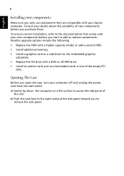
...a) Gently lay down the computer on card, such as a substitute for the embedded graphics subsystem. • Replace the CD drive with your Aspire computer. Possible upgrade options include the following: • Replace the HDD with a higher capacity model, or add a second HDD. • Install additional... memory. • Install a graphics card as a fax/modem card, in one of the unit. Consult your computer off and unplug the power cord...
...a) Gently lay down the computer on card, such as a substitute for the embedded graphics subsystem. • Replace the CD drive with your Aspire computer. Possible upgrade options include the following: • Replace the HDD with a higher capacity model, or add a second HDD. • Install additional... memory. • Install a graphics card as a fax/modem card, in one of the unit. Consult your computer off and unplug the power cord...

Aspire T160/Aspire E360 Service Guide
Page 7
...machine (e.g. If, for repair and service of this printed Service Guide. To better fit local market requirements and enhance product competitiveness, your Acer office may have decided to order FRU parts for whatever reason, a part number change is made, it supports, please read the following ... those given in the FRU list of customer machines. For ACER-AUTHORIZED SERVICE PROVIDERS, your regional office MAY have a DIFFERENT part number code to -date information available on card, modem, or extra memory capability). These LOCALIZED FEATURES will not be covered in this generic...
...machine (e.g. If, for repair and service of this printed Service Guide. To better fit local market requirements and enhance product competitiveness, your Acer office may have decided to order FRU parts for whatever reason, a part number change is made, it supports, please read the following ... those given in the FRU list of customer machines. For ACER-AUTHORIZED SERVICE PROVIDERS, your regional office MAY have a DIFFERENT part number code to -date information available on card, modem, or extra memory capability). These LOCALIZED FEATURES will not be covered in this generic...
Aspire T160/Aspire E360 Service Guide
Page 8
... System LED Definition 4 Block Diagram 5 Main Board Placement 6 Aspire T160 Front Panel 9 Aspire E360 Front Panel 10 AcerPower M6 Front Panel 11 AcerPower M6 Rear Panel 12 Aspire T160/E360 Rear Panel 13 System Peripherals 14 Acer eRecovery 15 Acer disc-to-disc Recovery 17 Hardware Specifications and Configurations 18 Power ...Reader (if equipped 55 Detach the USB Module 57 Detach the CPU Cooler 57 Remove the Memory 58 Remove the System Fan 58 Remove the Main Board 58 Remove the Power Supply 59 Remove the CPU 59 Aspire E360 Desassembly Procedure 59 Open the Computer 60 VIII
... System LED Definition 4 Block Diagram 5 Main Board Placement 6 Aspire T160 Front Panel 9 Aspire E360 Front Panel 10 AcerPower M6 Front Panel 11 AcerPower M6 Rear Panel 12 Aspire T160/E360 Rear Panel 13 System Peripherals 14 Acer eRecovery 15 Acer disc-to-disc Recovery 17 Hardware Specifications and Configurations 18 Power ...Reader (if equipped 55 Detach the USB Module 57 Detach the CPU Cooler 57 Remove the Memory 58 Remove the System Fan 58 Remove the Main Board 58 Remove the Power Supply 59 Remove the CPU 59 Aspire E360 Desassembly Procedure 59 Open the Computer 60 VIII
Aspire T160/Aspire E360 Service Guide
Page 9
Table of Contents Remove the PCI 60 Detach the CPU Cooler 61 Remove the Memory 62 Disconnect the Cables 62 Disassemble the HDD, ODD, FDD and Card Reader 65 Disassemble the USB Module 67 Remove the System Fan 67 Remove ... 97 INTR (Intruder, Case Open Header 97 BAT (Battery 98 How to Erase CMOS 98 Chapter 6 FRU (Field Replaceable Unit) List 99 General Description 99 Aspire E360 Exploded Diagram 100 AcerPower M6 Exploded Diagram 101 Parts 102 IX
Table of Contents Remove the PCI 60 Detach the CPU Cooler 61 Remove the Memory 62 Disconnect the Cables 62 Disassemble the HDD, ODD, FDD and Card Reader 65 Disassemble the USB Module 67 Remove the System Fan 67 Remove ... 97 INTR (Intruder, Case Open Header 97 BAT (Battery 98 How to Erase CMOS 98 Chapter 6 FRU (Field Replaceable Unit) List 99 General Description 99 Aspire E360 Exploded Diagram 100 AcerPower M6 Exploded Diagram 101 Parts 102 IX
Aspire T160/Aspire E360 Service Guide
Page 10
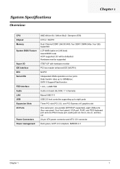
... enhanced IDE (MCP51) NCP51 Independent DMA operation on LAN boot) Award BIOS code ACPI supported; S3 will be defaulted. System Specifications Overview Chapter 1 CPU Chipset Memory System BIOS Feature Super I/O IDE Interface RTC Serial ATA FDD Interface Audio LAN USB Expansion Slots I/O Ports Power Connectors Power management AMD Athlon 64 / Athlon...
... enhanced IDE (MCP51) NCP51 Independent DMA operation on LAN boot) Award BIOS code ACPI supported; S3 will be defaulted. System Specifications Overview Chapter 1 CPU Chipset Memory System BIOS Feature Super I/O IDE Interface RTC Serial ATA FDD Interface Audio LAN USB Expansion Slots I/O Ports Power Connectors Power management AMD Athlon 64 / Athlon...
Aspire T160/Aspire E360 Service Guide
Page 11
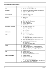
...Two for front daughter board (2*5 pin Intel FPIO) T Data transfer rate support: USB 2.0/1.1 2 Chapter 1 Main Board Specifications Size Processor System Chipset Memory PCI Express / PCI Slots FDD Interface IDE Interface Audio LAN USB (AcerPower M6) Description T Max. 244 mm x 244 mm, Micro ATX ... / Sempron T Socket type: AMD Socket 939 T Socket quantity: one T North bridge: Nvidia C51G T South bridge: MCP51 T Memory type: T DDR T CAS latency, CL = 4 T Socket type: DDR memory slots T Socket quantity: four T Capacity: 256MB to 4GB T Single channel T PCI Express Slot type: x1 / x16 T Quantity...
...Two for front daughter board (2*5 pin Intel FPIO) T Data transfer rate support: USB 2.0/1.1 2 Chapter 1 Main Board Specifications Size Processor System Chipset Memory PCI Express / PCI Slots FDD Interface IDE Interface Audio LAN USB (AcerPower M6) Description T Max. 244 mm x 244 mm, Micro ATX ... / Sempron T Socket type: AMD Socket 939 T Socket quantity: one T North bridge: Nvidia C51G T South bridge: MCP51 T Memory type: T DDR T CAS latency, CL = 4 T Socket type: DDR memory slots T Socket quantity: four T Capacity: 256MB to 4GB T Single channel T PCI Express Slot type: x1 / x16 T Quantity...
Aspire T160/Aspire E360 Service Guide
Page 12
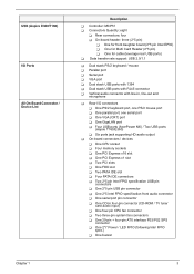
USB (Aspire E360/T160) I/O Ports All On-Board Connector / Device List Description T Controller: MCP51 T Connectors Quantity: eight T Rear connectors: four T On-board header: three (2*5 pin) T One for front ... serial port T One VGA (CRT) port T One GigaLAN port T Four USB ports (AcerPower M6) / Two USB ports (Aspire T160/E360) T Six ports jack supporting HD audio output T On-board connectors / devices T One CPU socket T Four memory sockets T One PCI Express x16 slot T One PCI Express x1 slot T Two PCI slots T One FDD slot...
USB (Aspire E360/T160) I/O Ports All On-Board Connector / Device List Description T Controller: MCP51 T Connectors Quantity: eight T Rear connectors: four T On-board header: three (2*5 pin) T One for front ... serial port T One VGA (CRT) port T One GigaLAN port T Four USB ports (AcerPower M6) / Two USB ports (Aspire T160/E360) T Six ports jack supporting HD audio output T On-board connectors / devices T One CPU socket T Four memory sockets T One PCI Express x16 slot T One PCI Express x1 slot T Two PCI slots T One FDD slot...

Aspire T160/Aspire E360 Service Guide
Page 27
Hardware Specifications and Configurations Major Chips Item System Core Logic Super I/O Controller LAN Controller Memory Controller IDE Controller Audio Controller VGA Controller Keyboard Controller Nvidia C51G MCP51 ITE 8712F Marvell 88E1111 Nvidia C51G MCP51 ALC850 Nvidia C51G ITE 8712F Specification ...
Hardware Specifications and Configurations Major Chips Item System Core Logic Super I/O Controller LAN Controller Memory Controller IDE Controller Audio Controller VGA Controller Keyboard Controller Nvidia C51G MCP51 ITE 8712F Marvell 88E1111 Nvidia C51G MCP51 ALC850 Nvidia C51G ITE 8712F Specification ...

Aspire T160/Aspire E360 Service Guide
Page 28
... VRM 9.0 Typical Voltage 0.8375~1.6v 1.1-1.85 Voltage Power Source 12 Voltage 12 Voltage Maximum Output 101A 70A Cache Memory Item Specification First-Level Cache Configurations Cache function control Enable/Disable by BIOS Setup Second-Level Cache Configurations The information ...Fixed in any combination as long as they match the above specifications. System Memory Item Memory Slot Number Memory Size per Slot Supported Maximum Memory Size Supported Memory Speed Supported memory voltage Support memory module package Support to parity check feature Support to system installed with a ...
... VRM 9.0 Typical Voltage 0.8375~1.6v 1.1-1.85 Voltage Power Source 12 Voltage 12 Voltage Maximum Output 101A 70A Cache Memory Item Specification First-Level Cache Configurations Cache function control Enable/Disable by BIOS Setup Second-Level Cache Configurations The information ...Fixed in any combination as long as they match the above specifications. System Memory Item Memory Slot Number Memory Size per Slot Supported Maximum Memory Size Supported Memory Speed Supported memory voltage Support memory module package Support to parity check feature Support to system installed with a ...
Aspire T160/Aspire E360 Service Guide
Page 38
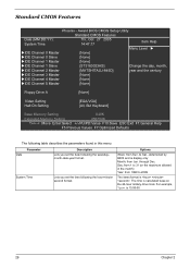
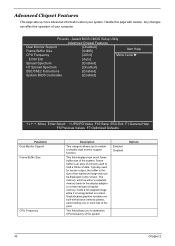
... [None] IDE Channel 4 Master [None] IDE Channel 5 Master [None] Floppy Drive A [None] Video Setting Halt On Setting [EGA/VGA] [All, But Keyboard] Base Memory Setting 640K Extended Memory Setting 456704K :Move Enter:Select +/-/PU/PD:Value F10:Save ESC:Exit F1:General Help F5 Previous Values F7:Optimized Defaults The following table...
... [None] IDE Channel 4 Master [None] IDE Channel 5 Master [None] Floppy Drive A [None] Video Setting Halt On Setting [EGA/VGA] [All, But Keyboard] Base Memory Setting 640K Extended Memory Setting 456704K :Move Enter:Select +/-/PU/PD:Value F10:Save ESC:Exit F1:General Help F5 Previous Values F7:Optimized Defaults The following table...

Aspire T160/Aspire E360 Service Guide
Page 39
... means Enhanced Graphic Adapter/Video Graphic Array. IDE Primary/Secondary Master, Slave IDE Device Setup. The BIOS determines how much extended memory is present during POST (default) None: Select this to automatically detect IDE devices during the POST. Chapter 2 30 Parameter IDE... Primary/Secondary Master, Slave Drive A Video Setting Halt On Base Memory Setting Extended Memory Setting Description Options Allows you . To enter the IDE Master or Slave setup, press [Enter]. The IDE CD-ROM is Enabled...
... means Enhanced Graphic Adapter/Video Graphic Array. IDE Primary/Secondary Master, Slave IDE Device Setup. The BIOS determines how much extended memory is present during POST (default) None: Select this to automatically detect IDE devices during the POST. Chapter 2 30 Parameter IDE... Primary/Secondary Master, Slave Drive A Video Setting Halt On Base Memory Setting Extended Memory Setting Description Options Allows you . To enter the IDE Master or Slave setup, press [Enter]. The IDE CD-ROM is Enabled...
Aspire T160/Aspire E360 Service Guide
Page 41
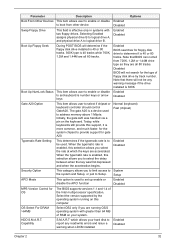
... The BIOS supports versions 1.1 and 1.4 of the Intel multiprocessor specification. Select the version supported by track number. Disabled BIOS will not be used to address memory above 1 Mbyte. The gate A20 is number keys or arrow Disabled keys Gate A20 Option This item allows user to select if chipset or keyboard...
... The BIOS supports versions 1.1 and 1.4 of the Intel multiprocessor specification. Select the version supported by track number. Disabled BIOS will not be used to address memory above 1 Mbyte. The gate A20 is number keys or arrow Disabled keys Gate A20 Option This item allows user to select if chipset or keyboard...
Aspire T160/Aspire E360 Service Guide
Page 42
...Values F7:Optimized Defaults Parameter Dual Monitor Support Frame Buffer Size CPU Frequency Description This category allows you to determine CPU frequency of regular memory, holds a bit mapped image while it is the size of the maximum image that can affect the operation of the system. Typically... used to enable or disable dual monitor support function. Any changes can be displayed on screen. Frame buffer is an area of memory used for screen output, the buffer is being painted on the screen. Enabled Disabled Options 33 Chapter 2 This field displays how much ...
...Values F7:Optimized Defaults Parameter Dual Monitor Support Frame Buffer Size CPU Frequency Description This category allows you to determine CPU frequency of regular memory, holds a bit mapped image while it is the size of the maximum image that can affect the operation of the system. Typically... used to enable or disable dual monitor support function. Any changes can be displayed on screen. Frame buffer is an area of memory used for screen output, the buffer is being painted on the screen. Enabled Disabled Options 33 Chapter 2 This field displays how much ...
Aspire T160/Aspire E360 Service Guide
Page 43
... use those processors. However, if any program writes to process multiple data elements simultaneously. HT is highly recommended that you leave this memory area, a system error may in some cases be able to use of those instruction sets to set will not be outweighed by ...can make use . However, the processor's MMX instruction set some parameters of VGA share memory. This allows SSE- Selecting Enabled allows caching of the system BIOS ROM at the default setting of memory controller. Press [Enter] to enter the setting screen to process large amounts of the processor...
... use those processors. However, if any program writes to process multiple data elements simultaneously. HT is highly recommended that you leave this memory area, a system error may in some cases be able to use of those instruction sets to set will not be outweighed by ...can make use . However, the processor's MMX instruction set some parameters of VGA share memory. This allows SSE- Selecting Enabled allows caching of the system BIOS ROM at the default setting of memory controller. Press [Enter] to enter the setting screen to process large amounts of the processor...

Aspire T160/Aspire E360 Service Guide
Page 47
... LAN controller. Enabled Disabled Enables or disables on board Audio to use the motherboard's onboard LAN controller, you wish to shadow or Base memory. Disabled Chapter 2 38 Enabled Disabled Change the on board lan boot Enabled ROM. This may free up an IRQ for other devices to... auto or Auto disabled. Shadow Base Memory This field enables or disables USB keyboard support function. Onboard Device Setup Phoenix - Disabled Enables or disables onboard LAN controller.If you should...
... LAN controller. Enabled Disabled Enables or disables on board Audio to use the motherboard's onboard LAN controller, you wish to shadow or Base memory. Disabled Chapter 2 38 Enabled Disabled Change the on board lan boot Enabled ROM. This may free up an IRQ for other devices to... auto or Auto disabled. Shadow Base Memory This field enables or disables USB keyboard support function. Onboard Device Setup Phoenix - Disabled Enables or disables onboard LAN controller.If you should...

Aspire T160/Aspire E360 Service Guide
Page 50
...) of power saving for Doze, Standby, and Suspend modes. S3 (STR): Set ACPI suspend type to S3/STR This option allows you to main memory. Max Saving: Maximum power savings. Only Available for ACPI function. User Define: Set each mode individually. Saving: Minimum power savings. Phoenix - S3 ...operating in which power is a low power state. S1(POS): The S1 sleep mode is supplied only to essential components such as main memory and wake-capable devices and all system context. Min. Determines the manner in a manner consistent with your system to enable or disable the...
...) of power saving for Doze, Standby, and Suspend modes. S3 (STR): Set ACPI suspend type to S3/STR This option allows you to main memory. Max Saving: Maximum power savings. Only Available for ACPI function. User Define: Set each mode individually. Saving: Minimum power savings. Phoenix - S3 ...operating in which power is a low power state. S1(POS): The S1 sleep mode is supplied only to essential components such as main memory and wake-capable devices and all system context. Min. Determines the manner in a manner consistent with your system to enable or disable the...
Aspire T160/Aspire E360 Service Guide
Page 56
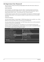
... password, up to abort the selection. You will clear any setting if Supervisor Password is selected, the following message appears at "Security Option" from CMOS memory. Once the password is disabled, the system will be asked to enter password. If you have selected "System" in creating a password.
... password, up to abort the selection. You will clear any setting if Supervisor Password is selected, the following message appears at "Security Option" from CMOS memory. Once the password is disabled, the system will be asked to enter password. If you have selected "System" in creating a password.
Aspire T160/Aspire E360 Service Guide
Page 67
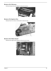
Remove the Memory Push and release those eight screws marked to remove the main board. Remove the Main board Release those two latches to remove the fan. Chapter 3 58 Remove the System Fan Release those four screws on back panel to remove the memory.
Remove the Memory Push and release those eight screws marked to remove the main board. Remove the Main board Release those two latches to remove the fan. Chapter 3 58 Remove the System Fan Release those four screws on back panel to remove the memory.

Aspire T160/Aspire E360 Service Guide
Page 71
2. Release the CPU Cooler latch then remove it. Remove the Memory Press those latches on the left and right sides to pop up the four memories. Disconnect the Cables 1. Chapter 3 62 Disconnect the Audio cable and CD_IN cable.
2. Release the CPU Cooler latch then remove it. Remove the Memory Press those latches on the left and right sides to pop up the four memories. Disconnect the Cables 1. Chapter 3 62 Disconnect the Audio cable and CD_IN cable.

Aspire T160/Aspire E360 Service Guide
Page 79
...Post Checkpoints List: The list may vary accordingly depending on a debug board. If POST discovers errors in numeric co-processor and cache memory subsystem T Direct Memory Access (DMA) controller T Interrupt system T Three programmable timers T ROM subsystem T RAM subsystem T CMOS RAM subsystem and real time ...CMOS R/W functionality Early chipset initialization: T Disable shadow RAM T Disable L2 cache (socket 7 or below) T Program basic chipset registers Detect memory T Auto-detection of L2 cache (socket 7 or below) Expand compressed BIOS code to DRAM Call chipset hook to copy BIOS back to ...
...Post Checkpoints List: The list may vary accordingly depending on a debug board. If POST discovers errors in numeric co-processor and cache memory subsystem T Direct Memory Access (DMA) controller T Interrupt system T Three programmable timers T ROM subsystem T RAM subsystem T CMOS RAM subsystem and real time ...CMOS R/W functionality Early chipset initialization: T Disable shadow RAM T Disable L2 cache (socket 7 or below) T Program basic chipset registers Detect memory T Auto-detection of L2 cache (socket 7 or below) Expand compressed BIOS code to DRAM Call chipset hook to copy BIOS back to ...


