Aspire E360 User Guide EN
Page 14
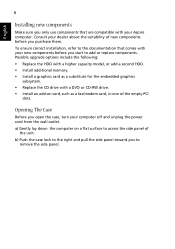
... upgrade options include the following: • Replace the HDD with a higher capacity model, or add a second HDD. • Install additional memory. • Install a graphics card as a substitute for the embedded graphics subsystem. • Replace the CD drive with a DVD or CD-RW drive. • Install an add-on a flat surface to access the side panel of the empty PCI slots. Opening The Case Before you open the case, turn your dealer about the suitability of new components before you start...
... upgrade options include the following: • Replace the HDD with a higher capacity model, or add a second HDD. • Install additional memory. • Install a graphics card as a substitute for the embedded graphics subsystem. • Replace the CD drive with a DVD or CD-RW drive. • Install an add-on a flat surface to access the side panel of the empty PCI slots. Opening The Case Before you open the case, turn your dealer about the suitability of new components before you start...

Aspire E360 User Guide EN
Page 15
... switch located on . Insert the startup disk you can restart your system, refers to the RCD instruction sheet. A: Check the LED located above the power switch. If yes, remove or replace it is lit, check the following: • Is a non-bootable (non-system) diskette in and turned on the rear panel of the computer is set to the correct voltage. • Check if you plugged the power cable...
... switch located on . Insert the startup disk you can restart your system, refers to the RCD instruction sheet. A: Check the LED located above the power switch. If yes, remove or replace it is lit, check the following: • Is a non-bootable (non-system) diskette in and turned on the rear panel of the computer is set to the correct voltage. • Check if you plugged the power cable...

Aspire E360 User Guide EN
Page 16
... disc there may be a problem with the drive. A: Check the following: • Make sure the diskette or hard disk is crossed-out, click on the icon and deselect the Mute option. Q: System cannot write data on . • If headphones, earphones, or external speakers are connected to the line-out jack of your computer, the internal or built-in speakers are using the correct type...
... disc there may be a problem with the drive. A: Check the following: • Make sure the diskette or hard disk is crossed-out, click on the icon and deselect the Mute option. Q: System cannot write data on . • If headphones, earphones, or external speakers are connected to the line-out jack of your computer, the internal or built-in speakers are using the correct type...
Aspire E360 User Guide EN
Page 18
You may also access the Web site (http://global.acer.com/support/index.htm) for information on how and where to contact the service centers available in the "Frequently asked questions" section on page 9 • If your problem is not listed in your screen clean. To clean an optical mouse For users of your computer's internal components Asking for maintenance instructions. Enngglilisshh English English 12...
You may also access the Web site (http://global.acer.com/support/index.htm) for information on how and where to contact the service centers available in the "Frequently asked questions" section on page 9 • If your problem is not listed in your screen clean. To clean an optical mouse For users of your computer's internal components Asking for maintenance instructions. Enngglilisshh English English 12...
Aspire T160/Aspire E360 Service Guide
Page 8
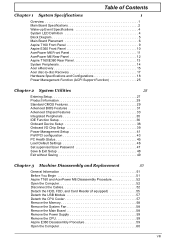
.../E360 Rear Panel 13 System Peripherals 14 Acer eRecovery 15 Acer disc-to-disc Recovery 17 Hardware Specifications and Configurations 18 Power Management Function (ACPI Support Function 25 Chapter 2 System Utilities 26 Entering Setup 27 Product Information 28 Standard CMOS Features 29 Advanced BIOS Features 31 Advanced Chipset Features 33 Integrated Peripherals 35 IDE Function Setup 36 Onboard Device Setup 38 Onboard I/O Chip Setup 39 Power Management Setup 41 PnP/PCI configuration 43 PC Health Status 45 Load Default Settings...
.../E360 Rear Panel 13 System Peripherals 14 Acer eRecovery 15 Acer disc-to-disc Recovery 17 Hardware Specifications and Configurations 18 Power Management Function (ACPI Support Function 25 Chapter 2 System Utilities 26 Entering Setup 27 Product Information 28 Standard CMOS Features 29 Advanced BIOS Features 31 Advanced Chipset Features 33 Integrated Peripherals 35 IDE Function Setup 36 Onboard Device Setup 38 Onboard I/O Chip Setup 39 Power Management Setup 41 PnP/PCI configuration 43 PC Health Status 45 Load Default Settings...
Aspire T160/Aspire E360 Service Guide
Page 9
... Remove the PCI 60 Detach the CPU Cooler 61 Remove the Memory 62 Disconnect the Cables 62 Disassemble the HDD, ODD, FDD and Card Reader 65 Disassemble the USB Module 67 Remove the System Fan 67 Remove the Main Board 67 Remove the Power Supply 68 Separate the CPU from the Main Board 68 Chapter 4 Troubleshooting 69 Power-On Self-Test (POST 69 POST Error Messages List 76 Error Symptoms List 78 Undetermined Problems 83 Chapter 5 Jumper and Connector Information 84 Connectors...
... Remove the PCI 60 Detach the CPU Cooler 61 Remove the Memory 62 Disconnect the Cables 62 Disassemble the HDD, ODD, FDD and Card Reader 65 Disassemble the USB Module 67 Remove the System Fan 67 Remove the Main Board 67 Remove the Power Supply 68 Separate the CPU from the Main Board 68 Chapter 4 Troubleshooting 69 Power-On Self-Test (POST 69 POST Error Messages List 76 Error Symptoms List 78 Undetermined Problems 83 Chapter 5 Jumper and Connector Information 84 Connectors...
Aspire T160/Aspire E360 Service Guide
Page 10
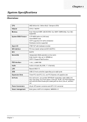
... Independent DMA operation on LAN boot) Award BIOS code ACPI supported; SATA II Support Raid function 1.44/2.88MB FDD Audio on board (ALC850, 7.1 channels) Marvell 88E1111 USB 2.0 host controller supporting up to eight ports Three PCI slot (PCI 2.3), one PCI Express x16 graphics slot One serial port, one parallel (EPP/ECP supported), eight USB ports (four rear panel / four front panel), VGA port, RJ45, one PS/2 keyboard port and one PS/2 mouse port, audio jack six mic-in, line-in, and lineout 24-pin ATX power connector and ATX...
... Independent DMA operation on LAN boot) Award BIOS code ACPI supported; SATA II Support Raid function 1.44/2.88MB FDD Audio on board (ALC850, 7.1 channels) Marvell 88E1111 USB 2.0 host controller supporting up to eight ports Three PCI slot (PCI 2.3), one PCI Express x16 graphics slot One serial port, one parallel (EPP/ECP supported), eight USB ports (four rear panel / four front panel), VGA port, RJ45, one PS/2 keyboard port and one PS/2 mouse port, audio jack six mic-in, line-in, and lineout 24-pin ATX power connector and ATX...
Aspire T160/Aspire E360 Service Guide
Page 11
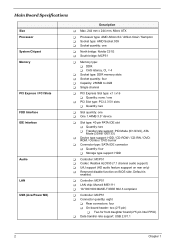
... Slot type: x1 / x16 T Quantity: none / one T PCI Slot type: PCI 2.3 5V slots T Quantity: two T Slot quantity: one T One 1.44MB 3.5" device T Slot type: 40 pin PATA IDE slot T Quantity: two T Transfer rate support: PIO Mode (0/1/2/3/4), ATA Mode (33/66/100/133) T Device type support: HDD / CD-ROW / CD-RW / DVDROM / Combo / DVD burner T Connector type: SATA IDE connector T Quantity: four T Storage type support: HDD T Controller: MCP51 T Codec: Realtek ALC850 (7.1 channel audio support) T UAJ support (HD audio feature suppport on rear only) T Reserved disable function on BIOS...
... Slot type: x1 / x16 T Quantity: none / one T PCI Slot type: PCI 2.3 5V slots T Quantity: two T Slot quantity: one T One 1.44MB 3.5" device T Slot type: 40 pin PATA IDE slot T Quantity: two T Transfer rate support: PIO Mode (0/1/2/3/4), ATA Mode (33/66/100/133) T Device type support: HDD / CD-ROW / CD-RW / DVDROM / Combo / DVD burner T Connector type: SATA IDE connector T Quantity: four T Storage type support: HDD T Controller: MCP51 T Codec: Realtek ALC850 (7.1 channel audio support) T UAJ support (HD audio feature suppport on rear only) T Reserved disable function on BIOS...
Aspire T160/Aspire E360 Service Guide
Page 12
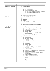
... (Aspire E360/T160) I/O Ports All On-Board Connector / Device List Description T Controller: MCP51 T Connectors Quantity: eight T Rear connectors: four T On-board header: three (2*5 pin) T One for front daughter board (2*5 pin Intel EPIO) T One for Multi Card Reader (2*5 pin) T One for cable (leverage rear USB ports) T Data transfer rate support: USB 2.0/1.1 T Dual stack PS/2 keyboard / mouse T Parallel port T Serial port T VGA port T Dual stack USB ports with 1394 T Dual stack USB ports with RJ45 connector T Vertical audio connector with line-in, line-out and microphone T Rear I/O connectors...
... (Aspire E360/T160) I/O Ports All On-Board Connector / Device List Description T Controller: MCP51 T Connectors Quantity: eight T Rear connectors: four T On-board header: three (2*5 pin) T One for front daughter board (2*5 pin Intel EPIO) T One for Multi Card Reader (2*5 pin) T One for cable (leverage rear USB ports) T Data transfer rate support: USB 2.0/1.1 T Dual stack PS/2 keyboard / mouse T Parallel port T Serial port T VGA port T Dual stack USB ports with 1394 T Dual stack USB ports with RJ45 connector T Vertical audio connector with line-in, line-out and microphone T Rear I/O connectors...
Aspire T160/Aspire E360 Service Guide
Page 24
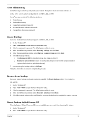
... 2. In the Acer eRecovery window, select Recovery settings and click Next 5. T Backup to optical device to store the backup disc image on CD or DVD (only available on screen to hard drive, CD, or DVD. Create factory default image CD 4. Press + to proceed. After choosing the backup method, click Next. Restore from backup Users can create and save a backup of the following functions: 1. Enter the password to open the Acer eRecovery utility. 3. Press...
... 2. In the Acer eRecovery window, select Recovery settings and click Next 5. T Backup to optical device to store the backup disc image on CD or DVD (only available on screen to hard drive, CD, or DVD. Create factory default image CD 4. Press + to proceed. After choosing the backup method, click Next. Restore from backup Users can create and save a backup of the following functions: 1. Enter the password to open the Acer eRecovery utility. 3. Press...
Aspire T160/Aspire E360 Service Guide
Page 29
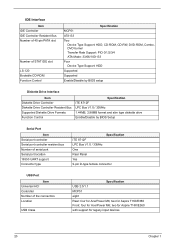
...Device Type Support: HDD Supported Supported Enable/Disable by BIOS setup Diskette Drive Interface Item Diskette Drive Controller Diskette Drive Controller Resident Bus Supported Diskette Drive Formats Function Control Specification ITE 8712F LPC Bus V1.0 / 33MHz 1.44MB, 2.88MB format and slim type diskette drive Enable/Disable by BIOS Setup Serial Port Item Serial port controller Serial port controller resident bus Number of serial port Serial port location 16550 UART support Connector type Specification ITE 8712F LPC Bus V1.0 / 33MHz One Rear Panel Yes 9-pin D-type female connector USB...
...Device Type Support: HDD Supported Supported Enable/Disable by BIOS setup Diskette Drive Interface Item Diskette Drive Controller Diskette Drive Controller Resident Bus Supported Diskette Drive Formats Function Control Specification ITE 8712F LPC Bus V1.0 / 33MHz 1.44MB, 2.88MB format and slim type diskette drive Enable/Disable by BIOS Setup Serial Port Item Serial port controller Serial port controller resident bus Number of serial port Serial port location 16550 UART support Connector type Specification ITE 8712F LPC Bus V1.0 / 33MHz One Rear Panel Yes 9-pin D-type female connector USB...

Aspire T160/Aspire E360 Service Guide
Page 36
... the screen. Entering Setup Power on the computer and the system will appear on the screen, press the key of [Delete] to CMOS and exit setup Abandon all configurations of PCI&PnP ISA resources This setup page is the System auto detect Temperature, voltage, fan and speed Default Settings indicates the value of the system parameters which the system would be in best performance configuration Change, set or disable password.
... the screen. Entering Setup Power on the computer and the system will appear on the screen, press the key of [Delete] to CMOS and exit setup Abandon all configurations of PCI&PnP ISA resources This setup page is the System auto detect Temperature, voltage, fan and speed Default Settings indicates the value of the system parameters which the system would be in best performance configuration Change, set or disable password.

Aspire T160/Aspire E360 Service Guide
Page 39
... Graphic Adapter/Video Graphic Array. Chapter 2 30 This item enables user to the master port of CPU. The IDE CD-ROM is the amount of three methods: Auto: Allows BIOS to set the access mode for faster system start up Manual: User can use one of memory located above 1MB in your computer. You can manually input the correct settings Access Mode: Use this if no IDE devices are : CHS/LBA/Large/Auto (default: Auto) T Cylinder: Number...
... Graphic Adapter/Video Graphic Array. Chapter 2 30 This item enables user to the master port of CPU. The IDE CD-ROM is the amount of three methods: Auto: Allows BIOS to set the access mode for faster system start up Manual: User can use one of memory located above 1MB in your computer. You can manually input the correct settings Access Mode: Use this if no IDE devices are : CHS/LBA/Large/Auto (default: Auto) T Cylinder: Number...
Aspire T160/Aspire E360 Service Guide
Page 42
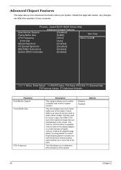
... of your system. Advanced Chipset Features This page sets up more bits of the pixel. Award BIOS CMOS Setup Utility Advanced Chipset Features Dual Monitor Support Frame Buffer Size [Disabled] [64MB] Item Help CPU Frequency [200.0] Menu Level Err94 Enh [Auto] Spread Spectrum [Enabled] HT Spread Spectrum [Disabled] SSE/SSE2 Instructions [Enabled] System BIOS Cacheable [Enabled] :Move Enter:Select +/-/PU/PD:Value F10:Save ESC:Exit F1:General...
... of your system. Advanced Chipset Features This page sets up more bits of the pixel. Award BIOS CMOS Setup Utility Advanced Chipset Features Dual Monitor Support Frame Buffer Size [Disabled] [64MB] Item Help CPU Frequency [200.0] Menu Level Err94 Enh [Auto] Spread Spectrum [Enabled] HT Spread Spectrum [Disabled] SSE/SSE2 Instructions [Enabled] System BIOS Cacheable [Enabled] :Move Enter:Select +/-/PU/PD:Value F10:Save ESC:Exit F1:General...
Aspire T160/Aspire E360 Service Guide
Page 85
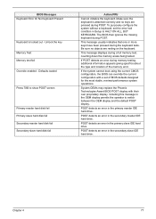
... replace the main board. To diagnose a problem, first find the BIOS error messages in Setup is set to either turn off the system and change the jumper, or enter Setup and change . BIOS Messages BIOS ROM checksum error - defaults loaded CPU at nnnn Display switch is set to skip memory test Floppy disk(s) fail HARD DISK initializing - The CMOS battery is the most likely cause. Determine which setting is installed correctly. Cannot find or initialize the hard drive controller or the drive. Make sure the controller is installed...
... replace the main board. To diagnose a problem, first find the BIOS error messages in Setup is set to either turn off the system and change the jumper, or enter Setup and change . BIOS Messages BIOS ROM checksum error - defaults loaded CPU at nnnn Display switch is set to skip memory test Floppy disk(s) fail HARD DISK initializing - The CMOS battery is the most likely cause. Determine which setting is installed correctly. Cannot find or initialize the hard drive controller or the drive. Make sure the controller is installed...
Aspire T160/Aspire E360 Service Guide
Page 86
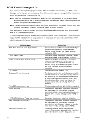
... specifics about the type and location of BIOS defaults designed for the most stable, minimal-performance system operations. POST detects an error in the primary master IDE hard drive. Defaults loaded Press TAB to HALT ON ALL, BUT KEYBOARD. If the system cannot boot using the current CMOS configuration, the BIOS can override the current configuration with their own proprietary display. Unlock the key Memory Test: Memory test fail Override enabled - System OEMs may replace...
... specifics about the type and location of BIOS defaults designed for the most stable, minimal-performance system operations. POST detects an error in the primary master IDE hard drive. Defaults loaded Press TAB to HALT ON ALL, BUT KEYBOARD. If the system cannot boot using the current CMOS configuration, the BIOS can override the current configuration with their own proprietary display. Unlock the key Memory Test: Memory test fail Override enabled - System OEMs may replace...

Aspire T160/Aspire E360 Service Guide
Page 88
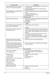
... 2. Diskette drive cable 4. Enter BIOS Setup and Load default settings. 2. Hard disk drive cable. 3. Hard disk drive. 4. Hard disk drive. 4. Main board. With the system power on and its laser beam is clean before diagnosing any hard disk drive problems. (If only one drive is installed, please make sure the drive is connected to light, but works normally. 1. Hard drive LED cable. Software displays a reading CD/DVD error. 1. CD/DVD-ROM may have dirt or foreign material on but system operates normally. 1. Check with a known good disc. 2. CD/DVD-ROM is damaged. CD/DVD-ROM is...
... 2. Diskette drive cable 4. Enter BIOS Setup and Load default settings. 2. Hard disk drive cable. 3. Hard disk drive. 4. Hard disk drive. 4. Main board. With the system power on and its laser beam is clean before diagnosing any hard disk drive problems. (If only one drive is installed, please make sure the drive is connected to light, but works normally. 1. Hard drive LED cable. Software displays a reading CD/DVD error. 1. CD/DVD-ROM may have dirt or foreign material on but system operates normally. 1. Check with a known good disc. 2. CD/DVD-ROM is damaged. CD/DVD-ROM is...
Aspire T160/Aspire E360 Service Guide
Page 89
... 4 Turn up by PCI card is set to Enabled. Ensure the information in BIOS Setup or Power Management is set to Enabled. 2. Modem Modem ring cannot wake up system from speakers. 1. Main board Display problem: - Monitor signal connection/cable. 2. Monitor 3. CD/DVD-ROM drive. Speaker power/connection/cable. In Win 98, ensure the telephone application is configured correctly for your modem and set correctly. 2. Ensure the CD/DVD-ROM driver is set to main board Video and Monitor Video memory test failed. RTC battery. 3. voice from modem adapter card to...
... 4 Turn up by PCI card is set to Enabled. Ensure the information in BIOS Setup or Power Management is set to Enabled. 2. Modem Modem ring cannot wake up system from speakers. 1. Main board Display problem: - Monitor signal connection/cable. 2. Monitor 3. CD/DVD-ROM drive. Speaker power/connection/cable. In Win 98, ensure the telephone application is configured correctly for your modem and set correctly. 2. Ensure the CD/DVD-ROM driver is set to main board Video and Monitor Video memory test failed. RTC battery. 3. voice from modem adapter card to...
Aspire T160/Aspire E360 Service Guide
Page 91
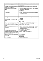
.../Serial Port Execute "Load BIOS Default Settings" in BIOS Setup to the printer service manual. 2. Printer problems. 1. Keyboard Some or all keys on the system. 1. Power switch cable assembly Pressing power switch does not turn on keyboard do not work. 1. Reload software from Windows98 Start menu does not turn off the system. (Only pressing power switch can turn off the system.) 1. Make sure that the LPT# or COM# you test is 1. Printer. 3. Printer cable. 4. Main board. in BIOS Setup. 2. Power switch cable assembly. No system power, or power supply fan...
.../Serial Port Execute "Load BIOS Default Settings" in BIOS Setup to the printer service manual. 2. Printer problems. 1. Keyboard Some or all keys on the system. 1. Power switch cable assembly Pressing power switch does not turn on keyboard do not work. 1. Reload software from Windows98 Start menu does not turn off the system. (Only pressing power switch can turn off the system.) 1. Make sure that the LPT# or COM# you test is 1. Printer. 3. Printer cable. 4. Main board. in BIOS Setup. 2. Power switch cable assembly. No system power, or power supply fan...
Aspire T160/Aspire E360 Service Guide
Page 100
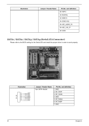
Illustration Jumper / Header Name Pin No. and definition 1: GND 2: SP_TX0P 3: SP_TX0M 4: GND 5: SP_RX0M 6: SP_RX0P 7: GND 91 Chapter 5 Illustration 1 GND 2 SP_TX0P 8 3 SP_TX0M 4 GND 9 5 SP_RX0M 6 SP_RX0P 7 GND Jumper / Header Name 7-pin SATA Header Pin No. and definition 28: WPTJ 30: RDATAJ 32: SIDE1J 34: DSKCHGJ 36: IDE_ADDR_P2 38: IDE_CS3_P* 40: GND SATA1 / SATA2 / SATA3 / SATA4 (Serial ATA Connector) Please refer to the BIOS setting for the Serial ATA and install the proper driver in order to work properly.
Illustration Jumper / Header Name Pin No. and definition 1: GND 2: SP_TX0P 3: SP_TX0M 4: GND 5: SP_RX0M 6: SP_RX0P 7: GND 91 Chapter 5 Illustration 1 GND 2 SP_TX0P 8 3 SP_TX0M 4 GND 9 5 SP_RX0M 6 SP_RX0P 7 GND Jumper / Header Name 7-pin SATA Header Pin No. and definition 28: WPTJ 30: RDATAJ 32: SIDE1J 34: DSKCHGJ 36: IDE_ADDR_P2 38: IDE_CS3_P* 40: GND SATA1 / SATA2 / SATA3 / SATA4 (Serial ATA Connector) Please refer to the BIOS setting for the Serial ATA and install the proper driver in order to work properly.


