Aspire E360 User Guide EN
Page 4
... cabinet has been damaged. Batteries may touch dangerous voltage points or short-out parts that are followed. Do not disassemble or dispose of power supply cord set (provided in fire. Use only the proper type of them away from the wall outlet and refer servicing to normal condition.... operating instructions are covered by a qualified technician to restore the product to qualified service personnel under the following conditions: a When the power cord or plug is a laser product. Replace the battery with the same type as they may explode if not handled properly. English 9.
... cabinet has been damaged. Batteries may touch dangerous voltage points or short-out parts that are followed. Do not disassemble or dispose of power supply cord set (provided in fire. Use only the proper type of them away from the wall outlet and refer servicing to normal condition.... operating instructions are covered by a qualified technician to restore the product to qualified service personnel under the following conditions: a When the power cord or plug is a laser product. Replace the battery with the same type as they may explode if not handled properly. English 9.
Aspire T160/Aspire E360 Service Guide
Page 8
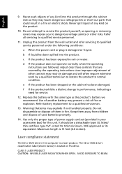
...Definition 4 Block Diagram 5 Main Board Placement 6 Aspire T160 Front Panel 9 Aspire E360 Front Panel 10 AcerPower M6 Front Panel 11 AcerPower M6 Rear Panel 12 Aspire T160/E360 Rear Panel 13 System Peripherals 14 Acer eRecovery 15 Acer disc-to-disc Recovery 17 Hardware Specifications and Configurations 18 Power Management Function (ACPI Support Function 25 Chapter 2... 57 Detach the CPU Cooler 57 Remove the Memory 58 Remove the System Fan 58 Remove the Main Board 58 Remove the Power Supply 59 Remove the CPU 59 Aspire E360 Desassembly Procedure 59 Open the Computer 60 VIII
...Definition 4 Block Diagram 5 Main Board Placement 6 Aspire T160 Front Panel 9 Aspire E360 Front Panel 10 AcerPower M6 Front Panel 11 AcerPower M6 Rear Panel 12 Aspire T160/E360 Rear Panel 13 System Peripherals 14 Acer eRecovery 15 Acer disc-to-disc Recovery 17 Hardware Specifications and Configurations 18 Power Management Function (ACPI Support Function 25 Chapter 2... 57 Detach the CPU Cooler 57 Remove the Memory 58 Remove the System Fan 58 Remove the Main Board 58 Remove the Power Supply 59 Remove the CPU 59 Aspire E360 Desassembly Procedure 59 Open the Computer 60 VIII
Aspire T160/Aspire E360 Service Guide
Page 9
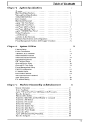
... Reader 65 Disassemble the USB Module 67 Remove the System Fan 67 Remove the Main Board 67 Remove the Power Supply 68 Separate the CPU from the Main Board 68 Chapter 4 Troubleshooting 69 Power-On Self-Test (POST 69 POST Error Messages List 76 Error Symptoms List 78 Undetermined Problems 83 Chapter 5 Jumper... 97 INTR (Intruder, Case Open Header 97 BAT (Battery 98 How to Erase CMOS 98 Chapter 6 FRU (Field Replaceable Unit) List 99 General Description 99 Aspire E360 Exploded Diagram 100 AcerPower M6 Exploded Diagram 101 Parts 102 IX
... Reader 65 Disassemble the USB Module 67 Remove the System Fan 67 Remove the Main Board 67 Remove the Power Supply 68 Separate the CPU from the Main Board 68 Chapter 4 Troubleshooting 69 Power-On Self-Test (POST 69 POST Error Messages List 76 Error Symptoms List 78 Undetermined Problems 83 Chapter 5 Jumper... 97 INTR (Intruder, Case Open Header 97 BAT (Battery 98 How to Erase CMOS 98 Chapter 6 FRU (Field Replaceable Unit) List 99 General Description 99 Aspire E360 Exploded Diagram 100 AcerPower M6 Exploded Diagram 101 Parts 102 IX
Aspire T160/Aspire E360 Service Guide
Page 21
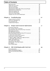
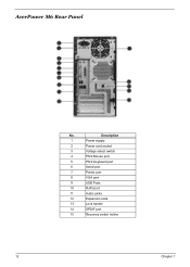
Description 1 Power supply 2 Power cord socket 3 Voltage select switch 4 PS/2 Mouse port 5 PS/2 Keyboard port 6 Serial port 7 Printer port 8 VGA port 9 USB Ports 10 RJ45 port 11 Audio jacks 12 Expansion slots 13 Lock handle 14 SPDIF port 15 Recovery switch holder 12 Chapter 1 AcerPower M6 Rear Panel No.
Description 1 Power supply 2 Power cord socket 3 Voltage select switch 4 PS/2 Mouse port 5 PS/2 Keyboard port 6 Serial port 7 Printer port 8 VGA port 9 USB Ports 10 RJ45 port 11 Audio jacks 12 Expansion slots 13 Lock handle 14 SPDIF port 15 Recovery switch holder 12 Chapter 1 AcerPower M6 Rear Panel No.
Aspire T160/Aspire E360 Service Guide
Page 35
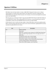
... setting for stable performance Save all the CMOS changes, only for the first time, it is on, pressing the button during the BIOS POST (Power-On Self Test) will take you save changes into CMOS Status Page Setup Menu and Option Page Setup Menu, Exit current page and return to... BIOS needs to be reset to activate certain system features.The CMOS SETUP saves the configuration in the CMOS SRAM on the main board supplies the necessary power to the CMOS SETUP screen. System Utilities Chapter 2 BIOS (Basic Input and Output System) includes a CMOS SETUP utility which allows users to configure...
... setting for stable performance Save all the CMOS changes, only for the first time, it is on, pressing the button during the BIOS POST (Power-On Self Test) will take you save changes into CMOS Status Page Setup Menu and Option Page Setup Menu, Exit current page and return to... BIOS needs to be reset to activate certain system features.The CMOS SETUP saves the configuration in the CMOS SRAM on the main board supplies the necessary power to the CMOS SETUP screen. System Utilities Chapter 2 BIOS (Basic Input and Output System) includes a CMOS SETUP utility which allows users to configure...

Aspire T160/Aspire E360 Service Guide
Page 50
... be used to restore the PC to enable or disable the ACPI function Enabled Disabled This item specifies the power saving modes for SL CPUs. Phoenix - S1(POS): The S1 sleep mode is supplied only to essential components such as main memory and wake-capable devices and all system context. Max Saving...
... be used to restore the PC to enable or disable the ACPI function Enabled Disabled This item specifies the power saving modes for SL CPUs. Phoenix - S1(POS): The S1 sleep mode is supplied only to essential components such as main memory and wake-capable devices and all system context. Max Saving...
Aspire T160/Aspire E360 Service Guide
Page 68
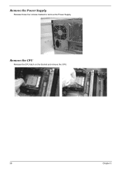
Remove the Power Supply Release those four screws marked to remove the Power Supply. Remove the CPU Release the CPU latch on the Socket and remove the CPU. 59 Chapter 3
Remove the Power Supply Release those four screws marked to remove the Power Supply. Remove the CPU Release the CPU latch on the Socket and remove the CPU. 59 Chapter 3
Aspire T160/Aspire E360 Service Guide
Page 77
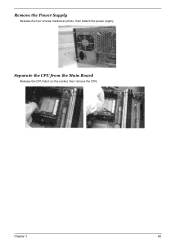
Separate the CPU from the Main Board Release the CPU latch on the socket, then remove the CPU. Chapter 3 68 Remove the Power Supply Release the four screws marked as photo, then detach the power supply.
Separate the CPU from the Main Board Release the CPU latch on the socket, then remove the CPU. Chapter 3 68 Remove the Power Supply Release the four screws marked as photo, then detach the power supply.
Aspire T160/Aspire E360 Service Guide
Page 85
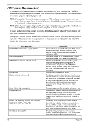
NOTE: When you have deemed it necessary to replace an FRU, and have become corrupt. NOTE: Check all power supply voltages, switch, and jumper settings before you replace the main board. If directed to a check procedure, replace the FRU indicated in Setup. BIOS Messages ... test Floppy disk(s) fail HARD DISK initializing - If you are unable to correct the problem by the change the Video selection. Also check the power supply voltages if you have caused this error. Make sure the controller is no hard drives are installed, be done through the diagnostics program. Make sure...
NOTE: When you have deemed it necessary to replace an FRU, and have become corrupt. NOTE: Check all power supply voltages, switch, and jumper settings before you replace the main board. If directed to a check procedure, replace the FRU indicated in Setup. BIOS Messages ... test Floppy disk(s) fail HARD DISK initializing - If you are unable to correct the problem by the change the Video selection. Also check the power supply voltages if you have caused this error. Make sure the controller is no hard drives are installed, be done through the diagnostics program. Make sure...

Aspire T160/Aspire E360 Service Guide
Page 87
...the FRU indicated in the DIMM sockets properly, then reboot the system. 2. If the reading shows normal, but power supply fan runs. 1. Main board. See "Undetermined Problems". 4. Diskette drive connection/cable 4. Main board Diskette drive does not work . 1. Diskette... / Processor Fan NOTE: Normally, the processor fan should be operative, and the processor clock setting should be +12Vdc. See "Power Management" in Power Management Property of BIOS Setup. 2. Diskette drive connection/cable 4. Main board 78 Chapter 4 Main board and Memory NOTE: Ensure the...
...the FRU indicated in the DIMM sockets properly, then reboot the system. 2. If the reading shows normal, but power supply fan runs. 1. Main board. See "Undetermined Problems". 4. Diskette drive connection/cable 4. Main board Diskette drive does not work . 1. Diskette... / Processor Fan NOTE: Normally, the processor fan should be operative, and the processor clock setting should be +12Vdc. See "Power Management" in Power Management Property of BIOS Setup. 2. Diskette drive connection/cable 4. Main board 78 Chapter 4 Main board and Memory NOTE: Ensure the...
Aspire T160/Aspire E360 Service Guide
Page 91
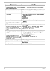
...Default Settings" in BIOS Setup to the printer service manual. 2. Printer. 3. Main board. Keyboard Power Supply Pressing power switch does not turn off system. (Only unplugging the power cord from electrical outlet can turn off the system). 1. Executing software shutdown from Recovery CD. ...4. Keyboard Some or all keys on the system. 1. Load default settings. 2. Power Supply not running. 2. Make sure that the LPT# or COM# you test is 1. Power switch cable assembly Pressing power switch does not turn on keyboard do not work. 1. Main board Other Problems...
...Default Settings" in BIOS Setup to the printer service manual. 2. Printer. 3. Main board. Keyboard Power Supply Pressing power switch does not turn off system. (Only unplugging the power cord from electrical outlet can turn off the system). 1. Executing software shutdown from Recovery CD. ...4. Keyboard Some or all keys on the system. 1. Load default settings. 2. Power Supply not running. 2. Make sure that the LPT# or COM# you test is 1. Power switch cable assembly Pressing power switch does not turn on keyboard do not work. 1. Main board Other Problems...
Aspire T160/Aspire E360 Service Guide
Page 92
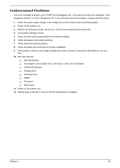
... solve the problem, continue with the following steps: 2. If the jumpers, switches and voltage settings are correct continue with this check: 1. Non-Acer devices T External devices T Any adapter card (modem card, LAN card or video card, if installed) T CD/DVD-ROM drive T Diskette drive ...the following checks, one by one at a time: 10. Check all cables and connectors for proper installation. 9. Check the power supply voltage. Power off the system unit. 3. Power on the system unit. 12. Perform the following , one , until you have isolated the problem FRU. 4. Check all ...
... solve the problem, continue with the following steps: 2. If the jumpers, switches and voltage settings are correct continue with this check: 1. Non-Acer devices T External devices T Any adapter card (modem card, LAN card or video card, if installed) T CD/DVD-ROM drive T Diskette drive ...the following checks, one by one at a time: 10. Check all cables and connectors for proper installation. 9. Check the power supply voltage. Power off the system unit. 3. Power on the system unit. 12. Perform the following , one , until you have isolated the problem FRU. 4. Check all ...
Aspire T160/Aspire E360 Service Guide
Page 94
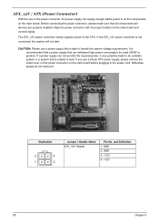
... on the main board and connect tightly. If you use a power supply that is able to the CPU. The ATX_12V power connector mainly supplies power to handle the system voltage requirements. If the ATX_12V power connector is recommended that a power supply that can not provide the required power, it . and Definition 1: GND 2: GND 3: +12V 4: +12V 85 Chapter 5 It is...
... on the main board and connect tightly. If you use a power supply that is able to the CPU. The ATX_12V power connector mainly supplies power to handle the system voltage requirements. If the ATX_12V power connector is recommended that a power supply that can not provide the required power, it . and Definition 1: GND 2: GND 3: +12V 4: +12V 85 Chapter 5 It is...
Aspire T160/Aspire E360 Service Guide
Page 96
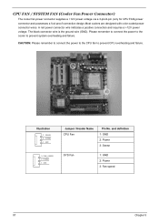
... cooler to prevent CPU overheating and failure. and definition 1: GND 2: Power 3: Sense SYS Fan 1: GND 2: Power 3: Fan speed 87 Chapter 5 Illustration 3 SENSE 3 2 POWER 2 1 1 GND 3 FAN_SPEED 3 2 POWER 2 1 1 GND Jumper / Header Name CPU Fan Pin No. CPU FAN / SYSTEM FAN (Cooler Fan Power Connector) The cooler fan power connector supplies a +12V power voltage via a 3-pin/4-pin (only for CPU FAN...
... cooler to prevent CPU overheating and failure. and definition 1: GND 2: Power 3: Sense SYS Fan 1: GND 2: Power 3: Fan speed 87 Chapter 5 Illustration 3 SENSE 3 2 POWER 2 1 1 GND 3 FAN_SPEED 3 2 POWER 2 1 1 GND Jumper / Header Name CPU Fan Pin No. CPU FAN / SYSTEM FAN (Cooler Fan Power Connector) The cooler fan power connector supplies a +12V power voltage via a 3-pin/4-pin (only for CPU FAN...
Aspire T160/Aspire E360 Service Guide
Page 109
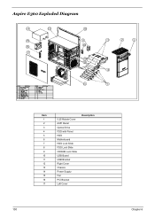
Aspire E360 Exploded Diagram Item 1 2 3 4 5 6 7 8 9 10 11 12 13 14 15 16 17 5.25 Rotate Cover A451 Bezel Optical Drive FDD with Panel HDD Motherboard HDD Lock Slide FDD Lock Slide CDROM Lock Slide USB Board USB Bracket Right Cover Chassis Power Supply Fan PCI Bracket Left Cover Description 100 Chapter 6
Aspire E360 Exploded Diagram Item 1 2 3 4 5 6 7 8 9 10 11 12 13 14 15 16 17 5.25 Rotate Cover A451 Bezel Optical Drive FDD with Panel HDD Motherboard HDD Lock Slide FDD Lock Slide CDROM Lock Slide USB Board USB Bracket Right Cover Chassis Power Supply Fan PCI Bracket Left Cover Description 100 Chapter 6
Aspire T160/Aspire E360 Service Guide
Page 110
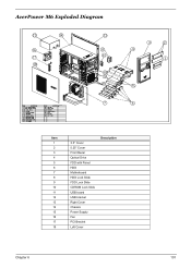
AcerPower M6 Exploded Diagram Item 1 2 3 4 5 6 7 8 9 10 11 12 13 14 15 16 17 18 3.5" Cover 5.25" Cover Front Bezel Optical Drive FDD with Panel HDD Motherboard HDD Lock Slide FDD Lock Slide CDROM Lock Slide USB board USB bracket Right Cover Chassis Power Supply Fan PCI Bracket Left Cover Description Chapter 6 101
AcerPower M6 Exploded Diagram Item 1 2 3 4 5 6 7 8 9 10 11 12 13 14 15 16 17 18 3.5" Cover 5.25" Cover Front Bezel Optical Drive FDD with Panel HDD Motherboard HDD Lock Slide FDD Lock Slide CDROM Lock Slide USB board USB bracket Right Cover Chassis Power Supply Fan PCI Bracket Left Cover Description Chapter 6 101
Aspire T160/Aspire E360 Service Guide
Page 163
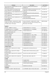
... W/O PFC FSP30060THA(1)(V) POWER SUPPLY 300W W PFC FSP30060THA(1)(V)(PF) POWER SUPPLY 300W W/O PFC LITEON PS6301-08A POWER SUPPLY 300W W/ PFC LITEON PS6301-08AP SCREW CHASSIS SCREW SCREW#6-32UNC SCREW M3X8(VFD BRACKET/UPPER COVER) SCREW #6-32 SPEAKER SPEAKER 2.0 USB M-1118B ACER LOGO HYS64D32300HU-5-C (.11u/Green) HYS64D64320HU-5-C (.11U/GREEN) HYS64D128320HU-5-B NT512D64S8HC0G-5T HYS64D128320HU-5-C (.09u, 512Mb) HYS64D32301HU-5-C (.09u/Green) HYS64D64300HU...
... W/O PFC FSP30060THA(1)(V) POWER SUPPLY 300W W PFC FSP30060THA(1)(V)(PF) POWER SUPPLY 300W W/O PFC LITEON PS6301-08A POWER SUPPLY 300W W/ PFC LITEON PS6301-08AP SCREW CHASSIS SCREW SCREW#6-32UNC SCREW M3X8(VFD BRACKET/UPPER COVER) SCREW #6-32 SPEAKER SPEAKER 2.0 USB M-1118B ACER LOGO HYS64D32300HU-5-C (.11u/Green) HYS64D64320HU-5-C (.11U/GREEN) HYS64D128320HU-5-B NT512D64S8HC0G-5T HYS64D128320HU-5-C (.09u, 512Mb) HYS64D32301HU-5-C (.09u/Green) HYS64D64300HU...


