Quick Start Guide
Page 7
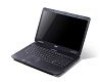
... closed up. The front panel indicators are visible even when the computer cover is charging. 2. Battery indicator1 Indicates the computer's battery status. 1. Touch-sensitive pointing device which functions like and right) the left and right buttons function like a computer mouse. Communication key Enables/disables the computer's ...
... closed up. The front panel indicators are visible even when the computer cover is charging. 2. Battery indicator1 Indicates the computer's battery status. 1. Touch-sensitive pointing device which functions like and right) the left and right buttons function like a computer mouse. Communication key Enables/disables the computer's ...
Quick Start Guide
Page 11
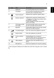
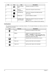
English 9 Base view 1 6 2 5 3 4 # Icon 1 2 3 4 5 6 Item Battery bay Description Houses the computer's battery pack. Note: Do not cover or obstruct the opening of the fan. Environment • Temperature: • Operating: 5 °C to 35 °C...: 20% to stay cool, even after prolonged use. Ventilation slots and cooling fan Enable the computer to 80% Battery lock Locks the battery in position. Battery release latch Releases the battery for removal. Memory compartment Houses the computer's main memory. Hard disk bay Houses the computer's hard disk (secured ...
English 9 Base view 1 6 2 5 3 4 # Icon 1 2 3 4 5 6 Item Battery bay Description Houses the computer's battery pack. Note: Do not cover or obstruct the opening of the fan. Environment • Temperature: • Operating: 5 °C to 35 °C...: 20% to stay cool, even after prolonged use. Ventilation slots and cooling fan Enable the computer to 80% Battery lock Locks the battery in position. Battery release latch Releases the battery for removal. Memory compartment Houses the computer's main memory. Hard disk bay Houses the computer's hard disk (secured ...
Service Guide
Page 7
Table of Contents System Specifications 1 Features 1 Optical Media Drive 2 System Block Diagram 5 Your Acer Notebook tour 6 Front View 6 Closed Front View 7 Left View 7 Right View 9 Bottom View 9 Indicators 10 TouchPad Basics 11 Using the Keyboard 12... 43 Disassembly Requirements 43 Pre-disassembly Instructions 44 Disassembly Process 44 External Module Disassembly Process 45 External Modules Disassembly Flowchart 45 Removing the Battery Pack 46 Removing the SD Dummy Card 47 Removing the Lower Covers 48 Removing the Optical Drive Module 49 Removing the DIMM Modules ...
Table of Contents System Specifications 1 Features 1 Optical Media Drive 2 System Block Diagram 5 Your Acer Notebook tour 6 Front View 6 Closed Front View 7 Left View 7 Right View 9 Bottom View 9 Indicators 10 TouchPad Basics 11 Using the Keyboard 12... 43 Disassembly Requirements 43 Pre-disassembly Instructions 44 Disassembly Process 44 External Module Disassembly Process 45 External Modules Disassembly Flowchart 45 Removing the Battery Pack 46 Removing the SD Dummy Card 47 Removing the Lower Covers 48 Removing the Optical Drive Module 49 Removing the DIMM Modules ...
Service Guide
Page 8
Table of Contents Removing the Mainboard 74 Removing the RTC Battery 75 Removing the Thermal Module 76 Removing the CPU Fan 78 Removing the CPU 79 LCD Module Disassembly Process 80 LCD Module Disassembly Flowchart 80 ... Module 117 Replacing the DIMM Modules 119 Replacing the ODD Module 119 Replacing the Lower Covers 120 Replacing the SD Dummy Card 120 Replacing the Battery 121 Troubleshooting 123 Common Problems 123 Power On Issue 124 No Display Issue 125 Random Loss of BIOS Settings 126 LCD Failure 127 Built-In...
Table of Contents Removing the Mainboard 74 Removing the RTC Battery 75 Removing the Thermal Module 76 Removing the CPU Fan 78 Removing the CPU 79 LCD Module Disassembly Process 80 LCD Module Disassembly Flowchart 80 ... Module 117 Replacing the DIMM Modules 119 Replacing the ODD Module 119 Replacing the Lower Covers 120 Replacing the SD Dummy Card 120 Replacing the Battery 121 Troubleshooting 123 Common Problems 123 Power On Issue 124 No Display Issue 125 Random Loss of BIOS Settings 126 LCD Failure 127 Built-In...
Service Guide
Page 12
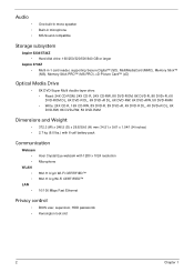
...8226; • • One built-in mono speaker Built-in microphone MS-Sound compatible Storage subsystem Aspire 5334/5734Z • Hard disk drive: 160/250/320/500/640 GB or larger Aspire 5734Z • Multi-in-1 card reader, supporting Secure Digital™ (SD), MultiMediaCard (MMC), Memory...(W) x 246.5 (D) x 26.8/39.6 (H) mm (14.51 x 9.61 x 1.04/1.54 inches) • 2.7 kg (6.0 lbs.) with 6-cell battery pack Communication Webcam • Acer Crystal Eye webcam with 1280 x 1024 resolution • Microphone WLAN • 802.11 b/g/n Wi-Fi CERTIFIED™ • 802.11 b/g Wi-Fi CERTIFIED...
...8226; • • One built-in mono speaker Built-in microphone MS-Sound compatible Storage subsystem Aspire 5334/5734Z • Hard disk drive: 160/250/320/500/640 GB or larger Aspire 5734Z • Multi-in-1 card reader, supporting Secure Digital™ (SD), MultiMediaCard (MMC), Memory...(W) x 246.5 (D) x 26.8/39.6 (H) mm (14.51 x 9.61 x 1.04/1.54 inches) • 2.7 kg (6.0 lbs.) with 6-cell battery pack Communication Webcam • Acer Crystal Eye webcam with 1280 x 1024 resolution • Microphone WLAN • 802.11 b/g/n Wi-Fi CERTIFIED™ • 802.11 b/g Wi-Fi CERTIFIED...
Service Guide
Page 13
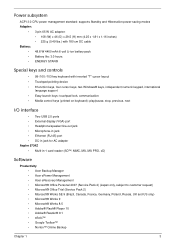
... x 29.5 (H) mm (4.25 x 1.81 x 1.16 inches) • 225 g (0.49 lbs.) with 180 cm DC cable Battery: • 48.8 W 4400 mAh 6-cell Li-ion battery pack • Battery life: 3.0 hours • ENERGY STAR® Special keys and controls • 99-/100-/103-key keyboard with inverted "T" cursor layout ... (RJ-45) port • DC-in jack for AC adapter Aspire 5734Z • Multi-in-1 card reader (SD™, MMC, MS, MS PRO, xD) Software Productivity • Acer Backup Manager • Acer ePower Management • Acer eRecovery Management • Microsoft® Office Personal 2007 (Service Pack...
... x 29.5 (H) mm (4.25 x 1.81 x 1.16 inches) • 225 g (0.49 lbs.) with 180 cm DC cable Battery: • 48.8 W 4400 mAh 6-cell Li-ion battery pack • Battery life: 3.0 hours • ENERGY STAR® Special keys and controls • 99-/100-/103-key keyboard with inverted "T" cursor layout ... (RJ-45) port • DC-in jack for AC adapter Aspire 5734Z • Multi-in-1 card reader (SD™, MMC, MS, MS PRO, xD) Software Productivity • Acer Backup Manager • Acer ePower Management • Acer eRecovery Management • Microsoft® Office Personal 2007 (Service Pack...
Service Guide
Page 14
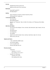
... Skype™ Web links and utilities • Acer Accessory Store (Belgium, France, Germany, Italy, Netherlands, Spain, Sweden, UK only) • Acer Assist • Acer Identity Card • Acer Registration • Acer Updater • eBay® shortcut 2009 (Canada..., France, Germany, Italy, Mexico, Spain, UK, US only) • Netflix shortcut (US only) Optional Items • 1 GB / 2 GB DDR3 soDIMM module • 3-pin 65 W AC adapter • 6-cell Li-ion battery...
... Skype™ Web links and utilities • Acer Accessory Store (Belgium, France, Germany, Italy, Netherlands, Spain, Sweden, UK only) • Acer Assist • Acer Identity Card • Acer Registration • Acer Updater • eBay® shortcut 2009 (Canada..., France, Germany, Italy, Mexico, Spain, UK, US only) • Netflix shortcut (US only) Optional Items • 1 GB / 2 GB DDR3 soDIMM module • 3-pin 65 W AC adapter • 6-cell Li-ion battery...
Service Guide
Page 16
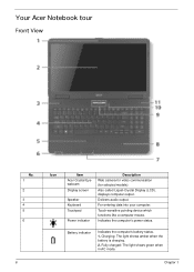
... 1 Delivers audio output. Fully charged: The light shows green when in AC mode. Charging: The light shows amber when the battery is charging. 2. Your Acer Notebook tour Front View No. 1 2 3 4 5 6 6 Icon Item Acer Crystal Eye webcam Display screen Speaker Keyboard Touchpad Power indicator Description Web camera for video communication (for selected models). For...
... 1 Delivers audio output. Fully charged: The light shows green when in AC mode. Charging: The light shows amber when the battery is charging. 2. Your Acer Notebook tour Front View No. 1 2 3 4 5 6 6 Icon Item Acer Crystal Eye webcam Display screen Speaker Keyboard Touchpad Power indicator Description Web camera for video communication (for selected models). For...
Service Guide
Page 19
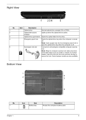
Bottom View 1 6 2 5 3 4 No. 1 Icon Item Battery bay Description Houses the computer's battery pack. Connects to secure the lock. Ejects the optical disk from the drive. Insert the lock into the emergency eject hole to eject the optical ...
Bottom View 1 6 2 5 3 4 No. 1 Icon Item Battery bay Description Houses the computer's battery pack. Connects to secure the lock. Ejects the optical disk from the drive. Insert the lock into the emergency eject hole to eject the optical ...
Service Guide
Page 20
... AC mode. Charging: The light shows amber when the battery is closed. Caps Lock Lights up when Num Lock is activated. Houses the computer's hard disk (secured with screws). The front panel ... when the hard disk drive is activated. 10 Chapter 1 Battery HDD Indicates the computer's battery status. NOTE: 1. Icon Function Power Description Indicates the computer's power status. No. 2 3 4 5 Icon Item Battery release latch Memory compartment Hard disk bay Battery lock Description Releases the battery for removal. Houses the computer's main memory. Num Lock Lights...
... AC mode. Charging: The light shows amber when the battery is closed. Caps Lock Lights up when Num Lock is activated. Houses the computer's hard disk (secured with screws). The front panel ... when the hard disk drive is activated. 10 Chapter 1 Battery HDD Indicates the computer's battery status. NOTE: 1. Icon Function Power Description Indicates the computer's power status. No. 2 3 4 5 Icon Item Battery release latch Memory compartment Hard disk bay Battery lock Description Releases the battery for removal. Houses the computer's main memory. Num Lock Lights...
Service Guide
Page 30
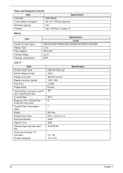
... & model name Battery Type Pack capacity Normal Voltage Package configuration Specification 6 Cell SANYO/SONY/PANASONIC/SAMSUNG/SIMPLO AS2009A Li-ion 4400 mAh 2.2 Ah 3S2P LCD 17" Item Vendor/...
... & model name Battery Type Pack capacity Normal Voltage Package configuration Specification 6 Cell SANYO/SONY/PANASONIC/SAMSUNG/SIMPLO AS2009A Li-ion 4400 mAh 2.2 Ah 3S2P LCD 17" Item Vendor/...
Service Guide
Page 41
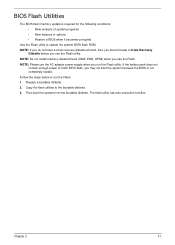
... • Restore a BIOS when it becomes corrupted. Then boot the system from the bootable diskette. Use the Flash utility to the bootable diskette. 3. If the battery pack does not contain enough power to run the Flash utility.
... • Restore a BIOS when it becomes corrupted. Then boot the system from the bootable diskette. Use the Flash utility to the bootable diskette. 3. If the battery pack does not contain enough power to run the Flash utility.
Service Guide
Page 54
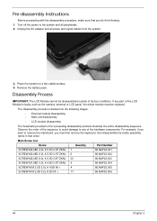
... The flowcharts provided in that you must be disassembled outside of the hardware components. Disassembly Process IMPORTANT: The LCD Module cannot be replaced. Remove the battery pack. Main Screw List Screw Quantity Part Number SCREW M2.48D 4.0L K 5.5D 0.8T ZKNL 1 86.NAF02.001 SCREW M2.48D 6.0L K 5.5D 0.8T ZKNL...
... The flowcharts provided in that you must be disassembled outside of the hardware components. Disassembly Process IMPORTANT: The LCD Module cannot be replaced. Remove the battery pack. Main Screw List Screw Quantity Part Number SCREW M2.48D 4.0L K 5.5D 0.8T ZKNL 1 86.NAF02.001 SCREW M2.48D 6.0L K 5.5D 0.8T ZKNL...
Service Guide
Page 55
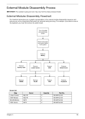
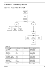
... on the components that need to be removed during servicing. External Module Disassembly Process IMPORTANT: The outside housing and color may vary from system Remove Battery Remove Dummy Card Remove Lower Covers Remove ODD Remove Switch Cover Remove DIMMs Remove WLAN Remove HDD Remove Keyboard Screw List Step Lower Covers ODD...
... on the components that need to be removed during servicing. External Module Disassembly Process IMPORTANT: The outside housing and color may vary from system Remove Battery Remove Dummy Card Remove Lower Covers Remove ODD Remove Switch Cover Remove DIMMs Remove WLAN Remove HDD Remove Keyboard Screw List Step Lower Covers ODD...
Service Guide
Page 56
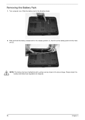
Please detach the battery and follow local regulations for disposal. 46 Chapter 3 Turn computer over. Slide and hold the battery release latch to the release position (1), then lift out the battery pack from the main unit (2). 2 1 NOTE: The battery has been highlighted with a yellow oval as shown in the direction shown. 2. Slide the battery lock in the above image. Removing the Battery Pack 1.
Please detach the battery and follow local regulations for disposal. 46 Chapter 3 Turn computer over. Slide and hold the battery release latch to the release position (1), then lift out the battery pack from the main unit (2). 2 1 NOTE: The battery has been highlighted with a yellow oval as shown in the direction shown. 2. Slide the battery lock in the above image. Removing the Battery Pack 1.
Service Guide
Page 58
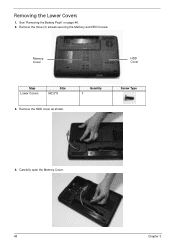
Quantity 3 Screw Type 4. Removing the Lower Covers 1. Memory Cover HDD Cover Step Lower Covers Size M2.5*8 3. Remove the HDD cover as shown. Carefully open the Memory Cover. 48 Chapter 3 See "Removing the Battery Pack" on page 46. 2. Remove the three (3) screws securing the Memory and HDD Covers.
Quantity 3 Screw Type 4. Removing the Lower Covers 1. Memory Cover HDD Cover Step Lower Covers Size M2.5*8 3. Remove the HDD cover as shown. Carefully open the Memory Cover. 48 Chapter 3 See "Removing the Battery Pack" on page 46. 2. Remove the three (3) screws securing the Memory and HDD Covers.
Service Guide
Page 59
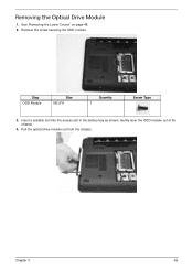
See "Removing the Lower Covers" on page 48. 2. Gently lever the ODD module out of the chassis. 4. Pull the optical drive module out from the chassis. Insert a suitable tool into the access slot in the battery bay as shown. Chapter 3 49 Step ODD Module Size M2.5*8 Quantity 1 Screw Type 3. Remove the screw securing the ODD module. Removing the Optical Drive Module 1.
See "Removing the Lower Covers" on page 48. 2. Gently lever the ODD module out of the chassis. 4. Pull the optical drive module out from the chassis. Insert a suitable tool into the access slot in the battery bay as shown. Chapter 3 49 Step ODD Module Size M2.5*8 Quantity 1 Screw Type 3. Remove the screw securing the ODD module. Removing the Optical Drive Module 1.
Service Guide
Page 67
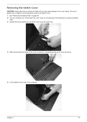
... Switch Cover. 1. Gently insert a thin plastic pry and lift the cover up the cover as shown. 5. Chapter 3 57 Turn the computer over. See "Removing the Battery Pack" on the right side of the computer. Slide the pry along the length of plastic tools or fingers is recommended to remove it. Lift...
... Switch Cover. 1. Gently insert a thin plastic pry and lift the cover up the cover as shown. 5. Chapter 3 57 Turn the computer over. See "Removing the Battery Pack" on the right side of the computer. Slide the pry along the length of plastic tools or fingers is recommended to remove it. Lift...
Service Guide
Page 69
... proceeding Remove LCD Module Upper Cover Remove Upper Cover Remove Power Board Remove Left Speaker Module Remove TouchPad Bracket Lower Cover Remove Mainboard Remove RTC Battery Remove Thermal Module Remove CPU Fan Remove CPU Screw List Step LCD Module LCD Module Upper Cover Upper Cover Power Board Left Speaker Module Right...
... proceeding Remove LCD Module Upper Cover Remove Upper Cover Remove Power Board Remove Left Speaker Module Remove TouchPad Bracket Lower Cover Remove Mainboard Remove RTC Battery Remove Thermal Module Remove CPU Fan Remove CPU Screw List Step LCD Module LCD Module Upper Cover Upper Cover Power Board Left Speaker Module Right...
Service Guide
Page 85
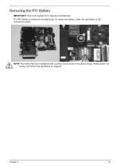
The RTC Battery is soldered to the connections shown. NOTE: The battery has been highlighted with a yellow oval as shown in the above image. To replace the battery, solder the new battery to the Mainboard. Chapter 3 75 Please detach the battery and follow local regulations for disposal of all batteries. Removing the RTC Battery IMPORTANT:Follow local regulations for disposal.
The RTC Battery is soldered to the connections shown. NOTE: The battery has been highlighted with a yellow oval as shown in the above image. To replace the battery, solder the new battery to the Mainboard. Chapter 3 75 Please detach the battery and follow local regulations for disposal of all batteries. Removing the RTC Battery IMPORTANT:Follow local regulations for disposal.


