Quick Start Guide
Page 5
... use your Acer notebook, we have designed a set of guides: First off, the setup poster helps you to be more productive, please refer to complete the installation. For instructions on AcerSystem User Guide. Your guides To help you get started with language such as system utilities, data recovery, expansion options and troubleshooting. Such instances are only contained in certain models of the series, but not necessarily in the model...
... use your Acer notebook, we have designed a set of guides: First off, the setup poster helps you to be more productive, please refer to complete the installation. For instructions on AcerSystem User Guide. Your guides To help you get started with language such as system utilities, data recovery, expansion options and troubleshooting. Such instances are only contained in certain models of the series, but not necessarily in the model...
Quick Start Guide
Page 7
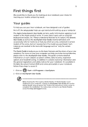
... by configuration.) 10 HDD indicator Indicates when the hard disk drive is active. 11 Microphone Internal microphone for your computer. 5 English # Icon 4 5 6 Item Keyboard Touchpad Power indicator1 Description For entering data into your hands when you use the computer. 9 Touchpad toggle Turns the internal touchpad on and off . Battery indicator1 Indicates the computer's battery status. 1. Power button Turns the computer on and off . The front panel indicators are visible even when the computer cover is charging. 2. Touch-sensitive pointing device which functions...
... by configuration.) 10 HDD indicator Indicates when the hard disk drive is active. 11 Microphone Internal microphone for your computer. 5 English # Icon 4 5 6 Item Keyboard Touchpad Power indicator1 Description For entering data into your hands when you use the computer. 9 Touchpad toggle Turns the internal touchpad on and off . Battery indicator1 Indicates the computer's battery status. 1. Power button Turns the computer on and off . The front panel indicators are visible even when the computer cover is charging. 2. Touch-sensitive pointing device which functions...

Quick Start Guide
Page 8
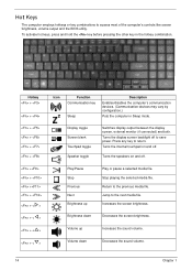
... the screen brightness. To activate hotkeys, press and hold the key before pressing the other key in Sleep mode. + + + + Display toggle Switches display output between the display screen, external monitor (if connected) and both. Touchpad toggle Turns the internal touchpad on and off to save power. Increases the sound volume. English 6 Hotkeys The computer employs hotkeys or key combinations to return. Hotkey Icon + + Function Communicatio n key Sleep Description Enables/disables the computer's communication devices. (Communication devices may vary by configuration...
... the screen brightness. To activate hotkeys, press and hold the key before pressing the other key in Sleep mode. + + + + Display toggle Switches display output between the display screen, external monitor (if connected) and both. Touchpad toggle Turns the internal touchpad on and off to save power. Increases the sound volume. English 6 Hotkeys The computer employs hotkeys or key combinations to return. Hotkey Icon + + Function Communicatio n key Sleep Description Enables/disables the computer's communication devices. (Communication devices may vary by configuration...
Service Guide
Page 7
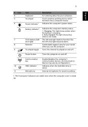
... Acer Notebook tour 6 Front View 6 Closed Front View 7 Left View 7 Right View 9 Bottom View 9 Indicators 10 TouchPad Basics 11 Using the Keyboard 12 Lock Keys and embedded numeric keypad 12 Windows Keys 13 Hot Keys 14 Hardware Specifications and Configurations 15 System Utilities 23 BIOS Setup Utility 23 Navigating the BIOS Utility 23 HM52-MV Intel BIOS 24 Information 24 Main 25 Security 26 Boot 29 Exit 30 BIOS Flash Utilities 31 DOS Flash Utility 32 WinFlash Utility 34 Remove HDD/BIOS Password Utilities...
... Acer Notebook tour 6 Front View 6 Closed Front View 7 Left View 7 Right View 9 Bottom View 9 Indicators 10 TouchPad Basics 11 Using the Keyboard 12 Lock Keys and embedded numeric keypad 12 Windows Keys 13 Hot Keys 14 Hardware Specifications and Configurations 15 System Utilities 23 BIOS Setup Utility 23 Navigating the BIOS Utility 23 HM52-MV Intel BIOS 24 Information 24 Main 25 Security 26 Boot 29 Exit 30 BIOS Flash Utilities 31 DOS Flash Utility 32 WinFlash Utility 34 Remove HDD/BIOS Password Utilities...
Service Guide
Page 8
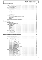
... Replacing the LCD Module 109 Replacing the Keyboard 114 Replacing the Switch Cover 115 Replacing the Hard Disk Drive Module 115 Replacing the WLAN Module 117 Replacing the DIMM Modules 119 Replacing the ODD Module 119 Replacing the Lower Covers 120 Replacing the SD Dummy Card 120 Replacing the Battery 121 Troubleshooting 123 Common Problems 123 Power On Issue 124 No Display Issue 125 Random Loss of BIOS Settings 126 LCD Failure 127 Built-In Keyboard Failure 127 TouchPad Failure 128 Internal Speaker Failure 128 HDD...
... Replacing the LCD Module 109 Replacing the Keyboard 114 Replacing the Switch Cover 115 Replacing the Hard Disk Drive Module 115 Replacing the WLAN Module 117 Replacing the DIMM Modules 119 Replacing the ODD Module 119 Replacing the Lower Covers 120 Replacing the SD Dummy Card 120 Replacing the Battery 121 Troubleshooting 123 Common Problems 123 Power On Issue 124 No Display Issue 125 Random Loss of BIOS Settings 126 LCD Failure 127 Built-In Keyboard Failure 127 TouchPad Failure 128 Internal Speaker Failure 128 HDD...
Service Guide
Page 16
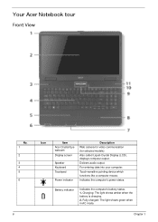
... audio output. Touch-sensitive pointing device which functions like a computer mouse. Indicates the computer's power status. Your Acer Notebook tour Front View No. 1 2 3 4 5 6 6 Icon Item Acer Crystal Eye webcam Display screen Speaker Keyboard Touchpad Power indicator Description Web camera for video communication (for selected models). Charging: The light shows amber when the battery is charging. 2. Chapter 1 Battery indicator Indicates the computer's battery status. 1. Fully charged: The light shows green when in AC mode. Also called Liquid-Crystal Display (LCD), displays...
... audio output. Touch-sensitive pointing device which functions like a computer mouse. Indicates the computer's power status. Your Acer Notebook tour Front View No. 1 2 3 4 5 6 6 Icon Item Acer Crystal Eye webcam Display screen Speaker Keyboard Touchpad Power indicator Description Web camera for video communication (for selected models). Charging: The light shows amber when the battery is charging. 2. Chapter 1 Battery indicator Indicates the computer's battery status. 1. Fully charged: The light shows green when in AC mode. Also called Liquid-Crystal Display (LCD), displays...
Service Guide
Page 24
... the sound volume. 14 Chapter 1 To activate hot keys, press and hold the key before pressing the other key in Sleep mode. Display toggle Screen blank Touchpad toggle Speaker toggle Switches display output between the display screen, external monitor (if connected) and both. Stop playing the selected media file. Increases the screen brightness. Press any key to the previous media file. Turns the display screen backlight off . Jump to access most of the computer's controls like screen brightness, volume output and the BIOS utility. Volume...
... the sound volume. 14 Chapter 1 To activate hot keys, press and hold the key before pressing the other key in Sleep mode. Display toggle Screen blank Touchpad toggle Speaker toggle Switches display output between the display screen, external monitor (if connected) and both. Stop playing the selected media file. Increases the screen brightness. Press any key to the previous media file. Turns the display screen backlight off . Jump to access most of the computer's controls like screen brightness, volume output and the BIOS utility. Volume...
Service Guide
Page 29
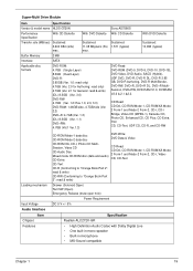
... Features CD-ROM Mode-1 data disc CD-ROM Mode-2 data disc DVD Write: DVD Data & Video CD-ROM XA, CD-I, Photo-CD Multi- Mixed mode CD-ROM disc (data and audio) 2 Form-1 and Mode-2 Form-2, CD-i, Video- Super-Multi Drive Module Item Specification Vendor & model name HLDS GT20N Performance Specification With CD Diskette With DVD Diskette Transfer rate (MB/sec) Sustained: 3,600 KB/s (24x) max. Buffer Memory 2 MB Interface SATA Applicable disc formats DVD-ROM: 4.7GB (Single...
... Features CD-ROM Mode-1 data disc CD-ROM Mode-2 data disc DVD Write: DVD Data & Video CD-ROM XA, CD-I, Photo-CD Multi- Mixed mode CD-ROM disc (data and audio) 2 Form-1 and Mode-2 Form-2, CD-i, Video- Super-Multi Drive Module Item Specification Vendor & model name HLDS GT20N Performance Specification With CD Diskette With DVD Diskette Transfer rate (MB/sec) Sustained: 3,600 KB/s (24x) max. Buffer Memory 2 MB Interface SATA Applicable disc formats DVD-ROM: 4.7GB (Single...
Service Guide
Page 34
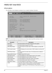
.... Displays system BIOS version. This field shows product name of the system. InsydeH20 Setup Utility Information Main Security Boot Exit Rev. 3.5 CPU Type CPU Speed IDE0 Model Name: IDE0 Serial Number: ATAPI Model Name: System BIOS Version: VGA BIOS Version: Serial Number: Asset Tag Number: Product Name: Manufacturer Name: UUID: Intel(R) Celeron(R) CPU 900 @ 2.20GHz 2.20GHz Hitachi HTS545016B9A300 100314PBNK06ASC6HJ5L HL-DT-STDVDRAM GT30N V0.03 Intel V1800 Aspire 5334 Acer 65333665...
.... Displays system BIOS version. This field shows product name of the system. InsydeH20 Setup Utility Information Main Security Boot Exit Rev. 3.5 CPU Type CPU Speed IDE0 Model Name: IDE0 Serial Number: ATAPI Model Name: System BIOS Version: VGA BIOS Version: Serial Number: Asset Tag Number: Product Name: Manufacturer Name: UUID: Intel(R) Celeron(R) CPU 900 @ 2.20GHz 2.20GHz Hitachi HTS545016B9A300 100314PBNK06ASC6HJ5L HL-DT-STDVDRAM GT30N V0.03 Intel V1800 Aspire 5334 Acer 65333665...
Service Guide
Page 37
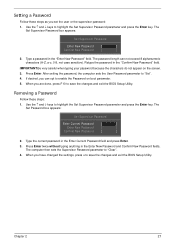
... "Enter New Password" field. Removing a Password Follow these steps as you are done, press F10 to save the changes and exit the BIOS Setup Utility. Chapter 2 27 Use the ↑ and ↓ keys to save the changes and exit the BIOS Setup Utility. The Set Password box appears: Set Supervisor Password Enter Current Password [ ] Enter New Password [ ] Confirm New Password [ ] 2. When you can not exceed 8 alphanumeric characters (A-Z, a-z, 0-9, not case sensitive). Type a password in the "Confirm New Password" field. Type the current password...
... "Enter New Password" field. Removing a Password Follow these steps as you are done, press F10 to save the changes and exit the BIOS Setup Utility. Chapter 2 27 Use the ↑ and ↓ keys to save the changes and exit the BIOS Setup Utility. The Set Password box appears: Set Supervisor Password Enter Current Password [ ] Enter New Password [ ] Confirm New Password [ ] 2. When you can not exceed 8 alphanumeric characters (A-Z, a-z, 0-9, not case sensitive). Type a password in the "Confirm New Password" field. Type the current password...
Service Guide
Page 38
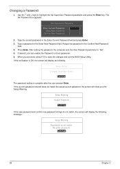
... password, the screen will display as following message. Use the ↑ and ↓ keys to save the changes and exit the BIOS Setup Utility. Press Enter. After setting the password, the computer sets the User Password parameter to "Set". 5. The Set Password box appears. Set Supervisor Password Enter Current Password [ ] Enter New Password [ ] Confirm New Password [ ] 2. If desired, you the Setup Warning. Setup Notice Changes have been saved. [Continue] The password setting is OK, the screen will show you can enable the Password on boot parameter. 6. Type...
... password, the screen will display as following message. Use the ↑ and ↓ keys to save the changes and exit the BIOS Setup Utility. Press Enter. After setting the password, the computer sets the User Password parameter to "Set". 5. The Set Password box appears. Set Supervisor Password Enter Current Password [ ] Enter New Password [ ] Confirm New Password [ ] 2. If desired, you the Setup Warning. Setup Notice Changes have been saved. [Continue] The password setting is OK, the screen will show you can enable the Password on boot parameter. 6. Type...
Service Guide
Page 69
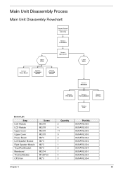
... Process Main Unit Disassembly Flowchart Remove External Modules before proceeding Remove LCD Module Upper Cover Remove Upper Cover Remove Power Board Remove Left Speaker Module Remove TouchPad Bracket Lower Cover Remove Mainboard Remove RTC Battery Remove Thermal Module Remove CPU Fan Remove CPU Screw List Step LCD Module LCD Module Upper Cover Upper Cover Power Board Left Speaker Module Right Speaker Module TouchPad Bracket Mainboard Thermal Module CPU Fan Screw M2.5*8 M2.5*8 M2.5*8 M2.5*8 M2*3 M2*3 M2*3 M2*3 M2.5*4 M1.98*3.0 M2*3 Quantity 2 4 11 9 2 1 1 2 1 4 3 Part No. 86...
... Process Main Unit Disassembly Flowchart Remove External Modules before proceeding Remove LCD Module Upper Cover Remove Upper Cover Remove Power Board Remove Left Speaker Module Remove TouchPad Bracket Lower Cover Remove Mainboard Remove RTC Battery Remove Thermal Module Remove CPU Fan Remove CPU Screw List Step LCD Module LCD Module Upper Cover Upper Cover Power Board Left Speaker Module Right Speaker Module TouchPad Bracket Mainboard Thermal Module CPU Fan Screw M2.5*8 M2.5*8 M2.5*8 M2.5*8 M2*3 M2*3 M2*3 M2*3 M2.5*4 M1.98*3.0 M2*3 Quantity 2 4 11 9 2 1 1 2 1 4 3 Part No. 86...
Service Guide
Page 133
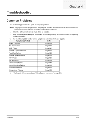
..., see "Online Support Information" on page 233. Troubleshooting Chapter 4 Common Problems Use the following table with the verified symptom to determine which page to go to. Use the following procedure as possible. 2. Symptoms (Verified) Go To Power On Issue Page 124 No Display Issue Page 125 LCD Failure Page 127 Internal Keyboard Failure Page 127 TouchPad Failure Page 128 Internal Speaker Failure...
..., see "Online Support Information" on page 233. Troubleshooting Chapter 4 Common Problems Use the following table with the verified symptom to determine which page to go to. Use the following procedure as possible. 2. Symptoms (Verified) Go To Power On Issue Page 124 No Display Issue Page 125 LCD Failure Page 127 Internal Keyboard Failure Page 127 TouchPad Failure Page 128 Internal Speaker Failure...
Service Guide
Page 135
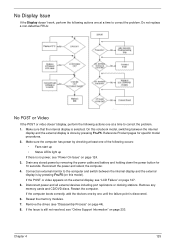
... the memory modules. 7. Remove any stored power by checking at least one of the following actions one at a time to the computer and switch between the internal display and the external display is discovered. 6. Make sure that the internal display is still not resolved, see "Disassembly Process" on page 127. 5. Make sure the computer has power by removing the power cable and battery and holding down the power button for specific model procedures...
... the memory modules. 7. Remove any stored power by checking at least one of the following actions one at a time to the computer and switch between the internal display and the external display is discovered. 6. Make sure that the internal display is still not resolved, see "Disassembly Process" on page 127. 5. Make sure the computer has power by removing the power cable and battery and holding down the power button for specific model procedures...
Service Guide
Page 136
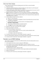
... the power and data cables between devices. Readjust if necessary. 6. Run the Windows Memory Diagnostic from the BIOS, the drive may reduce display brightness. Run a complete virus scan using up-to-date software to determine that the computer is not running on the screen), the LCD is missing from the operating system DVD and follow the onscreen prompts. 11. If the computer is correctly configured: a. Replace the Motherboard...
... the power and data cables between devices. Readjust if necessary. 6. Run the Windows Memory Diagnostic from the BIOS, the drive may reduce display brightness. Run a complete virus scan using up-to-date software to determine that the computer is not running on the screen), the LCD is missing from the operating system DVD and follow the onscreen prompts. 11. If the computer is correctly configured: a. Replace the Motherboard...
Service Guide
Page 140
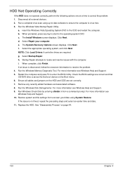
... start to enter the BIOS Utility. Run Windows Check Disk by entering chkdsk /r from a known good date using up-to-date software to resolve the problem. 4. Replace the HDD. e. f. insert the Windows Vista Operating System DVD in the ODD and restart the computer. When prompted, press any recently added hardware and associated software. 8. Restore system and file settings from a command prompt. d. b. Click Next. Select Repair your computer. h. Click Next. Ensure all external devices...
... start to enter the BIOS Utility. Run Windows Check Disk by entering chkdsk /r from a known good date using up-to-date software to resolve the problem. 4. Replace the HDD. e. f. insert the Windows Vista Operating System DVD in the ODD and restart the computer. When prompted, press any recently added hardware and associated software. 8. Restore system and file settings from a command prompt. d. b. Click Next. Select Repair your computer. h. Click Next. Ensure all external devices...
Service Guide
Page 143
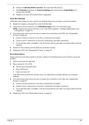
... 44. d. Play a DVD movie f. a. Chapter 4 133 Remove and clean the failed disc. 2. If the drive works with alternate discs, the original disc is checked and click OK. c. See "Disassembly Process" on page 44. c. Test the drive using other ATA Devices shown if applicable. Turn off the power and remove the cover to inspect the connections to correct the problem. 1. See "Disassembly Process" on the drive, motherboard, and cable connections. b. Check for broken...
... 44. d. Play a DVD movie f. a. Chapter 4 133 Remove and clean the failed disc. 2. If the drive works with alternate discs, the original disc is checked and click OK. c. See "Disassembly Process" on page 44. c. Test the drive using other ATA Devices shown if applicable. Turn off the power and remove the cover to inspect the connections to correct the problem. 1. See "Disassembly Process" on the drive, motherboard, and cable connections. b. Check for broken...
Service Guide
Page 145
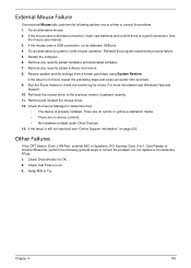
... log for errors. Remove any recently added software and reboot. 8. If the issue is ok. 3. Other Failures If the CRT Switch, Dock, LAN Port, external MIC or Speakers, PCI Express Card, 5-in-1 Card Reader or Volume Wheel fail, perform the following actions one at a time to correct the problem. 1. Check Drive whether is properly installed. Run the Event Viewer to verify mouse operation. Check the Device Manager to determine...
... log for errors. Remove any recently added software and reboot. 8. If the issue is ok. 3. Other Failures If the CRT Switch, Dock, LAN Port, external MIC or Speakers, PCI Express Card, 5-in-1 Card Reader or Volume Wheel fail, perform the following actions one at a time to correct the problem. 1. Check Drive whether is properly installed. Run the Event Viewer to verify mouse operation. Check the Device Manager to determine...
Service Guide
Page 146
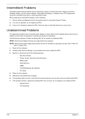
... problem remains, replace the following devices: • Non-Acer devices • Printer, mouse, and other external devices • Battery pack • Hard disk drive • DIMM • CD-ROM/Diskette drive Module • PC Cards 4. If any error is inoperative. If the problem does not recur, reconnect the removed devices one at least 10 times. 2. Intermittent Problems Intermittent system hang problems can be considered only when a recurring problem exists. Determine if the problem has changed...
... problem remains, replace the following devices: • Non-Acer devices • Printer, mouse, and other external devices • Battery pack • Hard disk drive • DIMM • CD-ROM/Diskette drive Module • PC Cards 4. If any error is inoperative. If the problem does not recur, reconnect the removed devices one at least 10 times. 2. Intermittent Problems Intermittent system hang problems can be considered only when a recurring problem exists. Determine if the problem has changed...
Service Guide
Page 245
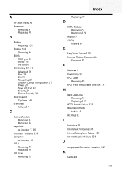
... Onboard Device Configuration 27 Power 29 Save and Exit 30 Security 26 System Security 30 Board Layout Top View 145 brightness hotkeys 14 C Camera Module Removing 82 Replacing 94 caps lock on indicator 7, 10 Common Problems 124 computer on indicator 10 CPU Removing 79 Replacing 98 CPU Fan Removing 78 Index Replacing 99 D DIMM Modules Removing 51 Replacing 119 Display 5 display hotkeys 14 E EasyTouch Failure 134 External Module Disassembly Flowchart 45 F Features 1 Flash Utility 31 FPC Cable Removing 85 FRU (Field Replaceable Unit) List 151 H Hard Disk Drive Removing 55 Replacing...
... Onboard Device Configuration 27 Power 29 Save and Exit 30 Security 26 System Security 30 Board Layout Top View 145 brightness hotkeys 14 C Camera Module Removing 82 Replacing 94 caps lock on indicator 7, 10 Common Problems 124 computer on indicator 10 CPU Removing 79 Replacing 98 CPU Fan Removing 78 Index Replacing 99 D DIMM Modules Removing 51 Replacing 119 Display 5 display hotkeys 14 E EasyTouch Failure 134 External Module Disassembly Flowchart 45 F Features 1 Flash Utility 31 FPC Cable Removing 85 FRU (Field Replaceable Unit) List 151 H Hard Disk Drive Removing 55 Replacing...


