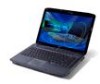
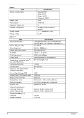
Aspire 4930 / 4930G Service Guide
Page 8
Table of Contents External Modules Disassembly Flowchart 59 Removing the Battery Pack 60 Removing the SD dummy card 61 Removing the ExpressCard dummy card 62 Removing the Lower Covers 63 Removing the DIMM Module 65 Removing ...
Aspire 4930 / 4930G Service Guide
Page 19
Locks the battery in position. Battery release latch Memory compartment Hard disk bay Battery lock Ventilation slots and cooling fan Releases the battery for removal. Houses the computer's hard disk (secured with screws). Bottom View No. 1 2 3 4 5 6 Icon Item Battery bay Description Houses the computer's battery pack. Chapter 1 9 Enable the computer to stay cool, even after prolonged use. Houses the computer's main memory. Note: Do not cover or obstruct the opening of the fan.
Aspire 4930 / 4930G Service Guide
Page 20
Indicators The computer has several easy-to-read status indicators: The front panel indicators are visible even when the computer cover is charging. 2. Charging: The light shows amber when the battery is closed. Fully charged: The light shows green when in AC mode. 10 Chapter 1 Indicates when the hard disk drive is activated. NOTE: 1. Battery HDD Num Lock Caps Lock Indicates the computer's battery status. Lights up when Num Lock is activated. Icon Function Power Description Indicates the computer's power status. Lights up when Caps Lock is active.
Aspire 4930 / 4930G Service Guide
Page 27
... Management hooks up to location-based networks intelligently. • Acer ePower Management optimizes battery usage via customizable power plans. • Acer ePresentation Management connects to a projector and adjusts display settings. • Acer eDataSecurity Management protects data with passwords and encryption. • Acer eLock Management limits access to access frequently used functions and manage your system...
Aspire 4930 / 4930G Service Guide
Page 29
... Management can create, switch between, edit, delete and restore power plans, as default printer settings. Acer ePower Management Acer ePower Management features a straightforward user interface for On Battery and Plugged In modes by clicking "More Power Options". Enter a name for a location to a profile, and automatically switch to the appropriate profile when you to...
Aspire 4930 / 4930G Service Guide
Page 30
...the drop-down list. 2. Switch to the power plan you want your computer to the panel in sleep and hibernate modes. 20 Chapter 1 Battery status For real-time battery life estimates based on /off system components to delete from the drop-down list. 2. To switch between power plans: 1. Click "Apply". ... icon. Click the to save your new settings. 4. You can also turn on current usage, refer to use. 5. Click "Apply" to view estimated battery life in the upper half of the window. Select the power plan you want to delete the active power plan, switch to edit 2. If you...
Aspire 4930 / 4930G Service Guide
Page 46
... 36 Chapter 1 L02, Samsung/LTN141W3-L01 14.1 inches 303.74 x 189.84 mm 1280 x 800 WXGA 0.2373 × 0.2373 mm R.G.B. Battery Item Vendor & model name Battery Type Pack capacity Number of battery cell Package configuration Normal voltage Charge voltage LCD 14.1" Item Vendor/model name Screen Diagonal (mm) Active Area (mm) Display resolution...
Aspire 4930 / 4930G Service Guide
Page 61
... flash ROM. The flash utility has auto-execution function. Copy the flash utilities to finish BIOS flash, you use the Phlash. Chapter 2 51 If the battery pack does not contain enough power to the bootable diskette. 3. Use the Phlash utility to run the Phlash utility. NOTE: If you do not have...
Aspire 4930 / 4930G Service Guide
Page 68
... that you must first remove the keyboard, then disassemble the inside assembly frame in the succeeding disassembly sections illustrate the entire disassembly sequence. Remove the battery pack. Unplug the AC adapter and all peripherals. 2. Place the system on a flat, stable surface. 4. Disassembly Process The disassembly process is divided into the following...
Aspire 4930 / 4930G Service Guide
Page 70
Slide the battery lock/unlock latch to the release position (1), then slide out the battery pack from the main unit (2). 60 Chapter 3 Turn computer over. 2. Slide and hold the battery release latch to the unlock position. 3. Removing the Battery Pack 1.
Aspire 4930 / 4930G Service Guide
Page 73
See "Removing the ExpressCard dummy card" on page 60. 2. Color Black Black Black Torque Chapter 3 63 See "Removing the Battery Pack" on page 62. 4. Step Memory Cover HDD Cover WLAN Cover Size (Quantity) M2.5*8 NL (2) M2*6 NL (2) M2.5*8 NL (1) 5. Carefully open the memory cover. Remove the five screws from the memory, HDD, and WLAN bays. See "Removing the SD dummy card" on page 61. 3. Removing the Lower Covers 1.
Aspire 4930 / 4930G Service Guide
Page 75
Repeat steps for the second DIMM module if present. Push out the release latches on page 60. 2. Chapter 3 65 Remove the DIMM module. 5. Removing the DIMM Module 1. See "Removing the Battery Pack" on both sides of the DIMM socket to release the DIMM module. 4. Remove the Memory Module cover See "Removing the Lower Covers" on page 63. 3.
Aspire 4930 / 4930G Service Guide
Page 76
Disconnect the antenna cables from the WLAN board. 4. Step 1~2 Size (Quantity) M2 x L3 (2) Color Black Torque 1.6 kgf-cm 66 Chapter 3 See "Removing the Battery Pack" on page 63. 3. See "Removing the Lower Covers" on page 60. 2. Move the antenna away and remove the two screws (A) on the WLAN board to release the WLAN board. Removing the WLAN Board Module 1. Remove the WLAN cover.
Aspire 4930 / 4930G Service Guide
Page 78
Remove the HDD cover, See "Removing the Lower Covers" on top of it. 4. Use the mylar tab to slide and lift up the hard disk drive module to the carrier. 68 Chapter 3 Remove the four screws securing the hard disk to remove. NOTE: To prevent damage to device, avoid pressing down on it or placing heavy objects on page 63. 3. See "Removing the Battery Pack" on page 60. 2. Removing the Hard Disk Drive Module 1.
Aspire 4930 / 4930G Service Guide
Page 80
Removing the Optical Drive Module 1. See "Removing the Lower Covers" on page 60. 2. Carefully use a plastic screw driver to release the locking catch. 70 Chapter 3 Remove the screw securing the ODD module. 4. Remove the Memory cover. See "Removing the Battery Pack" on page 63. 3.
Aspire 4930 / 4930G Service Guide
Page 84
Removing the Switch Cover CAUTION: Using tools to remove the Switch Cover may cause damage to expose the Switch Cover. 4. Locate and remove the two securing screws as shown, leftside first. 74 Chapter 3 Step 2 Size (Quantity) M2.5 x 5 (2) Color Black Torque 3. Turn the computer over and open the LCD module fully to the outer casing. See "Removing the Battery Pack" on page 60. 2. It is recommended that only fingers are used to remove the Switch Cover. 1. Lift the Switch Cover as shown.
Aspire 4930 / 4930G Service Guide
Page 86
Removing the Keyboard 1. Push down on page 60.. 2. Lift the keyboard away from the chassis as shown. 76 Chapter 3 See "Removing the Battery Pack" on the two latches securing the keyboard to the upper case. 3.
Aspire 4930 / 4930G Service Guide
Page 92
See "Removing the Lower Covers" on page 78. 6. Removing the LCD Module 1. See "Removing the Antenna" on page 63. 3. See "Removing the Battery Pack" on page 76. 5. Remove the two securing screws from the chassis. 82 Chapter 3 Disconnect the three LCD interface cables from the bottom of the chassis. See "Removing the Keyboard" on page 60. 2. Step 6 Size (Quantity) M2.5*5 NL (2) Color Black Torque 7. See "Removing the WLAN Board Module" on page 66. 4. Turn the computer over.
Aspire 4930 / 4930G Service Guide
Page 94
See "Removing the Battery Pack" on page 62. 4. See "Removing the ExpressCard dummy card" on page 60. 2. See "Removing the WLAN Board Module" on page 63. 5. Step 12 Size (...
Aspire 4930 / 4930G Service Guide
Page 98
See "Removing the ExpressCard dummy card" on page 70. 9. See "Removing the Optical Drive Module" on page 62. 4. See "Removing the Battery Pack" on page 65. 6. Disconnect the Touch Pad cable from the Touch Pad board. 88 Chapter 3 See "Removing the DIMM Module" on page 60. 2. See "...