
AL1906 Service Guide
Page 6
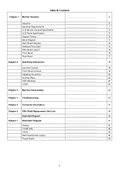
... Hot-Key Menu OSD Message LOGO Chapter 3 Machine Disassembly 6 7 8 9 10 11 12 13 15 16 17 18 18 19 20 23 23 24 25 Chapter 4 Troubleshooting 32 Chapter 5 Connector Information 37 Chapter 6 FRU (Field Replacement Unit) List 38 Exploded Diagram 39 Chapter 7 Schematic Diagram 41 Analog TSUM16AK LVDS Main board power...
... Hot-Key Menu OSD Message LOGO Chapter 3 Machine Disassembly 6 7 8 9 10 11 12 13 15 16 17 18 18 19 20 23 23 24 25 Chapter 4 Troubleshooting 32 Chapter 5 Connector Information 37 Chapter 6 FRU (Field Replacement Unit) List 38 Exploded Diagram 39 Chapter 7 Schematic Diagram 41 Analog TSUM16AK LVDS Main board power...
AL1906 Service Guide
Page 33
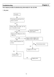
Troubleshooting This chapter provides troubleshooting information for the AL1906: 1. Measure CN701 PIN9/10=5V? NG Check power section OK Replace U701, U702 OK Replace U401 NG Replace X401 32 No power No power Chapter 4 Press power key and look if the picture is normal NG Please reinsert and make sure the AC of 100-240 is normal NG OK Measure U701 PIN2=3.3V, U702 PIN2=3.3V Reinsert or check the power section NG OK X401 oscillate waveforms are normal Measure CN701 PIN5/6=12V?
Troubleshooting This chapter provides troubleshooting information for the AL1906: 1. Measure CN701 PIN9/10=5V? NG Check power section OK Replace U701, U702 OK Replace U401 NG Replace X401 32 No power No power Chapter 4 Press power key and look if the picture is normal NG Please reinsert and make sure the AC of 100-240 is normal NG OK Measure U701 PIN2=3.3V, U702 PIN2=3.3V Reinsert or check the power section NG OK X401 oscillate waveforms are normal Measure CN701 PIN5/6=12V?

