

AL1906 Service Guide
Page 2
Version 1 1.0 Release Date Apr.-21-2006 Revision Initial release 1 Service Guide Version and Revision No.
Version 1 1.0 Release Date Apr.-21-2006 Revision Initial release 1 Service Guide Version and Revision No.
AL1906 Service Guide
Page 3
...following their respective owners. Alerts you to do specific actions relevant to the accomplishment of their purchase, the buyer (and not Acer Incorporated, its distributor, or its dealer) assumes the entire cost of LiteOn Technology Corp. Disclaimer The information in this manual is...that appear on screen. Gives precautionary measures to avoid possible hardware or software problems. Remind you to any particular purpose. ACER AL1906 Service Manual. Printed in this manual: Screen messages NOTE WARNING CAUTION IMPORTANT Denotes actual messages that might result from any ...
...following their respective owners. Alerts you to do specific actions relevant to the accomplishment of their purchase, the buyer (and not Acer Incorporated, its distributor, or its dealer) assumes the entire cost of LiteOn Technology Corp. Disclaimer The information in this manual is...that appear on screen. Gives precautionary measures to avoid possible hardware or software problems. Remind you to any particular purpose. ACER AL1906 Service Manual. Printed in this manual: Screen messages NOTE WARNING CAUTION IMPORTANT Denotes actual messages that might result from any ...
AL1906 Service Guide
Page 4
... meets the ENERGY STAR® guidelines for help. In such cases, please contact your regional Acer office to comply with the limits for Acer's "global" product offering. For ACER-AUTHORIZED SERVICE PROVIDERS, your regional web or channel. As ENERGY STAR® Partner our company...between the equipment and receiver. 3. Notice: 1. The changes or modifications not expressly approved by turning the equipment off and on your Acer office may cause harmful interference to correct such interference. This equipment generates, uses and can be used in accordance with further technical ...
... meets the ENERGY STAR® guidelines for help. In such cases, please contact your regional Acer office to comply with the limits for Acer's "global" product offering. For ACER-AUTHORIZED SERVICE PROVIDERS, your regional web or channel. As ENERGY STAR® Partner our company...between the equipment and receiver. 3. Notice: 1. The changes or modifications not expressly approved by turning the equipment off and on your Acer office may cause harmful interference to correct such interference. This equipment generates, uses and can be used in accordance with further technical ...
AL1906 Service Guide
Page 5
The monitor is provided. Overloading can result in a bookcase or cabinet unless proper ventilation is equipped with a three-pronged grounded plug, a plug with LCD monitor and do not indicate a problem. Never push any object into a grounded power outlet as a missing pixel or a pixel lit all servicing to make sure the flicker disappears. opening or removing covers can injure a person and cause serious damage to service the monitor yourself; The wall socket shall be installed near water, e.g. Special Notes On LCD Monitors The following symptoms are not sure of the type of...
The monitor is provided. Overloading can result in a bookcase or cabinet unless proper ventilation is equipped with a three-pronged grounded plug, a plug with LCD monitor and do not indicate a problem. Never push any object into a grounded power outlet as a missing pixel or a pixel lit all servicing to make sure the flicker disappears. opening or removing covers can injure a person and cause serious damage to service the monitor yourself; The wall socket shall be installed near water, e.g. Special Notes On LCD Monitors The following symptoms are not sure of the type of...
AL1906 Service Guide
Page 6
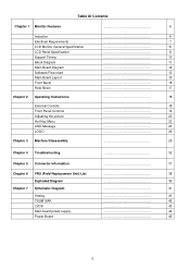
Table Of Contents Chapter 1 Monitor Features 6 Induction Electrical Requirements LCD Monitor General Specification LCD Panel Specification Support Timing Block Diagram Main Board Diagram Software Flow chart Main Board Layout Front Bezel Rear Bezel Chapter 2 Operating Instructions External Controls Front Panel Controls Adjusting the picture Hot-Key Menu OSD Message LOGO Chapter 3 Machine Disassembly 6 7 8 9 10 11 12 13 15 16 17 18 18 19 20 23 23 24 25 Chapter 4 Troubleshooting 32 Chapter...
Table Of Contents Chapter 1 Monitor Features 6 Induction Electrical Requirements LCD Monitor General Specification LCD Panel Specification Support Timing Block Diagram Main Board Diagram Software Flow chart Main Board Layout Front Bezel Rear Bezel Chapter 2 Operating Instructions External Controls Front Panel Controls Adjusting the picture Hot-Key Menu OSD Message LOGO Chapter 3 Machine Disassembly 6 7 8 9 10 11 12 13 15 16 17 18 18 19 20 23 23 24 25 Chapter 4 Troubleshooting 32 Chapter...
AL1906 Service Guide
Page 7
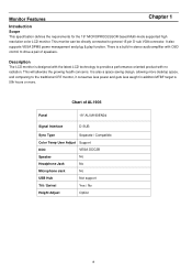
... the requirements for the 19" MICROPROCESSOR based Multi-mode supported high resolution color LCD monitor. This monitor can be directly connected to drive a pair of AL1906 Panel 19" AU M190EN04 Signal Interface D-SUB Sync Type Separate / Compatible Color Temp User Adjust Support DDC VESA DDC2B Speaker No Headphone Jack No Microphone...
... the requirements for the 19" MICROPROCESSOR based Multi-mode supported high resolution color LCD monitor. This monitor can be directly connected to drive a pair of AL1906 Panel 19" AU M190EN04 Signal Interface D-SUB Sync Type Separate / Compatible Color Temp User Adjust Support DDC VESA DDC2B Speaker No Headphone Jack No Microphone...
AL1906 Service Guide
Page 8
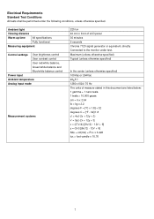
Ambient light Viewing distance Warm up time All specifications Fully functional Measuring equipment Control settings User brightness control User contrast control User red/white balance, Green/white balance and Blue/white balance control Power input Ambient temperature Analog input mode Measurement systems 225 lux 40 cm in x 2.54 lb = kg x 2.2 degrees F = [°C x 1.8] + 32 degrees C = [°F - 32]/1.8 u' = 4x/(-2x + 12y + 3) v' = 9y/(-2x + 12y + 3) x = (27u'/4)/[(9u'/2) - 12v' + 9] y = (3v')/[(9u'/2) - 12v' + 9] Nits = cd/(m2) = Ft-L x 3.426 lux = foot-candle x 10.76 7 Maximum...
Ambient light Viewing distance Warm up time All specifications Fully functional Measuring equipment Control settings User brightness control User contrast control User red/white balance, Green/white balance and Blue/white balance control Power input Ambient temperature Analog input mode Measurement systems 225 lux 40 cm in x 2.54 lb = kg x 2.2 degrees F = [°C x 1.8] + 32 degrees C = [°F - 32]/1.8 u' = 4x/(-2x + 12y + 3) v' = 9y/(-2x + 12y + 3) x = (27u'/4)/[(9u'/2) - 12v' + 9] y = (3v')/[(9u'/2) - 12v' + 9] Nits = cd/(m2) = Ft-L x 3.426 lux = foot-candle x 10.76 7 Maximum...

AL1906 Service Guide
Page 10
LCD Panel Specification LCD Panel Model (AU M190EN04) Display Type active matrix color TFT LCD Resolution 1280x1024 pixels Display Dot 1280x (RGB) x 1024 Display Area 376.32mm(H) x 301.06mm(V) Pixel Pitch 0.294mm(H) x 0.294mm(V) Display Color 16.2M (true) Lamp Frequency 50kHz(Max.) Lamp Current 7.0 mArms (typ.) Weight 2700g (typ.) Optical Specifications Measuring Condition: Ta = 25°C. 9
LCD Panel Specification LCD Panel Model (AU M190EN04) Display Type active matrix color TFT LCD Resolution 1280x1024 pixels Display Dot 1280x (RGB) x 1024 Display Area 376.32mm(H) x 301.06mm(V) Pixel Pitch 0.294mm(H) x 0.294mm(V) Display Color 16.2M (true) Lamp Frequency 50kHz(Max.) Lamp Current 7.0 mArms (typ.) Weight 2700g (typ.) Optical Specifications Measuring Condition: Ta = 25°C. 9
AL1906 Service Guide
Page 11
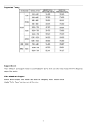
Monitor should display 85Hz refresh rate mode as emergency mode. Supported Timing ٛ. Support Modes There will be 20 total support modes to accommodate the above mode and other video modes within the frequency range of the monitor. 85Hz refresh rate Support Monitor should display " Out of Range" warning menu at this mode. 10
Monitor should display 85Hz refresh rate mode as emergency mode. Supported Timing ٛ. Support Modes There will be 20 total support modes to accommodate the above mode and other video modes within the frequency range of the monitor. 85Hz refresh rate Support Monitor should display " Out of Range" warning menu at this mode. 10

AL1906 Service Guide
Page 12
The Inverter board will contain a main board, a power board, keypad board and audio board which house the flat panel control logic, brightness control logic and DDC. Flat Panel and CCFL backlight Power Board (Inverter, adapter Board) AC-IN 100V-240V Main Board Audio board Keyboard RS232 Connector For white balance adjustment in factory mode HOST Computer Video signal, DDC 11 CCFL Drive. Monitor Block Diagram The LCD MONITOR will drive the backlight of panel.
The Inverter board will contain a main board, a power board, keypad board and audio board which house the flat panel control logic, brightness control logic and DDC. Flat Panel and CCFL backlight Power Board (Inverter, adapter Board) AC-IN 100V-240V Main Board Audio board Keyboard RS232 Connector For white balance adjustment in factory mode HOST Computer Video signal, DDC 11 CCFL Drive. Monitor Block Diagram The LCD MONITOR will drive the backlight of panel.
AL1906 Service Guide
Page 15
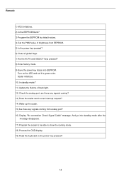
Is the power key pressed? 14 Scalar initializes. 10) In standby mode? 11) Update the lifetime of brightness from analog port? 16) Display "No connection Check Signal Cable" message. Turn on the LED and set it to show the coming from EEPROM. 5) Is the power key pressed? 6) Clear all global flags. 7) Are the AUTO and SELECT keys pressed? 8) Enter factory mode. 9) Save the power key status into standby mode after the message disappears. 17) Program the scalar to be able to green color. And go into EEPROM. Remark: 1) MCU initializes. 2) Is the EEPROM blank? 3) Program the EEPROM by...
Is the power key pressed? 14 Scalar initializes. 10) In standby mode? 11) Update the lifetime of brightness from analog port? 16) Display "No connection Check Signal Cable" message. Turn on the LED and set it to show the coming from EEPROM. 5) Is the power key pressed? 6) Clear all global flags. 7) Are the AUTO and SELECT keys pressed? 8) Enter factory mode. 9) Save the power key status into standby mode after the message disappears. 17) Program the scalar to be able to green color. And go into EEPROM. Remark: 1) MCU initializes. 2) Is the EEPROM blank? 3) Program the EEPROM by...
AL1906 Service Guide
Page 17
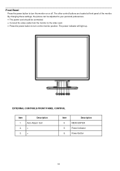
Front Bezel Press the power button to turn the monitor on the monitor position, The power indicator will light up. EXTERNAL CONTROLS FRONT PANEL CONTROL Item 1. 2. 3. Description Auto Adjust / Exit < > Item 4. 5. 6. The other control buttons are located at front panel of the monitor. Description MENU/ENTER Power Indicator Power Button 16 By changing these settings, the picture can be adjusted to your personal preferences. • The power cord should be connected. • Connect the video cable from the monitor to the video card. • Press the power button to turn on or ...
Front Bezel Press the power button to turn the monitor on the monitor position, The power indicator will light up. EXTERNAL CONTROLS FRONT PANEL CONTROL Item 1. 2. 3. Description Auto Adjust / Exit < > Item 4. 5. 6. The other control buttons are located at front panel of the monitor. Description MENU/ENTER Power Indicator Power Button 16 By changing these settings, the picture can be adjusted to your personal preferences. • The power cord should be connected. • Connect the video cable from the monitor to the video card. • Press the power button to turn on or ...

AL1906 Service Guide
Page 18
Connector one end of 15-pin D-SUB cable to the computer's D-DUB port. Turn on your computer before performing the procedure below. 1. Item 1. 2. Rear Bezel Turn off your monitor and computer. Plug the other end of the monitor and connector the other end to the back of the power cord into a nearby outlet. Plug the power cable of your monitor into the PC port. 2. Description Power Cable Signal Cable 17
Connector one end of 15-pin D-SUB cable to the computer's D-DUB port. Turn on your computer before performing the procedure below. 1. Item 1. 2. Rear Bezel Turn off your monitor and computer. Plug the other end of the monitor and connector the other end to the back of the power cord into a nearby outlet. Plug the power cable of your monitor into the PC port. 2. Description Power Cable Signal Cable 17
AL1906 Service Guide
Page 19
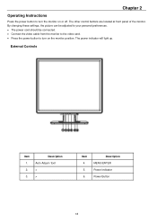
By changing these settings, the picture can be adjusted to your personal preferences. • The power cord should be connected. • Connect the video cable from the monitor to the video card. • Press the power button to turn on or off. Description MENU/ENTER Power Indicator Power Button 18 Chapter 2 Operating Instructions Press the power button to turn the monitor on the monitor position. External Controls Item 1. 2. 3. The other control buttons are located at front panel of the monitor. The power indicator will light up. Description Auto Adjust / Exit < > Item 4....
By changing these settings, the picture can be adjusted to your personal preferences. • The power cord should be connected. • Connect the video cable from the monitor to the video card. • Press the power button to turn on or off. Description MENU/ENTER Power Indicator Power Button 18 Chapter 2 Operating Instructions Press the power button to turn the monitor on the monitor position. External Controls Item 1. 2. 3. The other control buttons are located at front panel of the monitor. The power indicator will light up. Description Auto Adjust / Exit < > Item 4....
AL1906 Service Guide
Page 20
And display the monitor's state. • Power Indicator: Green - NOTES • Do not install the monitor in a location near heat sources such as radiators or air ducts, or in a place subject to direct sunlight, or excessive dust or mechanical vibration or shock. • Save the original shipping carton and packing materials, as it was originally packed at the factory. • To keep the monitor looking new, periodically clean it . 19 Front Panel Control • /Power Button: Press this button to set the HPos, VPos, Clock and Focus. Power on mode. Never use strong solvents ...
And display the monitor's state. • Power Indicator: Green - NOTES • Do not install the monitor in a location near heat sources such as radiators or air ducts, or in a place subject to direct sunlight, or excessive dust or mechanical vibration or shock. • Save the original shipping carton and packing materials, as it was originally packed at the factory. • To keep the monitor looking new, periodically clean it . 19 Front Panel Control • /Power Button: Press this button to set the HPos, VPos, Clock and Focus. Power on mode. Never use strong solvents ...

AL1906 Service Guide
Page 21
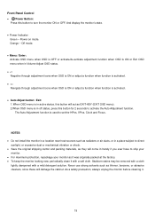
How to change the settings of the current function. 5. Press the MENU-button to select the function that you want to adjust any other function, repeat steps 2-4. Adjusting the Picture a. Press < or >to Adjust a Setting 1. Press to activate the OSD window. 2. Analog-Only Mode 20 To exit and save, select the exit function. If you want to adjust. 4. Press the MENU-button to select the desired function. 3.
How to change the settings of the current function. 5. Press the MENU-button to select the function that you want to adjust any other function, repeat steps 2-4. Adjusting the Picture a. Press < or >to Adjust a Setting 1. Press to activate the OSD window. 2. Analog-Only Mode 20 To exit and save, select the exit function. If you want to adjust. 4. Press the MENU-button to select the desired function. 3.

AL1906 Service Guide
Page 22
User / Red Red Gain from EEPROM. Set OSD display language to Traditional Chinese. Position Adjust the vertical position of the picture. OSD Timeout Adjust the OSD timeout. 21 H. Position Warm N/A Cool N/A Adjust the vertical position of the OSD. User/ Green Green Gain Digital-register. Set OSD display language to English. Set OSD display language to Japanese. Set OSD display language to Spain. H. V. Set OSD display language to Simplified Chinese. Set OSD display language to German. Recall Cool Color Temperature from Digital-register. Set OSD ...
User / Red Red Gain from EEPROM. Set OSD display language to Traditional Chinese. Position Adjust the vertical position of the picture. OSD Timeout Adjust the OSD timeout. 21 H. Position Warm N/A Cool N/A Adjust the vertical position of the OSD. User/ Green Green Gain Digital-register. Set OSD display language to English. Set OSD display language to Japanese. Set OSD display language to Spain. H. V. Set OSD display language to Simplified Chinese. Set OSD display language to German. Recall Cool Color Temperature from Digital-register. Set OSD ...
AL1906 Service Guide
Page 23
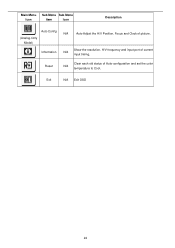
Exit N/A Exit OSD 22 Main Menu Icon Sub Menu Sub Menu Item Icon Description Auto Config (Analog-Only Model) Information N/A Auto Adjust the H/V Position, Focus and Clock of current N/A input timing. Show the resolution, H/V frequency and input port of picture. Reset Clear each old status of Auto-configuration and set the color N/A temperature to Cool.
Exit N/A Exit OSD 22 Main Menu Icon Sub Menu Sub Menu Item Icon Description Auto Config (Analog-Only Model) Information N/A Auto Adjust the H/V Position, Focus and Clock of current N/A input timing. Show the resolution, H/V frequency and input port of picture. Reset Clear each old status of Auto-configuration and set the color N/A temperature to Cool.
AL1906 Service Guide
Page 24
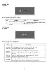
Outline b. The Description For OSD Message Item Description Auto Config When Analog signal input, if User Press Hot-Key "Auto", will be Mute when volume=0 OSD Message a. The Audio will show this message, then enter power saving. 23 This message will Be flying. Input Not Supported Cable Not Connected When the Hsync Frequency, Vsync Frequency or Resolution is No active signal input, will show Please Wait This message, and the monitor do the auto config function. Hot-Key Menu a. Outline b. This message will be Volume Hot-Key Function Volume of The monitor ...
Outline b. The Description For OSD Message Item Description Auto Config When Analog signal input, if User Press Hot-Key "Auto", will be Mute when volume=0 OSD Message a. The Audio will show this message, then enter power saving. 23 This message will Be flying. Input Not Supported Cable Not Connected When the Hsync Frequency, Vsync Frequency or Resolution is No active signal input, will show Please Wait This message, and the monitor do the auto config function. Hot-Key Menu a. Outline b. This message will be Volume Hot-Key Function Volume of The monitor ...
AL1906 Service Guide
Page 25
The DDC2B is a bi-directional data channel based on the level of a minimum No. 18 AWG, type SJT or SVT three conductors flexible cord. After the video input signal is restored, full power is restored and the display is similar to power outlet of its identity and, depending on the I²C protocol. Using The Right Power Cord The accessory power cord for the power cord shall be a video input signal. The voltage rating for the Northern American region is the wallet plug with VESA DDC2B capabilities according to the VESA DDC STANDARD. Logo When the monitor is power on, the LOGO ...
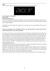
The DDC2B is a bi-directional data channel based on the level of a minimum No. 18 AWG, type SJT or SVT three conductors flexible cord. After the video input signal is restored, full power is restored and the display is similar to power outlet of its identity and, depending on the I²C protocol. Using The Right Power Cord The accessory power cord for the power cord shall be a video input signal. The voltage rating for the Northern American region is the wallet plug with VESA DDC2B capabilities according to the VESA DDC STANDARD. Logo When the monitor is power on, the LOGO ...