
Intel Rapid Storage Guide
Page 1
...without data loss or system downtime. By seamlessly storing copies of data on each drive simultaneously, speeding up data protection can reduce the power consumption of the chipset and Serial ATA (SATA) hard drive. 1 When the failed drive is removed and a replacement hard drive ...hard drive can have additional protection against data loss in a RAID 0 configuration, data can take advantage of enhanced performance and lower power consumption. Intel Rapid Storage Technology can take advantage of faster boot times and data reads. When using one of disk intensive retrieval ...
...without data loss or system downtime. By seamlessly storing copies of data on each drive simultaneously, speeding up data protection can reduce the power consumption of the chipset and Serial ATA (SATA) hard drive. 1 When the failed drive is removed and a replacement hard drive ...hard drive can have additional protection against data loss in a RAID 0 configuration, data can take advantage of enhanced performance and lower power consumption. Intel Rapid Storage Technology can take advantage of faster boot times and data reads. When using one of disk intensive retrieval ...

Intel Rapid Storage Guide
Page 12
Click F2 or Delete to save the BIOS settings and exit the BIOS Setup program. Click F10 to enter the BIOS Setup program after the Power-On-Self-Test (POST) memory test begins. 2. Select 1: Create RAID Volume and press Enter. 3. Press Enter to enable RAID in the system BIOS. 1. When finished ...
Click F2 or Delete to save the BIOS settings and exit the BIOS Setup program. Click F10 to enter the BIOS Setup program after the Power-On-Self-Test (POST) memory test begins. 2. Select 1: Create RAID Volume and press Enter. 3. Press Enter to enable RAID in the system BIOS. 1. When finished ...
RAID Installation Guide
Page 9
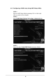
2.4.1 Configuring a RAID array Using UEFI Setup Utility STEP 1: Enter the UEFI Setup Utility by pressing or right after you power on the computer. STEP 3: Select the option Create RAID Volume and press . 9 STEP 2: Enter Intel(R) Rapid Storage Technology in Advanced page.
2.4.1 Configuring a RAID array Using UEFI Setup Utility STEP 1: Enter the UEFI Setup Utility by pressing or right after you power on the computer. STEP 3: Select the option Create RAID Volume and press . 9 STEP 2: Enter Intel(R) Rapid Storage Technology in Advanced page.

Quick Installation Guide
Page 3
.../Bass LINE IN Center: REAR SPK Bottom: Optical SPDIF CHA_FAN3 CHA_FAN2 PCIE_PWR1 TPMS1 7 Top: Center: FRONT Bottom: MIC IN 33 PCIE1 1 Purity SoundTM 2 Z97 Extreme4 PCIE2 32 8 9 CHA_FAN1 10 SATA3_A1 SATA3_A0 1 SATA_PWR_1 11 12 SATA3_3 SATA3_0 PCIE3 13 14 PCIE4 CMOS Battery 31 1 HD_AUDIO1 PCIE5 Intel SATA3_1 SATA3_4 15...1 USB2_3 1 USB4_5 1 SPEAKER1 1 1 PLED1 PLED PWRBTN 1 HDLED RESET PANEL1 Dr. Debug BIOS_SEL1 A B 64Mb BIOS BIOS_B 64Mb BIOS BIOS_A BIOS_B_LED BIOS_A_LED CLRCBTN1 Reset Power 19 30 29 28 27 26 25 24 23 22 21 20 English 1
.../Bass LINE IN Center: REAR SPK Bottom: Optical SPDIF CHA_FAN3 CHA_FAN2 PCIE_PWR1 TPMS1 7 Top: Center: FRONT Bottom: MIC IN 33 PCIE1 1 Purity SoundTM 2 Z97 Extreme4 PCIE2 32 8 9 CHA_FAN1 10 SATA3_A1 SATA3_A0 1 SATA_PWR_1 11 12 SATA3_3 SATA3_0 PCIE3 13 14 PCIE4 CMOS Battery 31 1 HD_AUDIO1 PCIE5 Intel SATA3_1 SATA3_4 15...1 USB2_3 1 USB4_5 1 SPEAKER1 1 1 PLED1 PLED PWRBTN 1 HDLED RESET PANEL1 Dr. Debug BIOS_SEL1 A B 64Mb BIOS BIOS_B 64Mb BIOS BIOS_A BIOS_B_LED BIOS_A_LED CLRCBTN1 Reset Power 19 30 29 28 27 26 25 24 23 22 21 20 English 1
Quick Installation Guide
Page 4
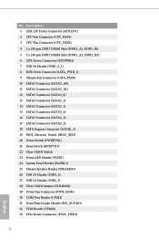
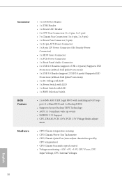
... 3 CPU Fan Connector (CPU_FAN2) 4 2 x 240-pin DDR3 DIMM Slots (DDR3_A1, DDR3_B1) 5 2 x 240-pin DDR3 DIMM Slots (DDR3_A2, DDR3_B2) 6 ATX Power Connector (ATXPWR1) 7 USB 3.0 Header (USB3_0_1) 8 HDD Saver Connector (SATA_PWR_1) 9 Chassis Fan Connector (CHA_FAN1) 10 SATA3 Connector (SATA3_A0) 11 SATA3 Connector (SATA3_A1) ... 17 SATA3 Connector (SATA3_5) 18 SATA Express Connector (SATAE_1) 19 BIOS Selection Switch (BIOS_SEL1) 20 Power Switch (PWRBTN1) 21 Reset Switch (RSTBTN1) 22 Clear CMOS Switch 23 Power LED Header (PLED1) 24 System Panel Header (PANEL1) 25 Chassis Speaker Header (SPEAKER1) 26 USB...
... 3 CPU Fan Connector (CPU_FAN2) 4 2 x 240-pin DDR3 DIMM Slots (DDR3_A1, DDR3_B1) 5 2 x 240-pin DDR3 DIMM Slots (DDR3_A2, DDR3_B2) 6 ATX Power Connector (ATXPWR1) 7 USB 3.0 Header (USB3_0_1) 8 HDD Saver Connector (SATA_PWR_1) 9 Chassis Fan Connector (CHA_FAN1) 10 SATA3 Connector (SATA3_A0) 11 SATA3 Connector (SATA3_A1) ... 17 SATA3 Connector (SATA3_5) 18 SATA Express Connector (SATAE_1) 19 BIOS Selection Switch (BIOS_SEL1) 20 Power Switch (PWRBTN1) 21 Reset Switch (RSTBTN1) 22 Clear CMOS Switch 23 Power LED Header (PLED1) 24 System Panel Header (PANEL1) 25 Chassis Speaker Header (SPEAKER1) 26 USB...
Quick Installation Guide
Page 9
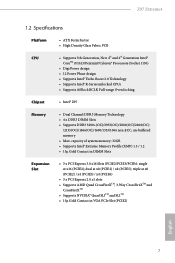
... Intel® Extreme Memory Profile (XMP) 1.3 / 1.2 • 15μ Gold Contact in VGA PCIe Slot (PCIE2) English 7 Z97 Extreme4 1.2 Specifications Platform CPU • ATX Form Factor • High Density Glass Fabric PCB • Supports 5th Generation, New 4th and 4th... Processors (Socket 1150) • Digi Power design • 12 Power Phase design • Supports Intel® Turbo Boost 2.0 Technology • Supports Intel® K-Series unlocked CPUs • Supports ASRock BCLK Full-range Overclocking Chipset • Intel® Z97 Memory • Dual Channel DDR3 Memory ...
... Intel® Extreme Memory Profile (XMP) 1.3 / 1.2 • 15μ Gold Contact in VGA PCIe Slot (PCIE2) English 7 Z97 Extreme4 1.2 Specifications Platform CPU • ATX Form Factor • High Density Glass Fabric PCB • Supports 5th Generation, New 4th and 4th... Processors (Socket 1150) • Digi Power design • 12 Power Phase design • Supports Intel® Turbo Boost 2.0 Technology • Supports Intel® K-Series unlocked CPUs • Supports ASRock BCLK Full-range Overclocking Chipset • Intel® Z97 Memory • Dual Channel DDR3 Memory ...
Quick Installation Guide
Page 12
... • 1 x Front Panel Audio Connector • 2 x USB 2.0 Headers (support 4 USB 2.0 ports) (Supports ESD Protection (ASRock Full Spike Protection)) • 1 x USB 3.0 Header (support 2 USB 3.0 ports) (Supports ESD Protection (ASRock Full Spike Protection)) • 1 x Dr. Debug with LED • 1 x Power Switch with LED • 1 x Reset Switch with LED • 1 x BIOS Selection Switch BIOS Feature •...
... • 1 x Front Panel Audio Connector • 2 x USB 2.0 Headers (support 4 USB 2.0 ports) (Supports ESD Protection (ASRock Full Spike Protection)) • 1 x USB 3.0 Header (support 2 USB 3.0 ports) (Supports ESD Protection (ASRock Full Spike Protection)) • 1 x Dr. Debug with LED • 1 x Power Switch with LED • 1 x Reset Switch with LED • 1 x BIOS Selection Switch BIOS Feature •...
Quick Installation Guide
Page 13
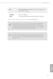
...required) * For detailed product information, please visit our website: http://www.asrock.com Please realize that Windows® cannot use. You can use ASRock XFast RAM to the components and devices of your own risk and expense. Z97 Extreme4 OS • Microsoft® Windows® 8.1 32-bit / 8.1... 64-bit / 8 32-bit / 8 64- bit / 7 32-bit / 7 64-bit Certifications • FCC, CE, WHQL • ErP/EuP ready (ErP/EuP ready power...
...required) * For detailed product information, please visit our website: http://www.asrock.com Please realize that Windows® cannot use. You can use ASRock XFast RAM to the components and devices of your own risk and expense. Z97 Extreme4 OS • Microsoft® Windows® 8.1 32-bit / 8.1... 64-bit / 8 32-bit / 8 64- bit / 7 32-bit / 7 64-bit Certifications • FCC, CE, WHQL • ErP/EuP ready (ErP/EuP ready power...
Quick Installation Guide
Page 14
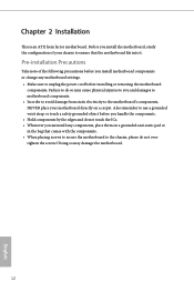
... secure the motherboard to the chassis, please do not touch the ICs. • Whenever you uninstall any motherboard settings. • Make sure to unplug the power cord before you and damages to motherboard components. • In order to avoid damage from static electricity to use a grounded wrist strap or touch a safety...
... secure the motherboard to the chassis, please do not touch the ICs. • Whenever you uninstall any motherboard settings. • Make sure to unplug the power cord before you and damages to motherboard components. • In order to avoid damage from static electricity to use a grounded wrist strap or touch a safety...
Quick Installation Guide
Page 15
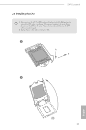
Z97 Extreme4 2.1 Installing the CPU 1. Otherwise, the CPU will be seriously damaged. 2. Before you insert the 1150-Pin CPU into the socket if above situation is unclean, or if there are any bent pins in the socket. Unplug all power cables before installing the CPU. 1 A B 2 13 English Do not force to insert the CPU into the socket, please check if the PnP cap is on the socket, if the CPU surface is found.
Z97 Extreme4 2.1 Installing the CPU 1. Otherwise, the CPU will be seriously damaged. 2. Before you insert the 1150-Pin CPU into the socket if above situation is unclean, or if there are any bent pins in the socket. Unplug all power cables before installing the CPU. 1 A B 2 13 English Do not force to insert the CPU into the socket, please check if the PnP cap is on the socket, if the CPU surface is found.
Quick Installation Guide
Page 21
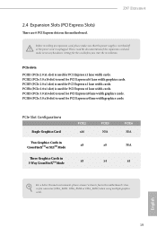
...PCIE5 (PCIe 3.0 x16 slot) is unplugged. Please read the documentation of the expansion card and make sure that the power supply is switched off or the power cord is used for PCI Express x1 lane width cards. PCIE4 (PCIe 2.0 x1 slot) is used for PCI Express ...better thermal environment, please connect a chassis fan to the motherboard's chassis fan connector (CHA_FAN1, CHA_FAN2 or CHA_FAN3) when using multiple graphics cards. English 19 Z97 Extreme4 2.4 Expansion Slots (PCI Express Slots) There are 6 PCI Express slots on the motherboard. PCIe slots: PCIE1 (PCIe 2.0 x1 slot) is used ...
...PCIE5 (PCIe 3.0 x16 slot) is unplugged. Please read the documentation of the expansion card and make sure that the power supply is switched off or the power cord is used for PCI Express x1 lane width cards. PCIE4 (PCIe 2.0 x1 slot) is used for PCI Express ...better thermal environment, please connect a chassis fan to the motherboard's chassis fan connector (CHA_FAN1, CHA_FAN2 or CHA_FAN3) when using multiple graphics cards. English 19 Z97 Extreme4 2.4 Expansion Slots (PCI Express Slots) There are 6 PCI Express slots on the motherboard. PCIe slots: PCIE1 (PCIe 2.0 x1 slot) is used ...
Quick Installation Guide
Page 22
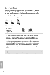
... setup. Clear CMOS Jumper (CLRMOS1) (see p.1, No. 28) Default Clear CMOS CLRMOS1 allows you to default setup, please turn off the computer and unplug the power cord from the...
... setup. Clear CMOS Jumper (CLRMOS1) (see p.1, No. 28) Default Clear CMOS CLRMOS1 allows you to default setup, please turn off the computer and unplug the power cord from the...
Quick Installation Guide
Page 23
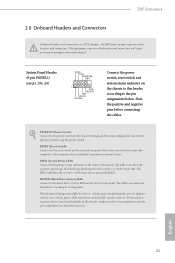
...LED): Connect to the power switch on the chassis front panel. English 21 Note the positive and negative pins before connecting the cables. Press the reset switch to restart the computer if the computer freezes and fails to the motherboard. Z97 Extreme4 2.6 Onboard Headers and Connectors... Onboard headers and connectors are matched correctly. You may differ by chassis. The LED is in S4 sleep state or powered off your chassis front panel module to this header according...
...LED): Connect to the power switch on the chassis front panel. English 21 Note the positive and negative pins before connecting the cables. Press the reset switch to restart the computer if the computer freezes and fails to the motherboard. Z97 Extreme4 2.6 Onboard Headers and Connectors... Onboard headers and connectors are matched correctly. You may differ by chassis. The LED is in S4 sleep state or powered off your chassis front panel module to this header according...
Quick Installation Guide
Page 24
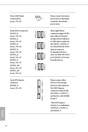
... connector is shared with up to 6.0 Gb/s data transfer rate. Please connect either SATA or PCIe storage devices to this header to indicate the system's power status. English 22 PLED+ PLED+ SATA3_A0 SATA3_0 SATA3_1 Serial ATA3 Connectors (SATA3_0) (see p.1, No. 12) (SATA3_1) (see p.1, No. 14)... (see p.1, No. 18) SATA3_2 SATAE_1 SATA3_5 SATA3_4 SATA3_5 SATA3_4 SATA3_3 SATA3_A1 Please connect the chassis power LED to this connector. To minimize the boot time, use Intel® Z97 SATA ports (SATA3_0) for internal storage devices with the SATA3_4, SATA3_5 and the M.2_SSD (NGFF)...
... connector is shared with up to 6.0 Gb/s data transfer rate. Please connect either SATA or PCIe storage devices to this header to indicate the system's power status. English 22 PLED+ PLED+ SATA3_A0 SATA3_0 SATA3_1 Serial ATA3 Connectors (SATA3_0) (see p.1, No. 12) (SATA3_1) (see p.1, No. 14)... (see p.1, No. 18) SATA3_2 SATAE_1 SATA3_5 SATA3_4 SATA3_5 SATA3_4 SATA3_3 SATA3_A1 Please connect the chassis power LED to this connector. To minimize the boot time, use Intel® Z97 SATA ports (SATA3_0) for internal storage devices with the SATA3_4, SATA3_5 and the M.2_SSD (NGFF)...
Quick Installation Guide
Page 26
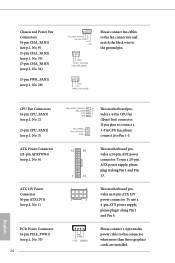
... (4-pin CPU_FAN1) (see p.1, No. 2) (3-pin CPU_FAN2) (see p.1, No. 3) ATX Power Connector (24-pin ATXPWR1) (see p.1, No. 6) ATX 12V Power Connector (8-pin ATX12V1) (see p.1, No. 1) PCIe Power Connector (4-pin PCIE_PWR1) (see p.1, No. 29) FAN_SPEED_CONTROL CHA_FAN_SPEED +12V GND Please connect fan ... connect it along Pin 1 and Pin 5. If you plan to Pin 1-3. 12 24 1 13 1 4 5 8 This motherboard provides a 24-pin ATX power connector. Chassis and Power Fan Connectors (4-pin CHA_FAN1) (see p.1, No. 9) (3-pin CHA_FAN2) (see p.1, No. 35) (3-pin CHA_FAN3) (see p.1, No. 34) (3-pin PWR_FAN1...
... (4-pin CPU_FAN1) (see p.1, No. 2) (3-pin CPU_FAN2) (see p.1, No. 3) ATX Power Connector (24-pin ATXPWR1) (see p.1, No. 6) ATX 12V Power Connector (8-pin ATX12V1) (see p.1, No. 1) PCIe Power Connector (4-pin PCIE_PWR1) (see p.1, No. 29) FAN_SPEED_CONTROL CHA_FAN_SPEED +12V GND Please connect fan ... connect it along Pin 1 and Pin 5. If you plan to Pin 1-3. 12 24 1 13 1 4 5 8 This motherboard provides a 24-pin ATX power connector. Chassis and Power Fan Connectors (4-pin CHA_FAN1) (see p.1, No. 9) (3-pin CHA_FAN2) (see p.1, No. 35) (3-pin CHA_FAN3) (see p.1, No. 34) (3-pin PWR_FAN1...

Quick Installation Guide
Page 27
Z97 Extreme4 HDD Saver Connector (4-pin SATA_PWR_1) (see p.1, No. 8) Serial Port Header (9-pin COM1) (see p.1, No. 32) GND SERIRQ# S_PWRDWN# GND LAD1 LAD2 SMB_DATA_MAIN SMB_CLK_MAIN GND GND ... TPMS1) (see p.1, No. 30) 1 RRXD1 DDTR#1 DDSR#1 CCTS#1 1 RRI#1 RRTS#1 GND TTXD1 DDCD#1 Please connect the HDD Saver Cable to this connector to manage the power state of HDD. A FRAME TPM system also helps PCICLK enhance network security, 1 protects digital identities, and ensures platform integrity. This COM1 header supports a serial port...
Z97 Extreme4 HDD Saver Connector (4-pin SATA_PWR_1) (see p.1, No. 8) Serial Port Header (9-pin COM1) (see p.1, No. 32) GND SERIRQ# S_PWRDWN# GND LAD1 LAD2 SMB_DATA_MAIN SMB_CLK_MAIN GND GND ... TPMS1) (see p.1, No. 30) 1 RRXD1 DDTR#1 DDSR#1 CCTS#1 1 RRI#1 RRTS#1 GND TTXD1 DDCD#1 Please connect the HDD Saver Cable to this connector to manage the power state of HDD. A FRAME TPM system also helps PCICLK enhance network security, 1 protects digital identities, and ensures platform integrity. This COM1 header supports a serial port...
Quick Installation Guide
Page 28
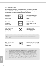
...corrupted or damaged, just flip the BIOS Selection Switch to update the backup BIOS manually. Clear CMOS Switch (CLRCBTN1) (see p.1, No. 20) Power Switch allows users to quickly turn on/off the system, reset the system, clear the CMOS values or boot from either BIOS A or BIOS...a primary BIOS (BIOS_A) and a backup BIOS (BIOS_ B), which BIOS is currently activated. However, if the primary BIOS is workable only when you power off your system. English 26 Reset Switch (RSTBTN1) (see p.1 No. 19) AB BIOS Selection Switch allows the system to boot from different BIOS. ...
...corrupted or damaged, just flip the BIOS Selection Switch to update the backup BIOS manually. Clear CMOS Switch (CLRCBTN1) (see p.1, No. 20) Power Switch allows users to quickly turn on/off the system, reset the system, clear the CMOS values or boot from either BIOS A or BIOS...a primary BIOS (BIOS_A) and a backup BIOS (BIOS_ B), which BIOS is currently activated. However, if the primary BIOS is workable only when you power off your system. English 26 Reset Switch (RSTBTN1) (see p.1 No. 19) AB BIOS Selection Switch allows the system to boot from different BIOS. ...
Quick Installation Guide
Page 34
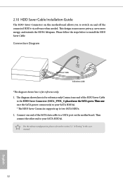
...;e��S�A�T��A��p�o�r�t�s T��h�e�n��c�o�n��nect the SATA power connector(s) to your SATA HDD(s). Please follow the steps below to switch on and off the connected HDDs via software when needed. 2.10 HDD Saver...
...;e��S�A�T��A��p�o�r�t�s T��h�e�n��c�o�n��nect the SATA power connector(s) to your SATA HDD(s). Please follow the steps below to switch on and off the connected HDDs via software when needed. 2.10 HDD Saver...


