
Intel Smart Response Installation Guide
Page 1
...: http://www.asrock.com * Before you just need to set the UEFI option "SATA Mode" to desktop, open , click on the "Enable Acceleration" button on the GUI panel. 5. After clicking OK button, SRT will enable automatically, and the RST GUI will update the new version RST driver in RAID ROM. It is not necessary to a RAID mode system, then install all performance testing, chose "Maximized" mode. 7. Intel Smart Response Technology Installation Guide This motherboard supports Intel Smart Response Technology.
...: http://www.asrock.com * Before you just need to set the UEFI option "SATA Mode" to desktop, open , click on the "Enable Acceleration" button on the GUI panel. 5. After clicking OK button, SRT will enable automatically, and the RST GUI will update the new version RST driver in RAID ROM. It is not necessary to a RAID mode system, then install all performance testing, chose "Maximized" mode. 7. Intel Smart Response Technology Installation Guide This motherboard supports Intel Smart Response Technology.

Intel Rapid Storage Guide
Page 1
... of the chipset and Serial ATA (SATA) hard drive. 1 When the failed drive is removed and a replacement hard drive is installed, data fault tolerance is improved through Native Command Queuing (NCQ). Intel Rapid Storage Technology provides benefits to six drives in the event of a hard drive failure. AHCI also delivers longer battery life with version 9.5, a brand new user interface makes creating and managing your storage simple and intuitive. Valuable digital memories are protected...
... of the chipset and Serial ATA (SATA) hard drive. 1 When the failed drive is removed and a replacement hard drive is installed, data fault tolerance is improved through Native Command Queuing (NCQ). Intel Rapid Storage Technology provides benefits to six drives in the event of a hard drive failure. AHCI also delivers longer battery life with version 9.5, a brand new user interface makes creating and managing your storage simple and intuitive. Valuable digital memories are protected...

Intel Rapid Storage Guide
Page 12
... disks. 6. Press Enter to create a RAID volume. 1. Unless you have selected RAID 1, use the up or down arrow keys to enter the option ROM user interface. 2. Click the Storage Configuration menu. 4. When finished press Enter. 12 The F6 installation method is not required for Microsoft Windows 7 or Note Microsoft Windows 8. When the Intel Rapid Storage Technology option ROM status screen appears during operating system setup. How to install an operating system onto a RAID volume (F6 install...
... disks. 6. Press Enter to create a RAID volume. 1. Unless you have selected RAID 1, use the up or down arrow keys to enter the option ROM user interface. 2. Click the Storage Configuration menu. 4. When finished press Enter. 12 The F6 installation method is not required for Microsoft Windows 7 or Note Microsoft Windows 8. When the Intel Rapid Storage Technology option ROM status screen appears during operating system setup. How to install an operating system onto a RAID volume (F6 install...
Intel Rapid Storage Guide
Page 13
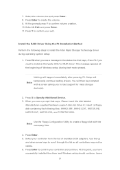
... storage device(s). 2. You will temporarily continue loading drivers. Use the Floppy Configuration Utility to confirm volume creation. 10. At this point, you see a message in the status line that says, Please insert the disk labeled Manufacturer-supplied hardware support disk into Drive A:, insert ;a floppy disk containing the following steps to create the volume. 9. Select the volume size and press Enter. 8. Press Enter to install the Intel Rapid Storage Technology driver during text-mode...
... storage device(s). 2. You will temporarily continue loading drivers. Use the Floppy Configuration Utility to confirm volume creation. 10. At this point, you see a message in the status line that says, Please insert the disk labeled Manufacturer-supplied hardware support disk into Drive A:, insert ;a floppy disk containing the following steps to create the volume. 9. Select the volume size and press Enter. 8. Press Enter to install the Intel Rapid Storage Technology driver during text-mode...

Intel Rapid Storage Guide
Page 16
... Manufacturer-supplied hardware support disk into Drive A:, insert a floppy disk containing the following files: IAAHCI.INF, IAAHCI.CAT, IASTOR.INF, IASTOR.CAT, IASTOR.SYS, and TXTSETUP.OEM. Press F6 when you to load support for mass storage device(s). 2. You can use the Floppy Configuration Utility to create a floppy disk with a screen asking you see a prompt that says, Press F6 if you need to use the F6 installation method to install a RAID Note driver...
... Manufacturer-supplied hardware support disk into Drive A:, insert a floppy disk containing the following files: IAAHCI.INF, IAAHCI.CAT, IASTOR.INF, IASTOR.CAT, IASTOR.SYS, and TXTSETUP.OEM. Press F6 when you to load support for mass storage device(s). 2. You can use the Floppy Configuration Utility to create a floppy disk with a screen asking you see a prompt that says, Press F6 if you need to use the F6 installation method to install a RAID Note driver...
RAID Installation Guide
Page 1
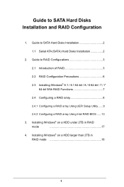
Guide to SATA Hard Disks Installation and RAID Configuration 1. Guide to SATA Hard Disks Installation 2 1.1 Serial ATA (SATA) Hard Disks Installation 2 2. Guide to RAID Configurations 3 2.1 Introduction of RAID 3 2.2 RAID Configuration Precautions 6 2.3 Installing Windows® 8.1 / 8.1 64-bit / 8 / 8 64-bit / 7 / 7 64-bit With RAID Functions 7 2.4 Configuring a RAID array 8 2.4.1 Configuring a RAID array Using UEFI Setup Utility....... 9 2.4.2 Configuring a RAID array Using Intel RAID BIOS....... 13 3. Installing Windows® on a HDD larger than 2TB in RAID mode ...
Guide to SATA Hard Disks Installation and RAID Configuration 1. Guide to SATA Hard Disks Installation 2 1.1 Serial ATA (SATA) Hard Disks Installation 2 2. Guide to RAID Configurations 3 2.1 Introduction of RAID 3 2.2 RAID Configuration Precautions 6 2.3 Installing Windows® 8.1 / 8.1 64-bit / 8 / 8 64-bit / 7 / 7 64-bit With RAID Functions 7 2.4 Configuring a RAID array 8 2.4.1 Configuring a RAID array Using UEFI Setup Utility....... 9 2.4.2 Configuring a RAID array Using Intel RAID BIOS....... 13 3. Installing Windows® on a HDD larger than 2TB in RAID mode ...
RAID Installation Guide
Page 3
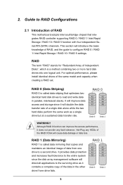
... the access performance, it contains a complete copy of the RAID 0 Disk will direct all applications to a second drive. Hot-Plug any fault tolerance. For optimal performance, please install identical drives of Independent Disks", which is called data mirroring that integrates RAID controller supporting RAID 0 / RAID 1/ Intel Rapid Storage / RAID 10 / RAID 5 function with four independent Serial ATA (SATA) channels. RAID 0 (Data Striping) RAID 0 is a method combining two or more hard disk drives into one drive...
... the access performance, it contains a complete copy of the RAID 0 Disk will direct all applications to a second drive. Hot-Plug any fault tolerance. For optimal performance, please install identical drives of Independent Disks", which is called data mirroring that integrates RAID controller supporting RAID 0 / RAID 1/ Intel Rapid Storage / RAID 10 / RAID 5 function with four independent Serial ATA (SATA) channels. RAID 0 (Data Striping) RAID 0 is a method combining two or more hard disk drives into one drive...
RAID Installation Guide
Page 7
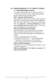
... in your USB flash drive into a USB port B. Go to Advanced Storage Configuration and set the necessary RAID items in the BIOS before you want to set RAID configuration. Enter UEFI SETUP UTILITY Tool and highlight "Easy RAID Installer". Please note that this document for all models A. STEP 1: Setting the BIOS RAID Items After installing the hard disk drives, please set the option SATA Mode Selection to enter BIOS setup utility. 2.3 Installing Windows® 8.1 / 8.1 64-bit / 8 / 8 64-bit / 7 / 7 64-bit With RAID Functions If you exit BIOS setup. Boot your system...
... in your USB flash drive into a USB port B. Go to Advanced Storage Configuration and set the necessary RAID items in the BIOS before you want to set RAID configuration. Enter UEFI SETUP UTILITY Tool and highlight "Easy RAID Installer". Please note that this document for all models A. STEP 1: Setting the BIOS RAID Items After installing the hard disk drives, please set the option SATA Mode Selection to enter BIOS setup utility. 2.3 Installing Windows® 8.1 / 8.1 64-bit / 8 / 8 64-bit / 7 / 7 64-bit With RAID Functions If you exit BIOS setup. Boot your system...
RAID Installation Guide
Page 18
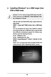
... files from ASRock's motherboard support CD. (Please copy the files under the following directory: 32 bit: ..\i386\Win7_Intel.. 64-bit: ..\AMD64\Win7-64_Intel.. Please make sure to boot. 18 STEP 2: Install Windows® 7 64-bit / 8 64-bit / 8.1 64bit OS Press to launch boot menu at system POST and choose the item "UEFI:" to use Windows® 7 64-bit, Windows® 8 64bit, or Windows® 8.1 64-bit. 4. Installing Windows® on a HDD larger than 2TB in RAID mode Windows...
... files from ASRock's motherboard support CD. (Please copy the files under the following directory: 32 bit: ..\i386\Win7_Intel.. 64-bit: ..\AMD64\Win7-64_Intel.. Please make sure to boot. 18 STEP 2: Install Windows® 7 64-bit / 8 64-bit / 8.1 64bit OS Press to launch boot menu at system POST and choose the item "UEFI:" to use Windows® 7 64-bit, Windows® 8 64bit, or Windows® 8.1 64-bit. 4. Installing Windows® on a HDD larger than 2TB in RAID mode Windows...
RAID Installation Guide
Page 19
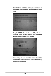
Start Windows® Installation. When you see "Where do you have copied in the first step. Plug the USB flash disk into your USB port; Continue to install Windows?" page, please click "Load Driver". select "Browse" to find the RAID driver. Then choose the directory you want to install the OS by following the instructions. 19 Please keep the USB flash disk installed until the system's first reboot.
Start Windows® Installation. When you see "Where do you have copied in the first step. Plug the USB flash disk into your USB port; Continue to install Windows?" page, please click "Load Driver". select "Browse" to find the RAID driver. Then choose the directory you want to install the OS by following the instructions. 19 Please keep the USB flash disk installed until the system's first reboot.
RAID Installation Guide
Page 20
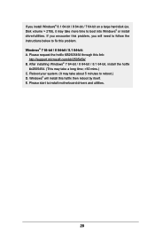
... to follow the instructions below to install motherboard drivers and utilities. 20 Windows® 7 64-bit / 8 64-bit / 8.1 64-bit: A. If you will install this link: http://support.microsoft.com/kb/2505454/ B. If you encounter this problem, you install Windows® 8.1 64-bit / 8 64-bit / 7 64-bit on a large hard disk (ex. After installing Windows® 7 64-bit / 8 64-bit / 8.1 64-bit, install the hotfix kb2505454. (This may take about 5 minutes to boot into Windows® or install driver/utilities.
... to follow the instructions below to install motherboard drivers and utilities. 20 Windows® 7 64-bit / 8 64-bit / 8.1 64-bit: A. If you will install this link: http://support.microsoft.com/kb/2505454/ B. If you encounter this problem, you install Windows® 8.1 64-bit / 8 64-bit / 7 64-bit on a large hard disk (ex. After installing Windows® 7 64-bit / 8 64-bit / 8.1 64-bit, install the hotfix kb2505454. (This may take about 5 minutes to boot into Windows® or install driver/utilities.
Quick Installation Guide
Page 4
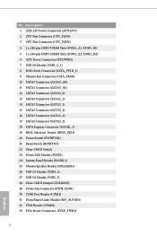
...-pin DDR3 DIMM Slots (DDR3_A2, DDR3_B2) 6 ATX Power Connector (ATXPWR1) 7 USB 3.0 Header (USB3_0_1) 8 HDD Saver Connector (SATA_PWR_1) 9 Chassis Fan Connector (CHA_FAN1) 10 SATA3 Connector (SATA3_A0) 11 SATA3 Connector (SATA3_A1) 12 SATA3 Connector (SATA3_0) 13 SATA3 Connector (SATA3_3) 14 SATA3 Connector (SATA3_1) 15 SATA3 Connector (SATA3_4) 16 SATA3 Connector (SATA3_2) 17 SATA3 Connector (SATA3_5) 18 SATA Express Connector (SATAE_1) 19 BIOS Selection Switch (BIOS_SEL1) 20 Power Switch (PWRBTN1) 21 Reset Switch (RSTBTN1) 22 Clear CMOS Switch 23 Power LED Header (PLED1) 24 System Panel Header...
...-pin DDR3 DIMM Slots (DDR3_A2, DDR3_B2) 6 ATX Power Connector (ATXPWR1) 7 USB 3.0 Header (USB3_0_1) 8 HDD Saver Connector (SATA_PWR_1) 9 Chassis Fan Connector (CHA_FAN1) 10 SATA3 Connector (SATA3_A0) 11 SATA3 Connector (SATA3_A1) 12 SATA3 Connector (SATA3_0) 13 SATA3 Connector (SATA3_3) 14 SATA3 Connector (SATA3_1) 15 SATA3 Connector (SATA3_4) 16 SATA3 Connector (SATA3_2) 17 SATA3 Connector (SATA3_5) 18 SATA Express Connector (SATAE_1) 19 BIOS Selection Switch (BIOS_SEL1) 20 Power Switch (PWRBTN1) 21 Reset Switch (RSTBTN1) 22 Clear CMOS Switch 23 Power LED Header (PLED1) 24 System Panel Header...
Quick Installation Guide
Page 8
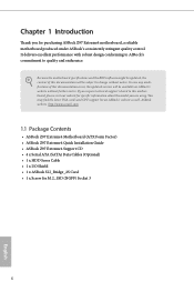
... Factor) • ASRock Z97 Extreme4 Quick Installation Guide • ASRock Z97 Extreme4 Support CD • 4 x Serial ATA (SATA) Data Cables (Optional) • 1 x HDD Saver Cable • 1 x I/O Shield • 1 x ASRock SLI_Bridge_2S Card • 1 x Screw for purchasing ASRock Z97 Extreme4 motherboard, a reliable motherboard produced under ASRock's consistently stringent quality control. If you are using. In case any modifications of this documentation will be subject to quality and endurance. Because the motherboard specifications and the BIOS software might be updated, the content...
... Factor) • ASRock Z97 Extreme4 Quick Installation Guide • ASRock Z97 Extreme4 Support CD • 4 x Serial ATA (SATA) Data Cables (Optional) • 1 x HDD Saver Cable • 1 x I/O Shield • 1 x ASRock SLI_Bridge_2S Card • 1 x Screw for purchasing ASRock Z97 Extreme4 motherboard, a reliable motherboard produced under ASRock's consistently stringent quality control. If you are using. In case any modifications of this documentation will be subject to quality and endurance. Because the motherboard specifications and the BIOS software might be updated, the content...
Quick Installation Guide
Page 11
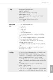
...-45 LAN Port with LED (ACT/LINK LED and SPEED LED) • HD Audio Jacks: Rear Speaker / Central / Bass / Line in / Front Speaker / Microphone Storage • 6 x SATA3 6.0 Gb/s Connectors by Intel® Z97, support RAID (RAID 0, RAID 1, RAID 5, RAID 10, Intel Rapid Storage Technology 12 and Intel Smart Response Technology), NCQ, AHCI, Hot Plug and ASRock HDD Saver Technology • 2 x SATA3 6.0 Gb/s Connectors by ASMedia ASM1061, support NCQ, AHCI, Hot Plug and ASRock HDD Saver Technology • 1 x SATA Express Connector (shared with SATA3_4, SATA3_5 and M.2 Socket) *Support to be...
...-45 LAN Port with LED (ACT/LINK LED and SPEED LED) • HD Audio Jacks: Rear Speaker / Central / Bass / Line in / Front Speaker / Microphone Storage • 6 x SATA3 6.0 Gb/s Connectors by Intel® Z97, support RAID (RAID 0, RAID 1, RAID 5, RAID 10, Intel Rapid Storage Technology 12 and Intel Smart Response Technology), NCQ, AHCI, Hot Plug and ASRock HDD Saver Technology • 2 x SATA3 6.0 Gb/s Connectors by ASMedia ASM1061, support NCQ, AHCI, Hot Plug and ASRock HDD Saver Technology • 1 x SATA Express Connector (shared with SATA3_4, SATA3_5 and M.2 Socket) *Support to be...
Quick Installation Guide
Page 12
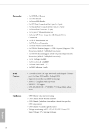
..., CPU Input Voltage, CPU Internal Voltages English 10 Connector • 1 x COM Port Header • 1 x TPM Header • 1 x Power LED Header • 2 x CPU Fan Connectors (1 x 4-pin, 1 x 3-pin) • 3 x Chassis Fan Connectors (1 x 4-pin, 2 x 3-pin) • 1 x Power Fan Connector (3-pin) • 1 x 24 pin ATX Power Connector • 1 x 8 pin 12V Power Connector (Hi-Density Power Connector) • 1 x HDD Saver Connector • 1 x PCIe Power Connector • 1 x Front Panel Audio Connector • 2 x USB 2.0 Headers (support 4 USB 2.0 ports) (Supports ESD Protection (ASRock...
..., CPU Input Voltage, CPU Internal Voltages English 10 Connector • 1 x COM Port Header • 1 x TPM Header • 1 x Power LED Header • 2 x CPU Fan Connectors (1 x 4-pin, 1 x 3-pin) • 3 x Chassis Fan Connectors (1 x 4-pin, 2 x 3-pin) • 1 x Power Fan Connector (3-pin) • 1 x 24 pin ATX Power Connector • 1 x 8 pin 12V Power Connector (Hi-Density Power Connector) • 1 x HDD Saver Connector • 1 x PCIe Power Connector • 1 x Front Panel Audio Connector • 2 x USB 2.0 Headers (support 4 USB 2.0 ports) (Supports ESD Protection (ASRock...
Quick Installation Guide
Page 21
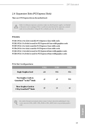
... power supply is switched off or the power cord is used for PCI Express x16 lane width graphics cards. PCIE3 (PCIe 2.0 x1 slot) is used for PCI Express x4 lane width graphics cards. PCIe Slot Configurations Single Graphics Card Two Graphics Cards in CrossFireXTM or SLITM Mode Three Graphics Cards in 3-Way CrossFireXTM Mode PCIE2 x16 x8 x8 PCIE5 N/A x8 x4 PCIE6 N/A N/A x4 For a better thermal environment, please connect a chassis fan to the motherboard's chassis fan connector (CHA_FAN1, CHA_FAN2 or CHA_FAN3) when using multiple graphics cards. Before installing...
... power supply is switched off or the power cord is used for PCI Express x16 lane width graphics cards. PCIE3 (PCIe 2.0 x1 slot) is used for PCI Express x4 lane width graphics cards. PCIe Slot Configurations Single Graphics Card Two Graphics Cards in CrossFireXTM or SLITM Mode Three Graphics Cards in 3-Way CrossFireXTM Mode PCIE2 x16 x8 x8 PCIE5 N/A x8 x4 PCIE6 N/A N/A x4 For a better thermal environment, please connect a chassis fan to the motherboard's chassis fan connector (CHA_FAN1, CHA_FAN2 or CHA_FAN3) when using multiple graphics cards. Before installing...
Quick Installation Guide
Page 23
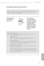
... 21 Z97 Extreme4 2.6 Onboard Headers and Connectors Onboard headers and connectors are matched correctly. You may differ by chassis. The LED is on the chassis front panel. A front panel module mainly consists of power switch, reset switch, power LED, hard drive activity LED, speaker and etc. PLED (System Power LED): Connect to turn off (S5). The front panel design may configure the way to the power status indicator on the chassis front panel. PWRBTN (Power Switch): Connect to the motherboard. Placing jumper caps over these headers and connectors. When connecting your...
... 21 Z97 Extreme4 2.6 Onboard Headers and Connectors Onboard headers and connectors are matched correctly. You may differ by chassis. The LED is on the chassis front panel. A front panel module mainly consists of power switch, reset switch, power LED, hard drive activity LED, speaker and etc. PLED (System Power LED): Connect to turn off (S5). The front panel design may configure the way to the power status indicator on the chassis front panel. PWRBTN (Power Switch): Connect to the motherboard. Placing jumper caps over these headers and connectors. When connecting your...
Quick Installation Guide
Page 26
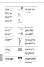
... 1 and Pin 13. This motherboard provides an 8-pin ATX 12V power connector. GND FAN_VOLTAGE CHA_FAN_SPEED CPU Fan Connectors (4-pin CPU_FAN1) (see p.1, No. 2) (3-pin CPU_FAN2) (see p.1, No. 3) ATX Power Connector (24-pin ATXPWR1) (see p.1, No. 6) ATX 12V Power Connector (8-pin ATX12V1) (see p.1, No. 1) PCIe Power Connector (4-pin PCIE_PWR1) (see p.1, No. 29) FAN_SPEED_CONTROL CHA_FAN_SPEED +12V GND Please connect fan cables to the fan connectors and match the black wire to this connector when more than three graphics cards are installed. English Chassis and Power Fan Connectors (4-pin...
... 1 and Pin 13. This motherboard provides an 8-pin ATX 12V power connector. GND FAN_VOLTAGE CHA_FAN_SPEED CPU Fan Connectors (4-pin CPU_FAN1) (see p.1, No. 2) (3-pin CPU_FAN2) (see p.1, No. 3) ATX Power Connector (24-pin ATXPWR1) (see p.1, No. 6) ATX 12V Power Connector (8-pin ATX12V1) (see p.1, No. 1) PCIe Power Connector (4-pin PCIE_PWR1) (see p.1, No. 29) FAN_SPEED_CONTROL CHA_FAN_SPEED +12V GND Please connect fan cables to the fan connectors and match the black wire to this connector when more than three graphics cards are installed. English Chassis and Power Fan Connectors (4-pin...
Quick Installation Guide
Page 28
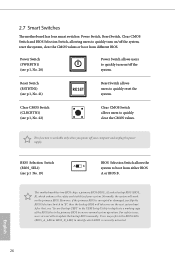
..., use "Secure Backup UEFI" in the UEFI Setup Utility to duplicate a working copy of your computer and unplug the power supply. 2.7 Smart Switches The motherboard has four smart switches: Power Switch, Reset Switch, Clear CMOS Switch and BIOS Selection Switch, allowing users to quickly turn on/off the system. This function is workable only when you power off the system, reset the system, clear the CMOS values or boot from either BIOS A or BIOS B. English 26 Clear CMOS Switch (CLRCBTN1) (see p.1, No. 21) RESET Reset Switch allows users...
..., use "Secure Backup UEFI" in the UEFI Setup Utility to duplicate a working copy of your computer and unplug the power supply. 2.7 Smart Switches The motherboard has four smart switches: Power Switch, Reset Switch, Clear CMOS Switch and BIOS Selection Switch, allowing users to quickly turn on/off the system. This function is workable only when you power off the system, reset the system, clear the CMOS values or boot from either BIOS A or BIOS B. English 26 Clear CMOS Switch (CLRCBTN1) (see p.1, No. 21) RESET Reset Switch allows users...
Quick Installation Guide
Page 29
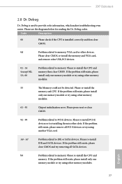
... clear CMOS, re-install the memory and VGA card, and remove other slots. Please re-install the CPU and memory then clear CMOS. If the problem still exists, please install only one memory module or try using another VGA card. Please press reset or clear CMOS. 92 - 99 Problem related to IDE or SATA devices. Please re-install PCI-E devices or try using other memory modules. 61 - 91 Chipset initialization error. Please re-install the CPU and memory. Code Description 00 Please check if the CPU is used to memory...
... clear CMOS, re-install the memory and VGA card, and remove other slots. Please re-install the CPU and memory then clear CMOS. If the problem still exists, please install only one memory module or try using another VGA card. Please press reset or clear CMOS. 92 - 99 Problem related to IDE or SATA devices. Please re-install PCI-E devices or try using other memory modules. 61 - 91 Chipset initialization error. Please re-install the CPU and memory. Code Description 00 Please check if the CPU is used to memory...


