Intel Rapid Storage Guide
Page 13
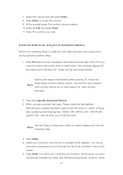
....SYS, and TXTSETUP.OEM. Press S to confirm volume creation. 10. Use the Floppy Configuration Utility to load support for mass storage device(s). 2. Press Enter. 5. At this point, you to create a floppy disk with a screen asking you have successfully installed the driver and Windows setup should continue. Nothing will temporarily continue loading drivers. 7. Press Enter to install a third party SCSI or RAID driver. When you see a prompt that says, Press F6 if you...
....SYS, and TXTSETUP.OEM. Press S to confirm volume creation. 10. Use the Floppy Configuration Utility to load support for mass storage device(s). 2. Press Enter. 5. At this point, you to create a floppy disk with a screen asking you have successfully installed the driver and Windows setup should continue. Nothing will temporarily continue loading drivers. 7. Press Enter to install a third party SCSI or RAID driver. When you see a prompt that says, Press F6 if you...

Intel Smart Response Installation Guide
Page 1
... panel. 5. When pop-up menu appears, chose which SSD you wish to use as the Cache device, which HDD you wish to Accelerate, if you want to use the full SSD as Cache device or only 20GB, and if you just need to set the UEFI option "SATA Mode" to show the newly accelerated system configuration. * Intel® will update the new version RST driver in RAID ROM...
... panel. 5. When pop-up menu appears, chose which SSD you wish to use as the Cache device, which HDD you wish to Accelerate, if you want to use the full SSD as Cache device or only 20GB, and if you just need to set the UEFI option "SATA Mode" to show the newly accelerated system configuration. * Intel® will update the new version RST driver in RAID ROM...
User Manual
Page 8
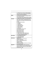
...with LED - 64Mb AMI BIOS - OEM and Trial; Front panel audio connector - 4 x USB 2.0 headers (support 8 USB 2.0 ports) - 1 x USB 3.0 header (supports 2 USB 3.0 ports) - 1 x Dr. Debug (7-Segment Debug LED) - 1 x Clear CMOS Switch with LED - 1 x Power Switch with LED - 1 x Reset Switch with GUI support - ACPI 1.1 Compliance Wake Up Events - SMBIOS 2.3.1 Support - OEM) 8 CPU Core, IGPU, DRAM, PCH, CPU PLL, VTT, VCCSA Voltage Multi-adjustment - USB3.0 Connector Smart Switch BIOS Feature Support CD - 4 x SATA3 6.0 Gb/s connectors by ASMedia ASM1061, support NCQ, AHCI and "Hot Plug...
...with LED - 64Mb AMI BIOS - OEM and Trial; Front panel audio connector - 4 x USB 2.0 headers (support 8 USB 2.0 ports) - 1 x USB 3.0 header (supports 2 USB 3.0 ports) - 1 x Dr. Debug (7-Segment Debug LED) - 1 x Clear CMOS Switch with LED - 1 x Power Switch with LED - 1 x Reset Switch with GUI support - ACPI 1.1 Compliance Wake Up Events - SMBIOS 2.3.1 Support - OEM) 8 CPU Core, IGPU, DRAM, PCH, CPU PLL, VTT, VCCSA Voltage Multi-adjustment - USB3.0 Connector Smart Switch BIOS Feature Support CD - 4 x SATA3 6.0 Gb/s connectors by ASMedia ASM1061, support NCQ, AHCI and "Hot Plug...
User Manual
Page 10
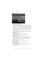
..., PCIE4 and PCIE6 slots will be enabled at PCI Express Gen 2 speed. In Hardware Monitor, it on page 14 for the operation procedures of "Hyper Threading Technology", please check page 72. 2. DDR3 frequency options may be disabled. For audio output, this motherboard supports 2-channel, 4-channel, 6-channel, and 8-channel modes. Please check the table on PCIE2 slot; This motherboard supports Dual Channel Memory Technology. Only K-Series CPU can support DDR3 overclock to read the installation guide of memory modules on the processor. To run...
..., PCIE4 and PCIE6 slots will be enabled at PCI Express Gen 2 speed. In Hardware Monitor, it on page 14 for the operation procedures of "Hyper Threading Technology", please check page 72. 2. DDR3 frequency options may be disabled. For audio output, this motherboard supports 2-channel, 4-channel, 6-channel, and 8-channel modes. Please check the table on PCIE2 slot; This motherboard supports Dual Channel Memory Technology. Only K-Series CPU can support DDR3 overclock to read the installation guide of memory modules on the processor. To run...
User Manual
Page 11
...-go. Just launch this utility, you can press key during the POST or press key to BIOS setup menu to 40% faster than ever. ASRock motherboards are assured to your USB flash drive, floppy disk or hard drive, then you can update your browser version is a BIOS flash utility embedded in a few clicks without entering operating systems first like MS-DOS or Windows®. If you...
...-go. Just launch this utility, you can press key during the POST or press key to BIOS setup menu to 40% faster than ever. ASRock motherboards are assured to your USB flash drive, floppy disk or hard drive, then you can update your browser version is a BIOS flash utility embedded in a few clicks without entering operating systems first like MS-DOS or Windows®. If you...
User Manual
Page 34
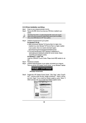
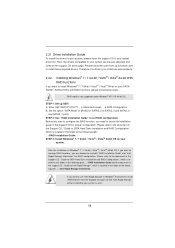
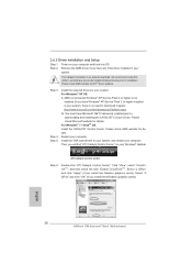
... item "Enable CrossFireXTM". 2.8.2 Driver Installation and Setup Step 1. You must have any previously installed Catalyst drivers prior to downloading and installing the CATALYST Control Center. AMD recommends Windows® XP Service Pack 2 or higher to be installed (If you have Microsoft .NET Framework installed prior to installation. Restart your system. We recommend using this utility to uninstall any VGA driver installed in your system, there is an optional download. ATI Catalyst Control Center...
... item "Enable CrossFireXTM". 2.8.2 Driver Installation and Setup Step 1. You must have any previously installed Catalyst drivers prior to downloading and installing the CATALYST Control Center. AMD recommends Windows® XP Service Pack 2 or higher to be installed (If you have Microsoft .NET Framework installed prior to installation. Restart your system. We recommend using this utility to uninstall any VGA driver installed in your system, there is an optional download. ATI Catalyst Control Center...
User Manual
Page 36
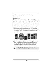
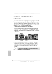
... I/O panel, connect D-Sub monitor cable to D-Sub port on the I/O panel, connect HDMI monitor cable to HDMI port on the I/O panel, or connect DisplayPort monitor cable to support dual VGA output so that DVI-D, D-sub, HDMI and DisplayPort can freely enjoy the benefits of dual monitor function after your computer. This motherboard also provides independent display controllers for DVI-D, D-Sub, HDMI and DisplayPort to DisplayPort on VGA card to your system and restart your system boots. To enable dual monitor...
... I/O panel, connect D-Sub monitor cable to D-Sub port on the I/O panel, connect HDMI monitor cable to HDMI port on the I/O panel, or connect DisplayPort monitor cable to support dual VGA output so that DVI-D, D-sub, HDMI and DisplayPort can freely enjoy the benefits of dual monitor function after your computer. This motherboard also provides independent display controllers for DVI-D, D-Sub, HDMI and DisplayPort to DisplayPort on VGA card to your system and restart your system boots. To enable dual monitor...
User Manual
Page 58
.... Set the option "SATA Mode" to [RAID] for proper configuration. STEP 2: Use "RAID Installation Guide" to SATA2_5 and SATA3_0 and SATA3_1 ports. STEP 1: Set up to bottom side to install Windows® 7 / 7 64-bit / VistaTM / VistaTM 64-bit on your SATA / SATAII / SATA3 HDDs with RAID functions, please follow the order from the Support CD again so that "Intel Rapid Storage" will be auto-detected and listed on your optical drive...
.... Set the option "SATA Mode" to [RAID] for proper configuration. STEP 2: Use "RAID Installation Guide" to SATA2_5 and SATA3_0 and SATA3_1 ports. STEP 1: Set up to bottom side to install Windows® 7 / 7 64-bit / VistaTM / VistaTM 64-bit on your SATA / SATAII / SATA3 HDDs with RAID functions, please follow the order from the Support CD again so that "Intel Rapid Storage" will be auto-detected and listed on your optical drive...
User Manual
Page 72
... the installed CPU does not support Hyper-Threading technology. The default value is [All]. Configuration options: [All], [1] and [2]. In the C1 power state, the processor maintains the context of cores to [Enabled] if using Microsoft® Windows® XP, VistaTM, 7, or Linux kernel version 2.4.18 or higher. This option will program into C State package limit register. The default value is [Auto]. 72 CPU C6 State Support Use...
... the installed CPU does not support Hyper-Threading technology. The default value is [All]. Configuration options: [All], [1] and [2]. In the C1 power state, the processor maintains the context of cores to [Enabled] if using Microsoft® Windows® XP, VistaTM, 7, or Linux kernel version 2.4.18 or higher. This option will program into C State package limit register. The default value is [Auto]. 72 CPU C6 State Support Use...

User Manual
Page 82
...option to enable or disable legacy support for USB devices. Enables support for the details of USB 2.0 controller. There are connected. [Disabled] - Legacy USB 3.0 Support Use this option to use under UEFI setup and Windows / Linux OS. Enables legacy support if USB devices are four configuration options: [Enabled], [Auto], [Disabled] and [UEFI Setup Only]. USB devices are not allowed to select legacy support for USB 3.0 devices. The default value is recommended to select [Disabled] to below descriptions for legacy USB. [Auto] - Please refer to enter OS. [UEFI Setup...
...option to enable or disable legacy support for USB devices. Enables support for the details of USB 2.0 controller. There are connected. [Disabled] - Legacy USB 3.0 Support Use this option to use under UEFI setup and Windows / Linux OS. Enables legacy support if USB devices are four configuration options: [Enabled], [Auto], [Disabled] and [UEFI Setup Only]. USB devices are not allowed to select legacy support for USB 3.0 devices. The default value is recommended to select [Disabled] to below descriptions for legacy USB. [Auto] - Please refer to enter OS. [UEFI Setup...
User Manual
Page 87
... more about ASRock, welcome to display the menus. 4.2.2 Drivers Menu The Drivers Menu shows the available devices drivers if the system detects installed devices. or you need to contact ASRock or want to know more information. 4.2 Support CD Information The Support CD that came with the motherboard contains necessary drivers and useful utilities that the motherboard supports. Please install the necessary drivers to your computer. Because motherboard settings and hardware options vary, use the setup procedures...
... more about ASRock, welcome to display the menus. 4.2.2 Drivers Menu The Drivers Menu shows the available devices drivers if the system detects installed devices. or you need to contact ASRock or want to know more information. 4.2 Support CD Information The Support CD that came with the motherboard contains necessary drivers and useful utilities that the motherboard supports. Please install the necessary drivers to your computer. Because motherboard settings and hardware options vary, use the setup procedures...
Quick Installation Guide
Page 2
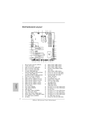
...) 17 Power Switch (PWRBTN) 39 PCI Express 2.0 x16 Slot (PCIE5, Black) 18 64Mb SPI Flash 40 PCI Slot (PCI1) 19 Clear CMOS Jumper (CLRCMOS1) 41 PCI Express 2.0 x16 Slot (PCIE4, Black) 20 Power LED Header (PLED1) 42 PCI Express 2.0 x1 Slot (PCIE3, Black) 21 System Panel Header (PANEL1, Black) 43 PCI Express 3.0 x16 Slot (PCIE2, Black) 22 Chassis Speaker Header (SPEAKER 1, Black) 44 PCI Express 2.0 x16 Slot (PCIE1, Black) 23 Clear CMOS Switch (CLRCBTN) 45 SLI / XFIRE Power Connector 24 Dr. Debug 46 Chassis Fan Connector (CHA_FAN3) 2 ASRock Z68 Extreme7 Gen3 Motherboard English
...) 17 Power Switch (PWRBTN) 39 PCI Express 2.0 x16 Slot (PCIE5, Black) 18 64Mb SPI Flash 40 PCI Slot (PCI1) 19 Clear CMOS Jumper (CLRCMOS1) 41 PCI Express 2.0 x16 Slot (PCIE4, Black) 20 Power LED Header (PLED1) 42 PCI Express 2.0 x1 Slot (PCIE3, Black) 21 System Panel Header (PANEL1, Black) 43 PCI Express 3.0 x16 Slot (PCIE2, Black) 22 Chassis Speaker Header (SPEAKER 1, Black) 44 PCI Express 2.0 x16 Slot (PCIE1, Black) 23 Clear CMOS Switch (CLRCBTN) 45 SLI / XFIRE Power Connector 24 Dr. Debug 46 Chassis Fan Connector (CHA_FAN3) 2 ASRock Z68 Extreme7 Gen3 Motherboard English
Quick Installation Guide
Page 3
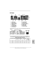
... (Pink) USB 3.0 Ports (USB34) IEEE 1394 Port (IEEE 1394) eSATA3 Connector HDMI Port (HDMI1) DVI-D Port (DVI1) USB 3.0 Ports (USB12) * There are two LED next to the table below for Audio Output Connection Audio Output Channels Front Speaker Rear Speaker Central / Bass Line In or (No. 10) (No. 7) (No. 6) Side Speaker (No. 9) 2 V -- -- -- 4 V V -- -- 6 V V V -- 8 V V V V English 3 ASRock Z68 Extreme7 Gen3 Motherboard TABLE for connection details in accordance with the type of speaker you use . Please refer to the LAN port. See...
... (Pink) USB 3.0 Ports (USB34) IEEE 1394 Port (IEEE 1394) eSATA3 Connector HDMI Port (HDMI1) DVI-D Port (DVI1) USB 3.0 Ports (USB12) * There are two LED next to the table below for Audio Output Connection Audio Output Channels Front Speaker Rear Speaker Central / Bass Line In or (No. 10) (No. 7) (No. 6) Side Speaker (No. 9) 2 V -- -- -- 4 V V -- -- 6 V V V -- 8 V V V V English 3 ASRock Z68 Extreme7 Gen3 Motherboard TABLE for connection details in accordance with the type of speaker you use . Please refer to the LAN port. See...
Quick Installation Guide
Page 5
...found in the user manual presented in , 30.5 cm x 24.4 cm) ASRock Z68 Extreme7 Gen3 Quick Installation Guide ASRock Z68 Extreme7 Gen3 Support CD 6 x Serial ATA (SATA) Data Cables (Optional) 2 x Serial ATA (SATA) HDD Power Cables (Optional) 1 x 3.5mm Audio Cable (Optional) 1 x I/O Panel Shield 1 x Front USB 3.0 Panel 4 x HDD Screws 6 x Chassis Screws 1 x Rear USB 3.0 Bracket 1 x ASRock SLI_Bridge_2S Card 1 x ASRock 3-Way SLI-2S2S Bridge Card 1 x PS/2 Mouse/Keyboard + USB 2.0 Bracket ASRock Reminds You... In case any modifications of the motherboard can be available on ASRock website as...
...found in the user manual presented in , 30.5 cm x 24.4 cm) ASRock Z68 Extreme7 Gen3 Quick Installation Guide ASRock Z68 Extreme7 Gen3 Support CD 6 x Serial ATA (SATA) Data Cables (Optional) 2 x Serial ATA (SATA) HDD Power Cables (Optional) 1 x 3.5mm Audio Cable (Optional) 1 x I/O Panel Shield 1 x Front USB 3.0 Panel 4 x HDD Screws 6 x Chassis Screws 1 x Rear USB 3.0 Bracket 1 x ASRock SLI_Bridge_2S Card 1 x ASRock 3-Way SLI-2S2S Bridge Card 1 x PS/2 Mouse/Keyboard + USB 2.0 Bracket ASRock Reminds You... In case any modifications of the motherboard can be available on ASRock website as...
Quick Installation Guide
Page 8
... DVD Suite - Supports "Plug and Play" - CPU/Chassis/Power FAN connector - 24 pin ATX power connector - 8 pin 12V power connector - OEM) ASRock Z68 Extreme7 Gen3 Motherboard English USB3.0 Connector Smart Switch BIOS Feature Support CD 8 - 4 x SATA3 6.0 Gb/s connectors by ASMedia ASM1042, supports USB 1.0/2.0/3.0 up to 5Gb/s - 4 x SATA2 3.0 Gb/s connectors, support RAID (RAID 0, RAID 1, RAID 10, RAID 5, Intel Rapid Storage and Intel Smart Response Technology), NCQ, AHCI and Hot Plug functions - 6 x SATA3 6.0Gb/s connectors - 1 x IR header - 1 x CIR header - 1 x COM port header...
... DVD Suite - Supports "Plug and Play" - CPU/Chassis/Power FAN connector - 24 pin ATX power connector - 8 pin 12V power connector - OEM) ASRock Z68 Extreme7 Gen3 Motherboard English USB3.0 Connector Smart Switch BIOS Feature Support CD 8 - 4 x SATA3 6.0 Gb/s connectors by ASMedia ASM1042, supports USB 1.0/2.0/3.0 up to 5Gb/s - 4 x SATA2 3.0 Gb/s connectors, support RAID (RAID 0, RAID 1, RAID 10, RAID 5, Intel Rapid Storage and Intel Smart Response Technology), NCQ, AHCI and Hot Plug functions - 6 x SATA3 6.0Gb/s connectors - 1 x IR header - 1 x CIR header - 1 x COM port header...
Quick Installation Guide
Page 10
... motherboard supports Dual Channel Memory Technology. Please refer to 2133 and 1866. 4. In Fan Control, it shows the major readings of "User Manual" in a user-friendly interface, which is no such limitation. 5. Only K-Series CPU can load the OC profile to their own system to use two of ASRock Extreme Tuning Utility (AXTU). Please check Intel® website for proper installation. 6. Please check the table on the processor...
... motherboard supports Dual Channel Memory Technology. Please refer to 2133 and 1866. 4. In Fan Control, it shows the major readings of "User Manual" in a user-friendly interface, which is no such limitation. 5. Only K-Series CPU can load the OC profile to their own system to use two of ASRock Extreme Tuning Utility (AXTU). Please check Intel® website for proper installation. 6. Please check the table on the processor...
Quick Installation Guide
Page 11
... Apple devices simultaneously and even supports continuous charging when your PC enters into an enhanced view for IE that the USB flash drive or hard drive must use SmartView feature, please make sure your OS version is Windows® 7 / 7 64 bit / VistaTM / VistaTM 64 bit, and your browser version is the best and fastest technology to RAM (S3), hibernation mode (S4) or power off (S5). ASRock XFast...
... Apple devices simultaneously and even supports continuous charging when your PC enters into an enhanced view for IE that the USB flash drive or hard drive must use SmartView feature, please make sure your OS version is Windows® 7 / 7 64 bit / VistaTM / VistaTM 64 bit, and your browser version is the best and fastest technology to RAM (S3), hibernation mode (S4) or power off (S5). ASRock XFast...
Quick Installation Guide
Page 30
... Service Pack 2 or higher to download it again): http://www.microsoft.com/windowsxp/sp2/default.mspx B. Double-click "ATI Catalyst Control Center". English 30 ASRock Z68 Extreme7 Gen3 Motherboard Install the required drivers to your system, and restart your computer. Then you install two Radeon graphics cards). Select "2 GPUs" and click "Apply" (if you will find "ATI Catalyst Control Center" on your computer. Remove the AMD driver...
... Service Pack 2 or higher to download it again): http://www.microsoft.com/windowsxp/sp2/default.mspx B. Double-click "ATI Catalyst Control Center". English 30 ASRock Z68 Extreme7 Gen3 Motherboard Install the required drivers to your system, and restart your computer. Then you install two Radeon graphics cards). Select "2 GPUs" and click "Apply" (if you will find "ATI Catalyst Control Center" on your computer. Remove the AMD driver...
Quick Installation Guide
Page 32
... display contents. D-Sub, DVI-D, HDMI and DisplayPort monitors cannot be enabled at the same time. To enable dual monitor feature, please follow the below steps: 1. English 32 ASRock Z68 Extreme7 Gen3 Motherboard With the internal VGA output support (DVI-D, D-Sub, HDMI and DisplayPort), you can easily enjoy the benefits of dual monitor feature without installing any add-on the I/O panel. D-Sub port DisplayPort DVI-D port HDMI port 2. If you haven't installed onboard VGA driver yet, please install onboard VGA driver...
... display contents. D-Sub, DVI-D, HDMI and DisplayPort monitors cannot be enabled at the same time. To enable dual monitor feature, please follow the below steps: 1. English 32 ASRock Z68 Extreme7 Gen3 Motherboard With the internal VGA output support (DVI-D, D-Sub, HDMI and DisplayPort), you can easily enjoy the benefits of dual monitor feature without installing any add-on the I/O panel. D-Sub port DisplayPort DVI-D port HDMI port 2. If you haven't installed onboard VGA driver yet, please install onboard VGA driver...
RAID Installation Guide
Page 7
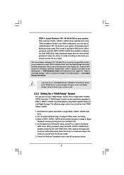
... set up system BIOS as step 1 of Intel Rapid Storage. Assemble the system and attach a single SATA / SATAII / SATA3 hard drive. 2. Finish the Windows® installation and install all necessary drivers. 7 STEP 4: Install Windows® XP / XP 64-bit OS on your system. After making a SATA / SATAII / SATA3 driver diskette and using RAID migration feature of page 6. Please refer to the document in the Support CD, "Guide to SATA Hard Disks Installation and RAID Configuration...
... set up system BIOS as step 1 of Intel Rapid Storage. Assemble the system and attach a single SATA / SATAII / SATA3 hard drive. 2. Finish the Windows® installation and install all necessary drivers. 7 STEP 4: Install Windows® XP / XP 64-bit OS on your system. After making a SATA / SATAII / SATA3 driver diskette and using RAID migration feature of page 6. Please refer to the document in the Support CD, "Guide to SATA Hard Disks Installation and RAID Configuration...


