
Intel Rapid Storage Guide
Page 12
... to select the physical disks. 6. Click F10 to enter the option ROM user interface. 2. Enable RAID in System BIOS Use the instructions included with your motherboard to enable RAID in the system BIOS, a RAID volume must be created, and the F6 installation method must be used to load the Intel®...
... to select the physical disks. 6. Click F10 to enter the option ROM user interface. 2. Enable RAID in System BIOS Use the instructions included with your motherboard to enable RAID in the system BIOS, a RAID volume must be created, and the F6 installation method must be used to load the Intel®...

Intel Smart Response Installation Guide
Page 1
... Acceleration" button on the GUI panel. 5. For the new version RST driver, please check our website for the latest information: http://www.asrock.com * Before you use RST function, you want to build RAID 0 or RAID 1 in the near future. It is not necessary to... use Enhanced or Maximized Mode. 6. Intel Smart Response Technology Installation Guide This motherboard supports Intel Smart Response Technology. For all required drivers, including RST storage driver version 10.5 or later. 2. After clicking OK button, SRT ...
... Acceleration" button on the GUI panel. 5. For the new version RST driver, please check our website for the latest information: http://www.asrock.com * Before you use RST function, you want to build RAID 0 or RAID 1 in the near future. It is not necessary to... use Enhanced or Maximized Mode. 6. Intel Smart Response Technology Installation Guide This motherboard supports Intel Smart Response Technology. For all required drivers, including RST storage driver version 10.5 or later. 2. After clicking OK button, SRT ...

User Manual
Page 2
... you discard the Lithium battery in California, USA, please follow the related regulations in Perchlorate Best Management Practices (BMP) regulations passed by ASRock. ASRock assumes no event shall ASRock, its directors, officers, employees, or agents be liable for any indirect, special, incidental, or consequential damages (including damages for... not be constructed as a commitment by the California Legislature. In no responsibility for a particular purpose. Products and corporate names appearing in this motherboard contains Perchlorate, a toxic substance controlled in advance.
... you discard the Lithium battery in California, USA, please follow the related regulations in Perchlorate Best Management Practices (BMP) regulations passed by ASRock. ASRock assumes no event shall ASRock, its directors, officers, employees, or agents be liable for any indirect, special, incidental, or consequential damages (including damages for... not be constructed as a commitment by the California Legislature. In no responsibility for a particular purpose. Products and corporate names appearing in this motherboard contains Perchlorate, a toxic substance controlled in advance.
User Manual
Page 3
Contents 1 Introduction 5 1.1 Package Contents 5 1.2 Specifications 6 1.3 Motherboard Layout 13 1.4 I/O Panel 14 2 Installation 16 2.1 Screw Holes 16 2.2 Pre-installation Precautions 16 2.3 CPU Installation 17 2.4 Installation of Heatsink and CPU fan ... Guide ... 24 2.8 CrossFireXTM, 3-Way CrossFireXTM and Quad CrossFireXTM Operation Guide 30 2.9 Dual Monitor and Surround Display Features 36 2.10 ASRock Smart Remote Installation Guide 39 2.11 ASRock XFast Charger Operation Guide 40 2.12 Jumpers Setup 41 2.13 Onboard Headers and Connectors 42 2.14 Smart Switches 49 2.15 Dr....
Contents 1 Introduction 5 1.1 Package Contents 5 1.2 Specifications 6 1.3 Motherboard Layout 13 1.4 I/O Panel 14 2 Installation 16 2.1 Screw Holes 16 2.2 Pre-installation Precautions 16 2.3 CPU Installation 17 2.4 Installation of Heatsink and CPU fan ... Guide ... 24 2.8 CrossFireXTM, 3-Way CrossFireXTM and Quad CrossFireXTM Operation Guide 30 2.9 Dual Monitor and Surround Display Features 36 2.10 ASRock Smart Remote Installation Guide 39 2.11 ASRock XFast Charger Operation Guide 40 2.12 Jumpers Setup 41 2.13 Onboard Headers and Connectors 42 2.14 Smart Switches 49 2.15 Dr....
User Manual
Page 5
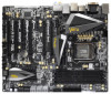
... 1 and 2 contain introduction of the Support CD. In case any modifications of this motherboard, please visit our website for purchasing ASRock Z68 Extreme7 Gen3 motherboard, a reliable motherboard produced under ASRock's consistently stringent quality control. www.asrock.com/support/index.asp 1.1 Package Contents ASRock Z68 Extreme7 Gen3 Motherboard (ATX Form Factor: 12.0-in x 9.6-in Storage Configuration to change without further notice...
... 1 and 2 contain introduction of the Support CD. In case any modifications of this motherboard, please visit our website for purchasing ASRock Z68 Extreme7 Gen3 motherboard, a reliable motherboard produced under ASRock's consistently stringent quality control. www.asrock.com/support/index.asp 1.1 Package Contents ASRock Z68 Extreme7 Gen3 Motherboard (ATX Form Factor: 12.0-in x 9.6-in Storage Configuration to change without further notice...
User Manual
Page 10
...: http://www.asrock.com 10 In addition, only PCIE2 slot supports up to 2133 and 1866. 4. Besides, with your system. HBR is supported under Windows® 7 64-bit / 7. For audio output, this motherboard supports both stereo and mono modes. This motherboard supports Dual Channel Memory Technology. Before you implement Dual Channel Memory Technology...
...: http://www.asrock.com 10 In addition, only PCIE2 slot supports up to 2133 and 1866. 4. Besides, with your system. HBR is supported under Windows® 7 64-bit / 7. For audio output, this motherboard supports both stereo and mono modes. This motherboard supports Dual Channel Memory Technology. Before you implement Dual Channel Memory Technology...
User Manual
Page 11
...or add new programs. Lower Latency in a few clicks without entering operating systems first like MS-DOS or Windows®. ASRock motherboards are assured to update system BIOS without preparing an additional floppy diskette or other complicated flash utility. With the ...Charger driver installed, you can easily recognize which includes below benefits. To use FAT32/16/12 file system. 12. ASRock website: http://www.asrock.com/Feature/ SmartView/index.asp 14. Traffic Shaping: You can easily enjoy the marvelous charging experience than before. Real...
...or add new programs. Lower Latency in a few clicks without entering operating systems first like MS-DOS or Windows®. ASRock motherboards are assured to update system BIOS without preparing an additional floppy diskette or other complicated flash utility. With the ...Charger driver installed, you can easily recognize which includes below benefits. To use FAT32/16/12 file system. 12. ASRock website: http://www.asrock.com/Feature/ SmartView/index.asp 14. Traffic Shaping: You can easily enjoy the marvelous charging experience than before. Real...
User Manual
Page 12
...portable audio devices, such like MP3 player or mobile phone to Intel's suggestion, the EuP ready power supply must meet EuP standard, an EuP ready motherboard and an EuP ready power supply are required. To meet the standard of the completed system shall be used. 22. 17. According to your PC..., even when the PC is detected, the system will automatically shutdown. ASRock On/Off Play Technology allows users to adopt three different CPU cooler types, Socket LGA 775, LGA 1155 and LGA 1156. While CPU overheat is...
...portable audio devices, such like MP3 player or mobile phone to Intel's suggestion, the EuP ready power supply must meet EuP standard, an EuP ready motherboard and an EuP ready power supply are required. To meet the standard of the completed system shall be used. 22. 17. According to your PC..., even when the PC is detected, the system will automatically shutdown. ASRock On/Off Play Technology allows users to adopt three different CPU cooler types, Socket LGA 775, LGA 1155 and LGA 1156. While CPU overheat is...
User Manual
Page 13
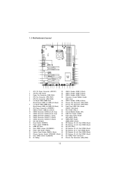
1.3 Motherboard Layout 1 24.4cm (9.6 in) USB 3.0 T: USB1 Top: B: ...Central/Bass LINE IN Center: REAR SPK Top: Center: FRONT LAN PHY RoHS Super I/O SLI/XFIRE_PWR1 CHA_FAN3 PCIE1 Z68 Extreme7 Gen3 PCIE2 PCIE3 XFast USB PCIE4 3-Way SLI PCI1 SATA3 6Gb/s ErP/EuP Ready Front USB 3.0 PCIE5 AUDIO CODEC ...FRONT_1394 CHA_FAN1 CHA_FAN2 1 USB8_9 1 CMOS Battery USB6_7 1 1 CIR1 USB4_5 1 USB2_3 1 USB3_5_6 SATA2_4_5 SATA2_2_3 SATA3_0_1 SATA3_A3_A4 SATA3_A1_A2 Intel Z68 RSTBTN 64Mb BIOS PWRBTN Dr. Debug Clr CMOS 1 CLRCMOS1 PLED1 1 SPEAKER1 1 PLED PWRBTN 1 HDLED RESET PANEL1 8 9...
1.3 Motherboard Layout 1 24.4cm (9.6 in) USB 3.0 T: USB1 Top: B: ...Central/Bass LINE IN Center: REAR SPK Top: Center: FRONT LAN PHY RoHS Super I/O SLI/XFIRE_PWR1 CHA_FAN3 PCIE1 Z68 Extreme7 Gen3 PCIE2 PCIE3 XFast USB PCIE4 3-Way SLI PCI1 SATA3 6Gb/s ErP/EuP Ready Front USB 3.0 PCIE5 AUDIO CODEC ...FRONT_1394 CHA_FAN1 CHA_FAN2 1 USB8_9 1 CMOS Battery USB6_7 1 1 CIR1 USB4_5 1 USB2_3 1 USB3_5_6 SATA2_4_5 SATA2_2_3 SATA3_0_1 SATA3_A3_A4 SATA3_A1_A2 Intel Z68 RSTBTN 64Mb BIOS PWRBTN Dr. Debug Clr CMOS 1 CLRCMOS1 PLED1 1 SPEAKER1 1 PLED PWRBTN 1 HDLED RESET PANEL1 8 9...
User Manual
Page 16
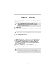
... an ATX form factor (12.0" x 9.6", 30.5 x 24.4 cm) motherboard. Do not over-tighten the screws! Before you uninstall any motherboard settings. 1. Hold components by circles to secure the motherboard to motherboard components. 2.1 Screw Holes Place screws into it on the carpet or the ...like. Failure to the motherboard, peripherals, and/or components. 16 Before you install the motherboard, study the configuration of the following precautions before installing or removing the motherboard. Also remember to unplug the power cord before you...
... an ATX form factor (12.0" x 9.6", 30.5 x 24.4 cm) motherboard. Do not over-tighten the screws! Before you uninstall any motherboard settings. 1. Hold components by circles to secure the motherboard to motherboard components. 2.1 Screw Holes Place screws into it on the carpet or the ...like. Failure to the motherboard, peripherals, and/or components. 16 Before you install the motherboard, study the configuration of the following precautions before installing or removing the motherboard. Also remember to unplug the power cord before you...
User Manual
Page 17
... there is any bent pin on the hook to fully open position at approximately 135 degrees. Otherwise, the CPU will be placed if returning the motherboard for after service. 17 Step 1-2. Step 1-3. Rotate the load plate to handle and avoid kicking off the PnP cap. 2. Remove PnP Cap (Pick and Place...
... there is any bent pin on the hook to fully open position at approximately 135 degrees. Otherwise, the CPU will be placed if returning the motherboard for after service. 17 Step 1-2. Step 1-3. Rotate the load plate to handle and avoid kicking off the PnP cap. 2. Remove PnP Cap (Pick and Place...
User Manual
Page 19
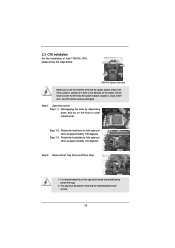
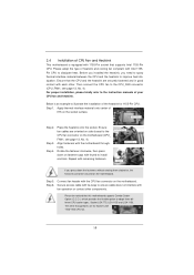
... (4 Places) If you need to spray thermal interface material between the CPU and the heatsink to improve heat dissipation. Ensure that this motherboard supports Combo Cooler Option (C.C.O.), which provides the flexible option to adopt three different CPU cooler types, Socket LGA 775, LGA 1155...4). Then connect the CPU fan to the CPU_FAN connector (CPU_FAN1, see page 13, No. 4). 2.4 Installation of CPU Fan and Heatsink This motherboard is an example to illustrate the installation of the heatsink for Socket LGA 1155/1156 CPU fan. 19 For proper installation, please kindly refer to...
... (4 Places) If you need to spray thermal interface material between the CPU and the heatsink to improve heat dissipation. Ensure that this motherboard supports Combo Cooler Option (C.C.O.), which provides the flexible option to adopt three different CPU cooler types, Socket LGA 775, LGA 1155...4). Then connect the CPU fan to the CPU_FAN connector (CPU_FAN1, see page 13, No. 4). 2.4 Installation of CPU Fan and Heatsink This motherboard is an example to illustrate the installation of the heatsink for Socket LGA 1155/1156 CPU fan. 19 For proper installation, please kindly refer to...
User Manual
Page 20
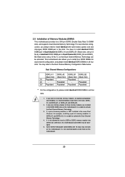
...DDR3_ A1 and DDR3_B1, or DDR3_A2 and DDR3_B2. 2. see p.13 No.7), so that Dual Channel Memory Technology can be damaged. 5. otherwise, this motherboard and DIMM may refer to the Dual Channel Memory Configuration Table below. Populated - (2) - If only one memory module or three memory ... (Black Slot) (Black Slot) (Black Slot) (1) Populated - Some DDR3 1GB double-sided DIMMs with 16 chips may not work on this motherboard. Black slots; For dual channel configuration, you want to install two memory modules, for example, installing a pair of Memory Modules (DIMM)...
...DDR3_ A1 and DDR3_B1, or DDR3_A2 and DDR3_B2. 2. see p.13 No.7), so that Dual Channel Memory Technology can be damaged. 5. otherwise, this motherboard and DIMM may refer to the Dual Channel Memory Configuration Table below. Populated - (2) - If only one memory module or three memory ... (Black Slot) (Black Slot) (Black Slot) (1) Populated - Some DDR3 1GB double-sided DIMMs with 16 chips may not work on this motherboard. Black slots; For dual channel configuration, you want to install two memory modules, for example, installing a pair of Memory Modules (DIMM)...
User Manual
Page 21
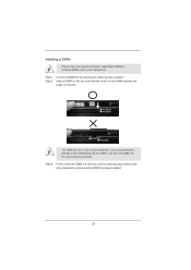
.... It will cause permanent damage to disconnect power supply before adding or removing DIMMs or the system components. Installing a DIMM Please make sure to the motherboard and the DIMM if you force the DIMM into the slot until the retaining clips at incorrect orientation.
.... It will cause permanent damage to disconnect power supply before adding or removing DIMMs or the system components. Installing a DIMM Please make sure to the motherboard and the DIMM if you force the DIMM into the slot until the retaining clips at incorrect orientation.
User Manual
Page 22
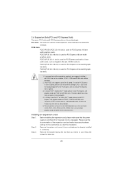
...Express slots on PCIE2 slot; PCIE2 (PCIE 3.0 x16 slot) is used for later use . If you intend to use . 22 in this motherboard. In CrossFireXTM mode or SLITM mode, please install PCI Express x16 graphics cards on PCIE1, PCIE4 and PCIE6 slots. In 3-Way CrossFireXTM or 3-... Express Gen 2 speed. 3. Therefore, both these two slots will run the PCI Express in a chassis). Please connect a chassis fan to motherboard chassis fan connector (CHA_FAN1, CHA_FAN2 or CHA_FAN3) when using multiple graphics cards for PCI Express x4 lane width graphics cards. Before installing the expansion...
...Express slots on PCIE2 slot; PCIE2 (PCIE 3.0 x16 slot) is used for later use . If you intend to use . 22 in this motherboard. In CrossFireXTM mode or SLITM mode, please install PCI Express x16 graphics cards on PCIE1, PCIE4 and PCIE6 slots. In 3-Way CrossFireXTM or 3-... Express Gen 2 speed. 3. Therefore, both these two slots will run the PCI Express in a chassis). Please connect a chassis fan to motherboard chassis fan connector (CHA_FAN1, CHA_FAN2 or CHA_FAN3) when using multiple graphics cards for PCI Express x4 lane width graphics cards. Before installing the expansion...
User Manual
Page 24
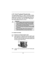
... (driver version 270.61 and later). Requirements 1. Download the driver from NVIDIA website (www.nvidia.com). 3. 2.7 SLITM, 3-Way SLITM and Quad SLITM Operation Guide This motherboard supports NVIDIA® SLITM, 3-Way SLITM and Quad SLITM (Scalable Link Interface) technology that allows you should have two identical SLITM-ready graphics cards that...
... (driver version 270.61 and later). Requirements 1. Download the driver from NVIDIA website (www.nvidia.com). 3. 2.7 SLITM, 3-Way SLITM and Quad SLITM Operation Guide This motherboard supports NVIDIA® SLITM, 3-Way SLITM and Quad SLITM (Scalable Link Interface) technology that allows you should have two identical SLITM-ready graphics cards that...
User Manual
Page 30
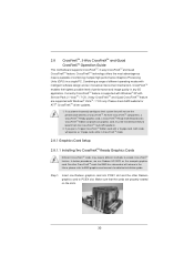
...enables the highest possible level of CrossFireXTM. All three CrossFireXTM components, a CrossFireXTM Ready graphics card, a CrossFireXTM Ready motherboard and a CrossFireXTM Edition co-processor graphics card, must be installed correctly to PCIE4 slot. 2.8 CrossFireXTM, 3-Way CrossFireXTM and ...Quad CrossFireXTM Operation Guide This motherboard supports CrossFireXTM, 3-way CrossFireXTM and Quad CrossFireXTM feature. If a customer incorrectly configures their system they will release...
...enables the highest possible level of CrossFireXTM. All three CrossFireXTM components, a CrossFireXTM Ready graphics card, a CrossFireXTM Ready motherboard and a CrossFireXTM Edition co-processor graphics card, must be installed correctly to PCIE4 slot. 2.8 CrossFireXTM, 3-Way CrossFireXTM and ...Quad CrossFireXTM Operation Guide This motherboard supports CrossFireXTM, 3-way CrossFireXTM and Quad CrossFireXTM feature. If a customer incorrectly configures their system they will release...
User Manual
Page 31
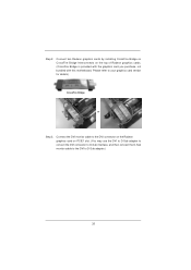
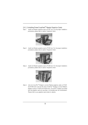
... the Radeon graphics card on the top of Radeon graphics cards. (CrossFire Bridge is provided with the graphics card you purchase, not bundled with this motherboard. Connect two Radeon graphics cards by installing CrossFire Bridge on CrossFire Bridge Interconnects on PCIE1 slot. (You may use the DVI to D-Sub adapter to...
... the Radeon graphics card on the top of Radeon graphics cards. (CrossFire Bridge is provided with the graphics card you purchase, not bundled with this motherboard. Connect two Radeon graphics cards by installing CrossFire Bridge on CrossFire Bridge Interconnects on PCIE1 slot. (You may use the DVI to D-Sub adapter to...
User Manual
Page 32
... Bridge to connect Radeon graphics cards on PCIE4 and PCIE6 slots. (CrossFireTM Bridge is provided with the graphics card you purchase, not bundled with this motherboard. Install one Radeon graphics card to PCIE6 slot. Step 4. 2.8.1.2 Installing Three CrossFireXTM-Ready Graphics Cards Step 1. For the proper installation procedures, please refer to section...
... Bridge to connect Radeon graphics cards on PCIE4 and PCIE6 slots. (CrossFireTM Bridge is provided with the graphics card you purchase, not bundled with this motherboard. Install one Radeon graphics card to PCIE6 slot. Step 4. 2.8.1.2 Installing Three CrossFireXTM-Ready Graphics Cards Step 1. For the proper installation procedures, please refer to section...
User Manual
Page 36
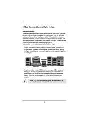
... D-Sub, DVI-D, HDMI and DisplayPort monitors cannot be enabled at the same time. 2.9 Dual Monitor and Surround Display Features Dual Monitor Feature This motherboard supports dual monitor feature. To enable dual monitor feature, please follow the below steps: 1. You can easily enjoy the benefits of dual... monitor feature without installing any add-on VGA card to this motherboard. Connect DVI-D monitor cable to DVI-D port on the I/O panel, connect D-Sub monitor cable to D-Sub port on the I/O panel, connect...
... D-Sub, DVI-D, HDMI and DisplayPort monitors cannot be enabled at the same time. 2.9 Dual Monitor and Surround Display Features Dual Monitor Feature This motherboard supports dual monitor feature. To enable dual monitor feature, please follow the below steps: 1. You can easily enjoy the benefits of dual... monitor feature without installing any add-on VGA card to this motherboard. Connect DVI-D monitor cable to DVI-D port on the I/O panel, connect D-Sub monitor cable to D-Sub port on the I/O panel, connect...


