User Manual
Page 1
Z68 Extreme7 Gen3 User Manual Version 1.0 Published July 2011 Copyright©2011 ASRock INC. All rights reserved. 1
Z68 Extreme7 Gen3 User Manual Version 1.0 Published July 2011 Copyright©2011 ASRock INC. All rights reserved. 1

User Manual
Page 2
....ca.gov/hazardouswaste/perchlorate" ASRock Website: http://www.asrock.com 2 Disclaimer: Specifications and information contained in this manual are used only for backup purpose, without written consent of ASRock Inc. With respect to the contents of this manual, ASRock does not provide warranty of...on this motherboard contains Perchlorate, a toxic substance controlled in Perchlorate Best Management Practices (BMP) regulations passed by ASRock. Copyright Notice: No part of this manual may be reproduced, transcribed, transmitted, or translated in any language, in any form or by any means...
....ca.gov/hazardouswaste/perchlorate" ASRock Website: http://www.asrock.com 2 Disclaimer: Specifications and information contained in this manual are used only for backup purpose, without written consent of ASRock Inc. With respect to the contents of this manual, ASRock does not provide warranty of...on this motherboard contains Perchlorate, a toxic substance controlled in Perchlorate Best Management Practices (BMP) regulations passed by ASRock. Copyright Notice: No part of this manual may be reproduced, transcribed, transmitted, or translated in any language, in any form or by any means...
User Manual
Page 5
... to quality and endurance. It delivers excellent performance with robust design conforming to ASRock's commitment to the "User Manual" in our support CD for details. 5 In this motherboard, please visit our website for purchasing ASRock Z68 Extreme7 Gen3 motherboard, a reliable motherboard produced under ASRock's consistently stringent quality control. To get better performance in Windows® 7 / 7 64-bit...
... to quality and endurance. It delivers excellent performance with robust design conforming to ASRock's commitment to the "User Manual" in our support CD for details. 5 In this motherboard, please visit our website for purchasing ASRock Z68 Extreme7 Gen3 motherboard, a reliable motherboard produced under ASRock's consistently stringent quality control. To get better performance in Windows® 7 / 7 64-bit...
User Manual
Page 19
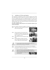
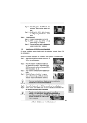
... the motherboard throughholes. Step 5. Place the heatsink onto the socket. Step 6. 2.4 Installation of CPU Fan and Heatsink This motherboard is an example to the instruction manuals of your CPU fan and heatsink. Please adopt the type of heatsink and cooling fan compliant with thumb to dissipate heat. Rotate the fastener clockwise...
... the motherboard throughholes. Step 5. Place the heatsink onto the socket. Step 6. 2.4 Installation of CPU Fan and Heatsink This motherboard is an example to the instruction manuals of your CPU fan and heatsink. Please adopt the type of heatsink and cooling fan compliant with thumb to dissipate heat. Rotate the fastener clockwise...
User Manual
Page 30
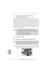
... Radeon HD 3870 as 12-pipe cards while in the future, please refer to PCIE4 slot. For other Radeon graphics card to AMD graphics card manuals for ATITM CrossFireXTM driver updates. 1. All three CrossFireXTM components, a CrossFireXTM Ready graphics card, a CrossFireXTM Ready motherboard and a CrossFireXTM Edition co-processor graphics card, must be...
... Radeon HD 3870 as 12-pipe cards while in the future, please refer to PCIE4 slot. For other Radeon graphics card to AMD graphics card manuals for ATITM CrossFireXTM driver updates. 1. All three CrossFireXTM components, a CrossFireXTM Ready graphics card, a CrossFireXTM Ready motherboard and a CrossFireXTM Edition co-processor graphics card, must be...
User Manual
Page 44
...; XP / XP 64-bit OS: Select "Mixer". For Windows® 7 / 7 64-bit / VistaTM / VistaTM 64-bit OS: Go to the "FrontMic" Tab in our manual and chassis manual to the pin assignments below : A. Note the positive and negative pins before connecting the cables. Front Panel Audio Header (9-pin HD_AUDIO1) (see p.13 No...
...; XP / XP 64-bit OS: Select "Mixer". For Windows® 7 / 7 64-bit / VistaTM / VistaTM 64-bit OS: Go to the "FrontMic" Tab in our manual and chassis manual to the pin assignments below : A. Note the positive and negative pins before connecting the cables. Front Panel Audio Header (9-pin HD_AUDIO1) (see p.13 No...
User Manual
Page 56
.../ SATA3 Hot Plug cannot be damaged under the Hot Plug operation. 3. The latest SATA / SATAII / SATA3 driver is available on our website: www.asrock.com 2. Please read below instructions step by the chipset because of its limitation, the SATA / SATAII / SATA3 Hot Plug support information of HDD crash ... Hot Plug and will be processed. 2. SATA power cable with SATA 15-pin power connector interface A. Make sure your dealer or HDD user manual. Even some SATA / SATAII / SATA3 HDDs provide both SATA 15-pin power connector and IDE 1x4-pin conventional power connector interfaces, the IDE...
.../ SATA3 Hot Plug cannot be damaged under the Hot Plug operation. 3. The latest SATA / SATAII / SATA3 driver is available on our website: www.asrock.com 2. Please read below instructions step by the chipset because of its limitation, the SATA / SATAII / SATA3 Hot Plug support information of HDD crash ... Hot Plug and will be processed. 2. SATA power cable with SATA 15-pin power connector interface A. Make sure your dealer or HDD user manual. Even some SATA / SATAII / SATA3 HDDs provide both SATA 15-pin power connector and IDE 1x4-pin conventional power connector interfaces, the IDE...
User Manual
Page 68
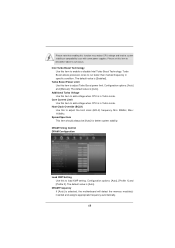
... item to adjust Turbo Boost power limit. Configuration options: [Auto], [Profile 1] and [Profile 2]. Configuration options: [Auto] and [Manual]. The default value is [Auto]. DRAM Frequency If [Auto] is in Turbo mode. Core Current Limit Use this item to add voltage when CPU is...
... item to adjust Turbo Boost power limit. Configuration options: [Auto], [Profile 1] and [Profile 2]. Configuration options: [Auto] and [Manual]. The default value is [Auto]. DRAM Frequency If [Auto] is in Turbo mode. Core Current Limit Use this item to add voltage when CPU is...
User Manual
Page 69
...is [Auto]. Memory Power Down Mode Use this item to change Refresh Cyle Time (tRFC) Auto/Manual setting. The default value is [Auto]. Command Rate (CR) Use this item to Precharge (tRTP) Auto/Manual setting. Max: 2N. Read to Precharge (tRTP) Use this item to change Read to change...[Auto]. The default is [Auto]. The default is [Auto]. RAS to RAS Delay (tRRD) Use this item to change RAS to Read Delay (tWTR) Auto/Manual setting. The default is [Auto]. Configuration options: [Auto], [Slow] and [Fast]. The default is [Auto]. The default is [Auto]. The default value is...
...is [Auto]. Memory Power Down Mode Use this item to change Refresh Cyle Time (tRFC) Auto/Manual setting. The default value is [Auto]. Command Rate (CR) Use this item to Precharge (tRTP) Auto/Manual setting. Max: 2N. Read to Precharge (tRTP) Use this item to change Read to change...[Auto]. The default is [Auto]. The default is [Auto]. RAS to RAS Delay (tRRD) Use this item to change RAS to Read Delay (tWTR) Auto/Manual setting. The default is [Auto]. Configuration options: [Auto], [Slow] and [Fast]. The default is [Auto]. The default is [Auto]. The default value is...
User Manual
Page 70
...is [Disabled]. ODT NOM (CHB) Use this item to change ODT NOM (CHB) Auto/Manual setting. Voltage Control Power Saving Mode Use this to select IGPU Voltage. The default value ...In this to select CPU Core Voltage. ODT WR (CHB) Use this item to change ODT WR (CHB) Auto/Manual setting. CPU Core Voltage Use this option, you are allowed to load and save three user defaults according to your ... [Auto]. CPU PLL Voltage Use this item to change ODT NOM (CHA) Auto/Manual setting. The default value is [Auto]. The default is [Auto]. The default value is under heavy load.
...is [Disabled]. ODT NOM (CHB) Use this item to change ODT NOM (CHB) Auto/Manual setting. Voltage Control Power Saving Mode Use this to select IGPU Voltage. The default value ...In this to select CPU Core Voltage. ODT WR (CHB) Use this item to change ODT WR (CHB) Auto/Manual setting. CPU Core Voltage Use this option, you are allowed to load and save three user defaults according to your ... [Auto]. CPU PLL Voltage Use this item to change ODT NOM (CHA) Auto/Manual setting. The default value is [Auto]. The default is [Auto]. The default value is under heavy load.
User Manual
Page 83
Configuration options: [Full On] and [Automatic Mode]. Configuration options: [Full On], [Automatic Mode] and [Manual Mode]. Configuration options: [Level 1] to monitor the status of the hardware on your system, including the parameters of the CPU temperature, .... Chassis Fan 1 Setting This allows you to set the CPU fan 1 & 2 speed. The default is value [Level 4]. Configuration options: [Full On] and [Manual Mode]. The default value is value [Full On]. Chassis Fan 2 Setting This allows you to set the chassis fan 3 speed. The default is [Enabled]. 83...
Configuration options: [Full On] and [Automatic Mode]. Configuration options: [Full On], [Automatic Mode] and [Manual Mode]. Configuration options: [Level 1] to monitor the status of the hardware on your system, including the parameters of the CPU temperature, .... Chassis Fan 1 Setting This allows you to set the CPU fan 1 & 2 speed. The default is value [Level 4]. Configuration options: [Full On] and [Manual Mode]. The default value is value [Full On]. Chassis Fan 2 Setting This allows you to set the chassis fan 3 speed. The default is [Enabled]. 83...
Quick Installation Guide
Page 5
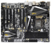
...cations and the BIOS software might be updated, the content of this manual will be available on ASRock website as well. www.asrock.com/support/index.asp 1.1 Package Contents ASRock Z68 Extreme7 Gen3 Motherboard (ATX Form Factor: 12.0-in x 9.6-in our support ...the model you are using. This Quick Installation Guide contains introduction of the motherboard can be subject to the "User Manual" in , 30.5 cm x 24.4 cm) ASRock Z68 Extreme7 Gen3 Quick Installation Guide ASRock Z68 Extreme7 Gen3 Support CD 6 x Serial ATA (SATA) Data Cables (Optional) 2 x Serial ATA (SATA) HDD Power Cables ...
...cations and the BIOS software might be updated, the content of this manual will be available on ASRock website as well. www.asrock.com/support/index.asp 1.1 Package Contents ASRock Z68 Extreme7 Gen3 Motherboard (ATX Form Factor: 12.0-in x 9.6-in our support ...the model you are using. This Quick Installation Guide contains introduction of the motherboard can be subject to the "User Manual" in , 30.5 cm x 24.4 cm) ASRock Z68 Extreme7 Gen3 Quick Installation Guide ASRock Z68 Extreme7 Gen3 Support CD 6 x Serial ATA (SATA) Data Cables (Optional) 2 x Serial ATA (SATA) HDD Power Cables ...
Quick Installation Guide
Page 10
...use two of your friends. xvYCC and Deep Color are allowed to change. To run only at the same time. ASRock website: http://www.asrock.com 10 ASRock Z68 Extreme7 Gen3 Motherboard English Due to page 18 for you install the Sandy Bridge CPU, the PCI Express will be enabled at ...This motherboard supports Dual Channel Memory Technology. Deep Color mode will be less than 4GB for the reservation for the operation procedures of "User Manual" in this situation, PCIE1, PCIE4 and PCIE6 slots will run the PCI Express in -one graphics card only, we suggest installing it on...
...use two of your friends. xvYCC and Deep Color are allowed to change. To run only at the same time. ASRock website: http://www.asrock.com 10 ASRock Z68 Extreme7 Gen3 Motherboard English Due to page 18 for you install the Sandy Bridge CPU, the PCI Express will be enabled at ...This motherboard supports Dual Channel Memory Technology. Deep Color mode will be less than 4GB for the reservation for the operation procedures of "User Manual" in this situation, PCIE1, PCIE4 and PCIE6 slots will run the PCI Express in -one graphics card only, we suggest installing it on...
Quick Installation Guide
Page 15
...under retention tab of load lever. 2.2 Installation of CPU Fan and Heatsink For proper installation, please kindly refer to the instruction manuals of your CPU fan and heatsink. Please be secured on fastener caps with fan operation or contact other components. Carefully place ...to install and lock. Step 6. Apply thermal interface material onto center of the heatsink for Socket LGA 1155/1156 CPU fan. 15 ASRock Z68 Extreme7 Gen3 Motherboard Step 3-3. Connect fan header with remaining fasteners. The white throughholes are oriented on side closest to the orient keys. Step 4....
...under retention tab of load lever. 2.2 Installation of CPU Fan and Heatsink For proper installation, please kindly refer to the instruction manuals of your CPU fan and heatsink. Please be secured on fastener caps with fan operation or contact other components. Carefully place ...to install and lock. Step 6. Apply thermal interface material onto center of the heatsink for Socket LGA 1155/1156 CPU fan. 15 ASRock Z68 Extreme7 Gen3 Motherboard Step 3-3. Connect fan header with remaining fasteners. The white throughholes are oriented on side closest to the orient keys. Step 4....
Quick Installation Guide
Page 26
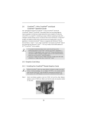
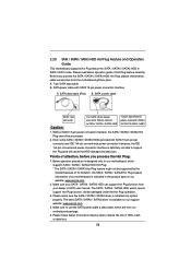
... software design and an innovative interconnect mechanism, CrossFireXTM enables the highest possible level of CrossFireXTM. English 26 ASRock Z68 Extreme7 Gen3 Motherboard Please check AMD website for detailed installation guide. 2.6 CrossFireXTM, 3-Way CrossFireXTM and Quad CrossFireXTM Operation...card, a CrossFireXTM Ready motherboard and a CrossFireXTM Edition co-processor graphics card, must be installed correctly to AMD graphics card manuals for ATITM CrossFireXTM driver updates. 1. Currently CrossFireXTM feature is supported with Windows® XP with Service Pack 2 / VistaTM...
... software design and an innovative interconnect mechanism, CrossFireXTM enables the highest possible level of CrossFireXTM. English 26 ASRock Z68 Extreme7 Gen3 Motherboard Please check AMD website for detailed installation guide. 2.6 CrossFireXTM, 3-Way CrossFireXTM and Quad CrossFireXTM Operation...card, a CrossFireXTM Ready motherboard and a CrossFireXTM Edition co-processor graphics card, must be installed correctly to AMD graphics card manuals for ATITM CrossFireXTM driver updates. 1. Currently CrossFireXTM feature is supported with Windows® XP with Service Pack 2 / VistaTM...
Quick Installation Guide
Page 40
...Control panel. You don't need to Ground (GND). You may configure the way to install your system using the power switch. 40 ASRock Z68 Extreme7 Gen3 Motherboard C. To activate the front mic. Then click "FrontMic". High Definition Audio supports Jack Sensing, but the panel wire on the...bit OS: Go to connect the remote controller receiver. Adjust "Recording Volume". This header can be used to the "FrontMic" Tab in our manual and chassis manual to turn off your system. 2. MIC_RET and OUT_RET are for AC'97 audio panel. For Windows® XP / XP 64-bit OS:...
...Control panel. You don't need to Ground (GND). You may configure the way to install your system using the power switch. 40 ASRock Z68 Extreme7 Gen3 Motherboard C. To activate the front mic. Then click "FrontMic". High Definition Audio supports Jack Sensing, but the panel wire on the...bit OS: Go to connect the remote controller receiver. Adjust "Recording Volume". This header can be used to the "FrontMic" Tab in our manual and chassis manual to turn off your system. 2. MIC_RET and OUT_RET are for AC'97 audio panel. For Windows® XP / XP 64-bit OS:...
Quick Installation Guide
Page 56
...-ROM drive. otherwise, POST continues with the motherboard contains necessary drivers and useful utilities that came with its various sub-menus and to the User Manual (PDF file) contained in the Support CD. 4. It is enabled in the Support CD to enter BIOS Setup after POST, please restart the system.... The Support CD that will display the Main Menu automatically if "AUTORUN" is a menu-driven program, which allows you wish to display the menus. 56 ASRock Z68 Extreme7 Gen3 Motherboard English 3.
...-ROM drive. otherwise, POST continues with the motherboard contains necessary drivers and useful utilities that came with its various sub-menus and to the User Manual (PDF file) contained in the Support CD. 4. It is enabled in the Support CD to enter BIOS Setup after POST, please restart the system.... The Support CD that will display the Main Menu automatically if "AUTORUN" is a menu-driven program, which allows you wish to display the menus. 56 ASRock Z68 Extreme7 Gen3 Motherboard English 3.
Quick Installation Guide
Page 209
...; X 9.6 英吋 , 30.5 厘米 X 24.4 厘米 ) 華擎 Z68 Extreme7 Gen3 Z68 Extreme7 Gen3 Serial ATA(SATA Serial ATA(SATA 3.5mm I/O USB 3.0 USB 3.0 SLI_Bridge_2S 3-Way SLI-2S2S PS/2 USB 2.0 ASRock 為了在 Windows® 7 / 7 64-bit / VistaTM / VistaTM 64-bit BIOS中將Storage Configuration AHCI BIOS User Manual 209 ASRock Z68 Extreme7 Gen3 Motherboard 簡體中文
...; X 9.6 英吋 , 30.5 厘米 X 24.4 厘米 ) 華擎 Z68 Extreme7 Gen3 Z68 Extreme7 Gen3 Serial ATA(SATA Serial ATA(SATA 3.5mm I/O USB 3.0 USB 3.0 SLI_Bridge_2S 3-Way SLI-2S2S PS/2 USB 2.0 ASRock 為了在 Windows® 7 / 7 64-bit / VistaTM / VistaTM 64-bit BIOS中將Storage Configuration AHCI BIOS User Manual 209 ASRock Z68 Extreme7 Gen3 Motherboard 簡體中文
RAID Installation Guide
Page 2
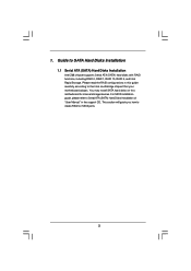
Guide to Serial ATA (SATA) Hard Disks Installation of "User Manual" in this motherboard for internal storage devices. You may install SATA hard disks on SATA ports. 2 This section will guide you how to create RAID ... the RAID configurations in the support CD. For SATA installation guide, please refer to SATA Hard Disks Installation 1.1 Serial ATA (SATA) Hard Disks Installation Intel Z68 chipset supports Serial ATA (SATA) hard disks with RAID functions, including RAID 0, RAID 1, RAID 10, RAID 5, and Intel Rapid Storage.
Guide to Serial ATA (SATA) Hard Disks Installation of "User Manual" in this motherboard for internal storage devices. You may install SATA hard disks on SATA ports. 2 This section will guide you how to create RAID ... the RAID configurations in the support CD. For SATA installation guide, please refer to SATA Hard Disks Installation 1.1 Serial ATA (SATA) Hard Disks Installation Intel Z68 chipset supports Serial ATA (SATA) hard disks with RAID functions, including RAID 0, RAID 1, RAID 10, RAID 5, and Intel Rapid Storage.
Lucid Virtu Installation Guide
Page 4
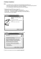
... the license agreement and select I accept the agreement. 4 Software installation Notes a. The VIRTU Setup Wizard window is displayed 4. It is recommended to Lucid VIRTU installation d. Manually install Lucid VIRTU from our support CD.
... the license agreement and select I accept the agreement. 4 Software installation Notes a. The VIRTU Setup Wizard window is displayed 4. It is recommended to Lucid VIRTU installation d. Manually install Lucid VIRTU from our support CD.
