User Manual
Page 3
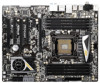
Contents 1 Introduction 5 1.1 Package Contents 5 1.2 Specifications 6 1.3 Motherboard Layout (X79 Extreme6/GB / X79 Extreme6 12 1.4 I/O Panel (X79 Extreme6/GB / X79 Extreme6 13 1.5 ASRock Game Blaster (X79 Extreme6/GB 15 2 Installation 18 2.1 Screw Holes 18 2.2 Pre-installation Precautions 18 2.3 CPU Installation ...Plug and Hot Swap Functions for SATA3 HDDs .... 63 2.20 SATA / SATAII / SATA3 HDD Hot Plug Feature and Operation Guide 64 2.21 Driver Installation Guide 66 2.22 Installing Windows® 7 / 7 64-bit / VistaTM / VistaTM 64-bit With RAID Functions 66 2.23 Installing ...
Contents 1 Introduction 5 1.1 Package Contents 5 1.2 Specifications 6 1.3 Motherboard Layout (X79 Extreme6/GB / X79 Extreme6 12 1.4 I/O Panel (X79 Extreme6/GB / X79 Extreme6 13 1.5 ASRock Game Blaster (X79 Extreme6/GB 15 2 Installation 18 2.1 Screw Holes 18 2.2 Pre-installation Precautions 18 2.3 CPU Installation ...Plug and Hot Swap Functions for SATA3 HDDs .... 63 2.20 SATA / SATAII / SATA3 HDD Hot Plug Feature and Operation Guide 64 2.21 Driver Installation Guide 66 2.22 Installing Windows® 7 / 7 64-bit / VistaTM / VistaTM 64-bit With RAID Functions 66 2.23 Installing ...
User Manual
Page 4
... Without RAID Functions 67 2.23.2 Installing Windows® 7 / 7 64-bit / VistaTM / VistaTM 64-bit Without RAID Functions 68 2.24 Teaming Function Operation Guide (X79 Extreme6/GB 69 2.25 Untied Overclocking Technology 72 3 UEFI SETUP UTILITY 73 3.1 Introduction 73 3.1.1 UEFI Menu Bar 73 3.1.2 Navigation Keys 74 3.2 Main Screen 74 3.3 OC ... Screen 93 3.7 Security Screen 94 3.8 Exit Screen 95 4 Software Support 96 4.1 Install Operating System 96 4.2 Support CD Information 96 4.2.1 Running Support CD 96 4.2.2 Drivers Menu 96 4.2.3 Utilities Menu 96 4.2.4 Contact Information 96 4
... Without RAID Functions 67 2.23.2 Installing Windows® 7 / 7 64-bit / VistaTM / VistaTM 64-bit Without RAID Functions 68 2.24 Teaming Function Operation Guide (X79 Extreme6/GB 69 2.25 Untied Overclocking Technology 72 3 UEFI SETUP UTILITY 73 3.1 Introduction 73 3.1.1 UEFI Menu Bar 73 3.1.2 Navigation Keys 74 3.2 Main Screen 74 3.3 OC ... Screen 93 3.7 Security Screen 94 3.8 Exit Screen 95 4 Software Support 96 4.1 Install Operating System 96 4.2 Support CD Information 96 4.2.1 Running Support CD 96 4.2.2 Drivers Menu 96 4.2.3 Utilities Menu 96 4.2.4 Contact Information 96 4
User Manual
Page 8
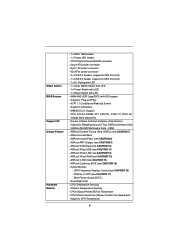
...LED - 1 x Power Switch with LED - 1 x Reset Switch with LED - 64Mb AMI UEFI Legal BIOS with GUI support - ASRock XFast RAM (see CAUTION 11) - CPU/Chassis Quiet Fan (Allows Chassis Fan Speed AutoAdjust by CPU Temperature) 8 Smart Switch BIOS Feature...Up Events - SMBIOS 2.3.1 Support - Drivers, Utilities, AntiVirus Software (Trial Version), CyberLink MediaEspresso 6.5 Trial, ASRock Software Suite (ASRock MAGIX Multimedia Suite - ASRock Extreme Tuning Utility (AXTU) (see CAUTION 10) - ASRock SmartView (see CAUTION 7) - ASRock XFast LAN (see CAUTION 14) - ASRock X-FAN (see CAUTION 12) -...
...LED - 1 x Power Switch with LED - 1 x Reset Switch with LED - 64Mb AMI UEFI Legal BIOS with GUI support - ASRock XFast RAM (see CAUTION 11) - CPU/Chassis Quiet Fan (Allows Chassis Fan Speed AutoAdjust by CPU Temperature) 8 Smart Switch BIOS Feature...Up Events - SMBIOS 2.3.1 Support - Drivers, Utilities, AntiVirus Software (Trial Version), CyberLink MediaEspresso 6.5 Trial, ASRock Software Suite (ASRock MAGIX Multimedia Suite - ASRock Extreme Tuning Utility (AXTU) (see CAUTION 10) - ASRock SmartView (see CAUTION 7) - ASRock XFast LAN (see CAUTION 14) - ASRock X-FAN (see CAUTION 12) -...
User Manual
Page 10
...to ne-tune different system functions in Flash ROM. With APP Charger driver installed, you to quickly charge many Apple devices simultaneously and even supports continuous charging when your computer and up to access ASRock Instant Flash. In Overclocking, you are allowed to overclock CPU frequency ... Just launch this utility, you to RAM (S3), hibernation mode (S4) or power off (S5). Simply install the APP Charger driver, it with your friends. ASRock SmartView, a new function for internet browsers, is the smart start page for IE that combines your most visited web sites, your ...
...to ne-tune different system functions in Flash ROM. With APP Charger driver installed, you to quickly charge many Apple devices simultaneously and even supports continuous charging when your computer and up to access ASRock Instant Flash. In Overclocking, you are allowed to overclock CPU frequency ... Just launch this utility, you to RAM (S3), hibernation mode (S4) or power off (S5). Simply install the APP Charger driver, it with your friends. ASRock SmartView, a new function for internet browsers, is the smart start page for IE that combines your most visited web sites, your ...

User Manual
Page 21
... 12, No. 8). Apply Thermal Interface Material Step 2. Ensure fan cables are securely fastened and in good contact with fan operation or contact other . Use a screw driver to the CPU_FAN connector (CPU_FAN1, see page 12, No. 9 or CPU_FAN2, see page 12, No. 8). Step 5. Connect fan header with 2011-Pin socket that the...
... 12, No. 8). Apply Thermal Interface Material Step 2. Ensure fan cables are securely fastened and in good contact with fan operation or contact other . Use a screw driver to the CPU_FAN connector (CPU_FAN1, see page 12, No. 9 or CPU_FAN2, see page 12, No. 8). Step 5. Connect fan header with 2011-Pin socket that the...

User Manual
Page 25
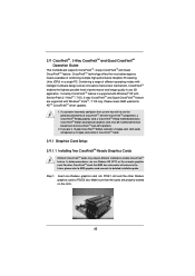
...ASRock Game Blaster Installation Guide (X79 Extreme6/GB) 2.7.1 ASRock Game Blaster and Driver Installation Step 1. ASRock Game Blaster VGA card VGA card 25 Step 5. Please refer to the chassis with screws. Step 4. Step 6. Align the card connector with screws. Step 2. Fasten the card to the "Expansion Slots" section then insert ASRock... Game Blaster into PCIE4 slot. In order to avoid mechanical conflict, please fasten your VGA cards and ASRock Game Blaster to the chassis with the slot and press &#...
...ASRock Game Blaster Installation Guide (X79 Extreme6/GB) 2.7.1 ASRock Game Blaster and Driver Installation Step 1. ASRock Game Blaster VGA card VGA card 25 Step 5. Please refer to the chassis with screws. Step 4. Step 6. Align the card connector with screws. Step 2. Fasten the card to the "Expansion Slots" section then insert ASRock... Game Blaster into PCIE4 slot. In order to avoid mechanical conflict, please fasten your VGA cards and ASRock Game Blaster to the chassis with the slot and press &#...

User Manual
Page 26
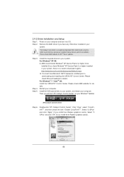
Step 3. Step 4. Restart your computer for ASRock Game Blaster to use Windows® VistaTM 32-bit / 64-bit or Windows® 7 32-bit / 64-bit. Follow the step by step driver setup directions. ASRock Game Blaster is not supported under Windows® XP / XP 64-bit. Please make sure to take effect. 26
Step 3. Step 4. Restart your computer for ASRock Game Blaster to use Windows® VistaTM 32-bit / 64-bit or Windows® 7 32-bit / 64-bit. Follow the step by step driver setup directions. ASRock Game Blaster is not supported under Windows® XP / XP 64-bit. Please make sure to take effect. 26

User Manual
Page 37
... supply unit (PSU) can provide at least the minimum power required by your graphics card driver supports NVIDIA® SLITM technology (driver version 280.41 and later). Make sure that are NVIDIA® certified. Download the driver from NVIDIA website (www.nvidia.com). 3. It is recommended to the PCI Express graphics...
... supply unit (PSU) can provide at least the minimum power required by your graphics card driver supports NVIDIA® SLITM technology (driver version 280.41 and later). Make sure that are NVIDIA® certified. Download the driver from NVIDIA website (www.nvidia.com). 3. It is recommended to the PCI Express graphics...
User Manual
Page 40
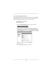
... SLI and PhysX configuration. And click Apply. Reboot your Windows® taskbar. D. Double-click NVIDIA Settings icon on your system. 2.8.2 Driver Installation and Setup Install the graphics card drivers to enable the multi-GPU feature. For Windows® XP / XP 64-bit OS: (For SLITM mode only) A. Please follow the...
... SLI and PhysX configuration. And click Apply. Reboot your Windows® taskbar. D. Double-click NVIDIA Settings icon on your system. 2.8.2 Driver Installation and Setup Install the graphics card drivers to enable the multi-GPU feature. For Windows® XP / XP 64-bit OS: (For SLITM mode only) A. Please follow the...
User Manual
Page 43
... Ready graphics card, a CrossFireXTM Ready motherboard and a CrossFireXTM Edition co-processor graphics card, must be installed correctly to AMD graphics card manuals for ATITM CrossFireXTM driver updates. 1. Step 1. In below procedures, we use Radeon HD 5770 as 12-pipe cards while in the future, please refer to benefit from the...
... Ready graphics card, a CrossFireXTM Ready motherboard and a CrossFireXTM Edition co-processor graphics card, must be installed correctly to AMD graphics card manuals for ATITM CrossFireXTM driver updates. 1. Step 1. In below procedures, we use Radeon HD 5770 as 12-pipe cards while in the future, please refer to benefit from the...
User Manual
Page 46
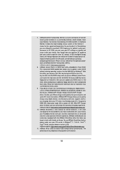
...® XP Service Pack 2 or higher installed in your system. Power on your computer. Step 2. Please check Microsoft website for ATITM driver updates. The Catalyst Uninstaller is no need to installation. For Windows® 7 / VistaTM OS: Install the CATALYST Control Center. Please check...the CATALYST Control Center. For Windows® XP OS: A. Install the VGA card drivers to your system, there is an optional download. 2.9.2 Driver Installation and Setup Step 1. Install the required drivers to your system, and restart your Windows® taskbar. You must have any ...
...® XP Service Pack 2 or higher installed in your system. Power on your computer. Step 2. Please check Microsoft website for ATITM driver updates. The Catalyst Uninstaller is no need to installation. For Windows® 7 / VistaTM OS: Install the CATALYST Control Center. Please check...the CATALYST Control Center. For Windows® XP OS: A. Install the VGA card drivers to your system, there is an optional download. 2.9.2 Driver Installation and Setup Step 1. Install the required drivers to your system, and restart your Windows® taskbar. You must have any ...

User Manual
Page 60
... module specific) ACPI module initialization CSM initialization Reserved for future AMI DXE codes OEM DXE initialization codes Boot Device Selection (BDS) phase is started Driver connecting is started PCI Bus initialization is started PCI Bus Hot Plug Controller Initialization PCI Bus Enumeration PCI Bus Request Resources PCI Bus Assign Resources...
... module specific) ACPI module initialization CSM initialization Reserved for future AMI DXE codes OEM DXE initialization codes Boot Device Selection (BDS) phase is started Driver connecting is started PCI Bus initialization is started PCI Bus Hot Plug Controller Initialization PCI Bus Enumeration PCI Bus Request Resources PCI Bus Assign Resources...

User Manual
Page 64
... or HDD user manual. A. 7-pin SATA data cable B. SATA data cable (Red) B. Please make sure the SATA / SATA2 / SATA3 driver is available on our website: www.asrock.com 2. The SATA / SATA2 / SATA3 HDD, which cannot support Hot Plug function, will cause the HDD damage and data loss. Please read... IDE 1x4-pin conventional power connector interface is designed only for SATA / SATA2 / SATA3 HDD in the product spec on our support website: www.asrock.com 4. Points of attention, before you process the SATA / SATA2 / SATA3 HDD Hot Plug, please check below operation guide of HDD crash or...
... or HDD user manual. A. 7-pin SATA data cable B. SATA data cable (Red) B. Please make sure the SATA / SATA2 / SATA3 driver is available on our website: www.asrock.com 2. The SATA / SATA2 / SATA3 HDD, which cannot support Hot Plug function, will cause the HDD damage and data loss. Please read... IDE 1x4-pin conventional power connector interface is designed only for SATA / SATA2 / SATA3 HDD in the product spec on our support website: www.asrock.com 4. Points of attention, before you process the SATA / SATA2 / SATA3 HDD Hot Plug, please check below operation guide of HDD crash or...
User Manual
Page 66
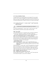
...non Intel® SATA2 / SATA3 port. B. Set the option "ASMedia SATA3 Bootable" to install OS on the support CD driver page. Intel® RAID drivers are located in the folder at the following path of our Support CD: 32 bit: ..\i386\Win7_Vista_Intel_v3.0.0.1112 64-bit: ... 64-bit OS on your optical drive first. Before you start to configure the RAID function, you want to install those required drivers. STEP 2: Use "RAID Installation Guide" to your system. A. Enter UEFI SETUP UTILITY Advanced screen Storage Configuration. Insert the Windows®...
...non Intel® SATA2 / SATA3 port. B. Set the option "ASMedia SATA3 Bootable" to install OS on the support CD driver page. Intel® RAID drivers are located in the folder at the following path of our Support CD: 32 bit: ..\i386\Win7_Vista_Intel_v3.0.0.1112 64-bit: ... 64-bit OS on your optical drive first. Before you start to configure the RAID function, you want to install those required drivers. STEP 2: Use "RAID Installation Guide" to your system. A. Enter UEFI SETUP UTILITY Advanced screen Storage Configuration. Insert the Windows®...

User Manual
Page 67
... the following path: .. \ Intel Rapid Storage Information If you want to make the USB flash driver disk, please copy above Intel® RAID drivers from our Support CD to your USB flash, and then load drivers from the USB flash disk. 2.23 Installing Windows® 7 / 7 64-bit / VistaTM / VistaTM 64...
... the following path: .. \ Intel Rapid Storage Information If you want to make the USB flash driver disk, please copy above Intel® RAID drivers from our Support CD to your USB flash, and then load drivers from the USB flash disk. 2.23 Installing Windows® 7 / 7 64-bit / VistaTM / VistaTM 64...
User Manual
Page 69
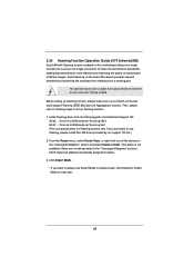
...our support CD link.) 2. 2.24 Teaming Function Operation Guide (X79 Extreme6/GB) Dual LAN with Teaming enabled. The speed of transmission is subject to teams. 3. Before setting up Teaming function. 1. This option is a special driver for twice the transmission bandwidth, making data transmission more effective ..." sections, which means all adapters are no devices listed in the "Unassigned Adapters" section and select Create a Team. Install Teaming driver from a failed port to act as one of distant images. From the Teams menu, select Create Team, or right-click one single...
...our support CD link.) 2. 2.24 Teaming Function Operation Guide (X79 Extreme6/GB) Dual LAN with Teaming enabled. The speed of transmission is subject to teams. 3. Before setting up Teaming function. 1. This option is a special driver for twice the transmission bandwidth, making data transmission more effective ..." sections, which means all adapters are no devices listed in the "Unassigned Adapters" section and select Create a Team. Install Teaming driver from a failed port to act as one of distant images. From the Teams menu, select Create Team, or right-click one single...
User Manual
Page 70
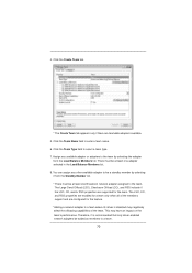
...;eld to a team. 70 There must be added as members to enter a team name. 6. Assign any other available adapter to a team where its driver is recommended that only driver-enabled network adapters be at least one Broadcom network adapter assigned to the team. The LSO, CO, and RSS properties are enabled for...
...;eld to a team. 70 There must be added as members to enter a team name. 6. Assign any other available adapter to a team where its driver is recommended that only driver-enabled network adapters be at least one Broadcom network adapter assigned to the team. The LSO, CO, and RSS properties are enabled for...
User Manual
Page 71
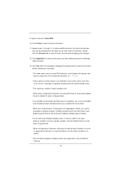
... Balancing and Failover and SLB (Auto-Fallback Disable) types of team members is 8. * When team configuration has been correctly performed, a virtual team adapter driver is recommended to connect team members to define additional teams. As teams are supported or fully certified for Team MTU. 10...
... Balancing and Failover and SLB (Auto-Fallback Disable) types of team members is 8. * When team configuration has been correctly performed, a virtual team adapter driver is recommended to connect team members to define additional teams. As teams are supported or fully certified for Team MTU. 10...
User Manual
Page 96
... To begin using the support CD, insert the CD into your OS documentation for more about ASRock, welcome to know more information. 4.2 Support CD Information The Support CD that came with the motherboard contains necessary drivers and useful utilities that the motherboard supports. Click on the file "ASSETUP.EXE" from the...
... To begin using the support CD, insert the CD into your OS documentation for more about ASRock, welcome to know more information. 4.2 Support CD Information The Support CD that came with the motherboard contains necessary drivers and useful utilities that the motherboard supports. Click on the file "ASSETUP.EXE" from the...
User Manual
Page 98
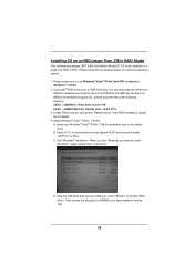
...bit (with SP1 or above) or Windows® 7 64-bit. 2. Copy Intel® RAID drivers into a USB flash disk OR copy the file from ASRock motherboard support CD. (please copy the files under following directory: 32 bit: ..\i386\Win7_Vista_Intel_v3.0.0....1112 64-bit: ..\AMD64\Win7-64_Vista64_Intel_v3.0.0.1112 3. Install Windows® VistaTM 64-bit / 7 64-bit: A. D. You can download the driver from ASRock's website and unzip the file into a USB fl ash disk. B. Start Windows® Installation. Please make sure to install the ...
...bit (with SP1 or above) or Windows® 7 64-bit. 2. Copy Intel® RAID drivers into a USB flash disk OR copy the file from ASRock motherboard support CD. (please copy the files under following directory: 32 bit: ..\i386\Win7_Vista_Intel_v3.0.0....1112 64-bit: ..\AMD64\Win7-64_Vista64_Intel_v3.0.0.1112 3. Install Windows® VistaTM 64-bit / 7 64-bit: A. D. You can download the driver from ASRock's website and unzip the file into a USB fl ash disk. B. Start Windows® Installation. Please make sure to install the ...


