User Manual
Page 10
.... Please be noted that helps you can press the key during the POST or the key to enter into Standby mode (S1), Suspend to 40% faster than before. If you can update your browser version is an all-in a user-friendly interface, which includes Hardware Monitor, Fan Control, Overclocking, OC DNA and IES. To use FAT32/16/12 file system. 9. The performance...
.... Please be noted that helps you can press the key during the POST or the key to enter into Standby mode (S1), Suspend to 40% faster than before. If you can update your browser version is an all-in a user-friendly interface, which includes Hardware Monitor, Fan Control, Overclocking, OC DNA and IES. To use FAT32/16/12 file system. 9. The performance...

User Manual
Page 12
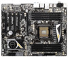
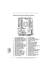
... 26 1 Power Fan Connector (PWR_FAN1) 26 Reset Switch (RSTBTN1) 2 240-pin DDR3 DIMM Slot (DDR3_A1, Black) 27 Power Switch (PWRBTN1) 3 240-pin DDR3 DIMM Slot (DDR3_A2, Black) 28 Chassis Speaker Header (SPEAKER1, Black) 4 240-pin DDR3 DIMM Slot (DDR3_B1, Black) 29 System Panel Header (PANEL1, Black) 5 240-pin DDR3 DIMM Slot (DDR3_B2, Black) 30 Power LED Header (PLED1) 6 ATX 12V Power Connector (ATX12V1) 31 Dr. Debug 7 2011-Pin CPU Socket 32 Chassis Fan Connector (CHA_FAN3) 8 CPU Fan Connector (CPU_FAN2) 33 Clear CMOS Jumper (CLRCMOS1) 9 CPU Fan Connector (CPU_FAN1) 34 USB 2.0 Header...
... 26 1 Power Fan Connector (PWR_FAN1) 26 Reset Switch (RSTBTN1) 2 240-pin DDR3 DIMM Slot (DDR3_A1, Black) 27 Power Switch (PWRBTN1) 3 240-pin DDR3 DIMM Slot (DDR3_A2, Black) 28 Chassis Speaker Header (SPEAKER1, Black) 4 240-pin DDR3 DIMM Slot (DDR3_B1, Black) 29 System Panel Header (PANEL1, Black) 5 240-pin DDR3 DIMM Slot (DDR3_B2, Black) 30 Power LED Header (PLED1) 6 ATX 12V Power Connector (ATX12V1) 31 Dr. Debug 7 2011-Pin CPU Socket 32 Chassis Fan Connector (CHA_FAN3) 8 CPU Fan Connector (CPU_FAN2) 33 Clear CMOS Jumper (CLRCMOS1) 9 CPU Fan Connector (CPU_FAN1) 34 USB 2.0 Header...
User Manual
Page 46
..." on your computer and boot into OS. Remove the AMD driver if you have any previously installed Catalyst drivers prior to be installed (If you install two Radeon graphics cards). Step 5. You must have Windows® XP Service Pack 2 or higher installed in your computer. Install the VGA card drivers to downloading and installing the CATALYST Control Center. AMD recommends Windows® XP Service Pack 2 or higher to installation. Please check Microsoft website for...
..." on your computer and boot into OS. Remove the AMD driver if you have any previously installed Catalyst drivers prior to be installed (If you install two Radeon graphics cards). Step 5. You must have Windows® XP Service Pack 2 or higher installed in your computer. Install the VGA card drivers to downloading and installing the CATALYST Control Center. AMD recommends Windows® XP Service Pack 2 or higher to installation. Please check Microsoft website for...

User Manual
Page 58
... codes. Application Processor(s) (AP) initialization CPU post-memory initialization. System Management Mode (SMM) initialization 58 2.15 Dr. Debug Dr. Debug is used Power on. Memory presence detection Memory initialization. Please see the diagrams below for future AMI SEC error codes Microcode not found Microcode not loaded PEI Core is started Pre-memory CPU initialization is started Pre-memory CPU initialization (CPU module specific) Pre-memory CPU initialization (CPU module specific) Pre-memory CPU initialization (CPU module...
... codes. Application Processor(s) (AP) initialization CPU post-memory initialization. System Management Mode (SMM) initialization 58 2.15 Dr. Debug Dr. Debug is used Power on. Memory presence detection Memory initialization. Please see the diagrams below for future AMI SEC error codes Microcode not found Microcode not loaded PEI Core is started Pre-memory CPU initialization is started Pre-memory CPU initialization (CPU module specific) Pre-memory CPU initialization (CPU module specific) Pre-memory CPU initialization (CPU module...
User Manual
Page 66
.... Enter UEFI SETUP UTILITY Advanced screen Storage Configuration. B. Set the option "ASMedia SATA3 Bootable" to [Yes] for Intel® SATA2 / SATA3 ports. Intel® RAID drivers are located in the following path: .. \ RAID Installation Guide STEP 3: Install Windows® 7 / 7 64-bit / VistaTM / VistaTM 64-bit OS on your system. Please follow below steps. The optical drive should be auto-detected and listed on the support CD driver page. If you install can be installed...
.... Enter UEFI SETUP UTILITY Advanced screen Storage Configuration. B. Set the option "ASMedia SATA3 Bootable" to [Yes] for Intel® SATA2 / SATA3 ports. Intel® RAID drivers are located in the following path: .. \ RAID Installation Guide STEP 3: Install Windows® 7 / 7 64-bit / VistaTM / VistaTM 64-bit OS on your system. Please follow below steps. The optical drive should be auto-detected and listed on the support CD driver page. If you install can be installed...

User Manual
Page 90
...enter OS. [UEFI Setup Only] - 3.4.7 USB Configuration USB 2.0 Controller Use this option to select legacy support for USB devices. There are connected. [Disabled] - Enables legacy support if USB devices are four configuration options: [Enabled], [Auto], [Disabled] and [UEFI Setup Only]. If you have USB compatibility issue, it is [Disabled]. 90 USB devices are not allowed to use of USB 2.0 controller. The default value is [Enabled]. Enables support for USB 3.0 devices. USB devices are allowed to use of these four options: [Enabled] - The default value is [Enabled...
...enter OS. [UEFI Setup Only] - 3.4.7 USB Configuration USB 2.0 Controller Use this option to select legacy support for USB devices. There are connected. [Disabled] - Enables legacy support if USB devices are four configuration options: [Enabled], [Auto], [Disabled] and [UEFI Setup Only]. If you have USB compatibility issue, it is [Disabled]. 90 USB devices are not allowed to use of USB 2.0 controller. The default value is [Enabled]. Enables support for USB 3.0 devices. USB devices are allowed to use of these four options: [Enabled] - The default value is [Enabled...
User Manual
Page 92
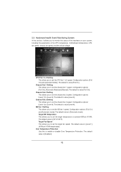
... of the CPU temperature, motherboard temperature, CPU fan speed, chassis fan speed, and the critical voltage. The default is [50oC/122oF]. Configuration options: [Level 1] to [Level 4]. The default value is value [Level 4]. 3.5 Hardware Health Event Monitoring Screen In this to enable or disable Over Temperature Protection. Configuration options: [Full On], [Automatic Mode] and [Manual]. Chassis Fan 2 Setting This allows you to set the SB fan 1 speed. SB Fan 1 Setting This allows you to set the chassis fan 2 speed. The default is...
... of the CPU temperature, motherboard temperature, CPU fan speed, chassis fan speed, and the critical voltage. The default is [50oC/122oF]. Configuration options: [Level 1] to [Level 4]. The default value is value [Level 4]. 3.5 Hardware Health Event Monitoring Screen In this to enable or disable Over Temperature Protection. Configuration options: [Full On], [Automatic Mode] and [Manual]. Chassis Fan 2 Setting This allows you to set the SB fan 1 speed. SB Fan 1 Setting This allows you to set the chassis fan 2 speed. The default is...
User Manual
Page 96
...://www.asrock.com; Chapter 4: Software Support 4.1 Install Operating System This motherboard supports various Microsoft® Windows® operating systems: 7 / 7 64-bit / VistaTM / VistaTM 64-bit / XP / XP 64-bit. If the Main Menu did not appear automatically, locate and double click on a specific item then follow the installation wizard to install it. 4.2.4 Contact Information If you may contact your CD-ROM drive. Please install the necessary drivers to...
...://www.asrock.com; Chapter 4: Software Support 4.1 Install Operating System This motherboard supports various Microsoft® Windows® operating systems: 7 / 7 64-bit / VistaTM / VistaTM 64-bit / XP / XP 64-bit. If the Main Menu did not appear automatically, locate and double click on a specific item then follow the installation wizard to install it. 4.2.4 Contact Information If you may contact your CD-ROM drive. Please install the necessary drivers to...
User Manual
Page 99
... boot into Windows® or install driver/ utilities. Disable System Restore. De-select Local Disks for this problem, you install Windows® 7 64-bit / VistaTM 64-bit in the Start Menu. F. Follow Windows® Installation Guide to confirm. If you encounter this problem. Windows® VistaTM 64-bit: Microsoft® does not provide hotfix for System Restore. The steps listed below are Microsoft®'s suggested solution: A. a. Then press "Enter". Type...
... boot into Windows® or install driver/ utilities. Disable System Restore. De-select Local Disks for this problem, you install Windows® 7 64-bit / VistaTM 64-bit in the Start Menu. F. Follow Windows® Installation Guide to confirm. If you encounter this problem. Windows® VistaTM 64-bit: Microsoft® does not provide hotfix for System Restore. The steps listed below are Microsoft®'s suggested solution: A. a. Then press "Enter". Type...
Quick Installation Guide
Page 2
... 26 1 Power Fan Connector (PWR_FAN1) 26 Reset Switch (RSTBTN1) 2 240-pin DDR3 DIMM Slot (DDR3_A1, Black) 27 Power Switch (PWRBTN1) 3 240-pin DDR3 DIMM Slot (DDR3_A2, Black) 28 Chassis Speaker Header (SPEAKER1, Black) 4 240-pin DDR3 DIMM Slot (DDR3_B1, Black) 29 System Panel Header (PANEL1, Black) 5 240-pin DDR3 DIMM Slot (DDR3_B2, Black) 30 Power LED Header (PLED1) 6 ATX 12V Power Connector (ATX12V1) 31 Dr. Debug 7 2011-Pin CPU Socket 32 Chassis Fan Connector (CHA_FAN3) 8 CPU Fan Connector (CPU_FAN2) 33 Clear CMOS Jumper (CLRCMOS1) 9 CPU Fan Connector (CPU_FAN1) 34 USB 2.0 Header...
... 26 1 Power Fan Connector (PWR_FAN1) 26 Reset Switch (RSTBTN1) 2 240-pin DDR3 DIMM Slot (DDR3_A1, Black) 27 Power Switch (PWRBTN1) 3 240-pin DDR3 DIMM Slot (DDR3_A2, Black) 28 Chassis Speaker Header (SPEAKER1, Black) 4 240-pin DDR3 DIMM Slot (DDR3_B1, Black) 29 System Panel Header (PANEL1, Black) 5 240-pin DDR3 DIMM Slot (DDR3_B2, Black) 30 Power LED Header (PLED1) 6 ATX 12V Power Connector (ATX12V1) 31 Dr. Debug 7 2011-Pin CPU Socket 32 Chassis Fan Connector (CHA_FAN3) 8 CPU Fan Connector (CPU_FAN2) 33 Clear CMOS Jumper (CLRCMOS1) 9 CPU Fan Connector (CPU_FAN1) 34 USB 2.0 Header...
Quick Installation Guide
Page 3
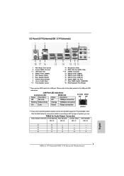
... Connector USB 2.0 Ports (USB01) USB 3.0 Ports (USB_23) USB 3.0 Ports (USB_01) Optical SPDIF Out Port Clear CMOS Switch (CLRCBTN) PS/2 Keyboard Port (Purple) * There are two LED next to the table below for connection details in accordance with the type of speaker you use . LAN Port LED Indications Activity/Link LED SPEED LED Status Description Status Description ACT/LINK SPEED LED LED Off No Link Off 10Mbps connection Blinking Data Activity Orange 100Mbps connection On Link Green 1Gbps connection LAN Port ** If you use 2-channel speaker, please connect...
... Connector USB 2.0 Ports (USB01) USB 3.0 Ports (USB_23) USB 3.0 Ports (USB_01) Optical SPDIF Out Port Clear CMOS Switch (CLRCBTN) PS/2 Keyboard Port (Purple) * There are two LED next to the table below for connection details in accordance with the type of speaker you use . LAN Port LED Indications Activity/Link LED SPEED LED Status Description Status Description ACT/LINK SPEED LED LED Off No Link Off 10Mbps connection Blinking Data Activity Orange 100Mbps connection On Link Green 1Gbps connection LAN Port ** If you use 2-channel speaker, please connect...
Quick Installation Guide
Page 8
... to change without further notice. You may find the latest VGA cards and CPU support lists on ASRock website without notice. To get better performance in Windows® 7 / 7 64-bit / VistaTM / VistaTM 64bit, it is recommended to AHCI mode. For the BIOS setup, please refer to the "User Manual" in Storage Configuration to set the BIOS option in our support CD for purchasing ASRock X79 Extreme6/GB / X79 Extreme6 motherboard, a reliable motherboard produced under ASRock...
... to change without further notice. You may find the latest VGA cards and CPU support lists on ASRock website without notice. To get better performance in Windows® 7 / 7 64-bit / VistaTM / VistaTM 64bit, it is recommended to AHCI mode. For the BIOS setup, please refer to the "User Manual" in Storage Configuration to set the BIOS option in our support CD for purchasing ASRock X79 Extreme6/GB / X79 Extreme6 motherboard, a reliable motherboard produced under ASRock...
Quick Installation Guide
Page 11
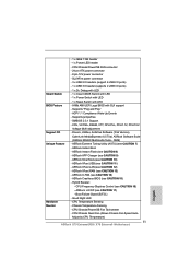
...CPU/Chassis/Power/SB Fan Tachometer - CPU/Chassis Quiet Fan (Allows Chassis Fan Speed Auto- ACPI 1.1 Compliance Wake Up Events - SLI/XFire power connector - 3 x USB 2.0 headers (support 6 USB 2.0 ports) - 1 x USB 3.0 header (supports 2 USB 3.0 ports) - 1 x Dr. Debug with LED Smart Switch - 1 x Clear CMOS Switch with LED - 1 x Power Switch with LED - 1 x Reset Switch with LED BIOS Feature - 64Mb AMI UEFI Legal BIOS with GUI support - OEM) Unique Feature - Chassis Temperature Sensing - Adjust by CPU Temperature) 11 ASRock X79 Extreme6/GB / X79 Extreme6 Motherboard...
...CPU/Chassis/Power/SB Fan Tachometer - CPU/Chassis Quiet Fan (Allows Chassis Fan Speed Auto- ACPI 1.1 Compliance Wake Up Events - SLI/XFire power connector - 3 x USB 2.0 headers (support 6 USB 2.0 ports) - 1 x USB 3.0 header (supports 2 USB 3.0 ports) - 1 x Dr. Debug with LED Smart Switch - 1 x Clear CMOS Switch with LED - 1 x Power Switch with LED - 1 x Reset Switch with LED BIOS Feature - 64Mb AMI UEFI Legal BIOS with GUI support - OEM) Unique Feature - Chassis Temperature Sensing - Adjust by CPU Temperature) 11 ASRock X79 Extreme6/GB / X79 Extreme6 Motherboard...
Quick Installation Guide
Page 13
... utility embedded in a user-friendly interface, which includes Hardware Monitor, Fan Control, Overclocking, OC DNA and IES. Your friends then can boost USB storage device performance. ASRock website: http://www.asrock.com/Feature/SmartView/index.asp 11. In OC DNA, you can update your real-time newsfeed into the BIOS setup menu to enter into an enhanced view for the operation procedures of the device. 13 ASRock X79 Extreme6/GB / X79 Extreme6 Motherboard...
... utility embedded in a user-friendly interface, which includes Hardware Monitor, Fan Control, Overclocking, OC DNA and IES. Your friends then can boost USB storage device performance. ASRock website: http://www.asrock.com/Feature/SmartView/index.asp 11. In OC DNA, you can update your real-time newsfeed into the BIOS setup menu to enter into an enhanced view for the operation procedures of the device. 13 ASRock X79 Extreme6/GB / X79 Extreme6 Motherboard...
Quick Installation Guide
Page 42
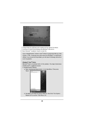
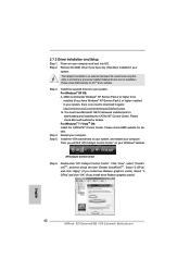
... then check the item "Enable CrossFireXTM". Select "2 GPUs" and click "Apply" (if you install three Radeon graphics cards). English 42 ASRock X79 Extreme6/GB / X79 Extreme6 Motherboard Install the required drivers to installation. For Windows® XP OS: A. Install the VGA card drivers to uninstall any VGA driver installed in your Windows® taskbar. Double-click "ATI Catalyst Control Center". Power on your system, there is an optional download. We recommend using this utility to your system, and...
... then check the item "Enable CrossFireXTM". Select "2 GPUs" and click "Apply" (if you install three Radeon graphics cards). English 42 ASRock X79 Extreme6/GB / X79 Extreme6 Motherboard Install the required drivers to installation. For Windows® XP OS: A. Install the VGA card drivers to uninstall any VGA driver installed in your Windows® taskbar. Double-click "ATI Catalyst Control Center". Power on your system, there is an optional download. We recommend using this utility to your system, and...
Quick Installation Guide
Page 54
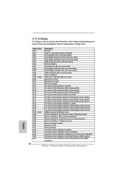
... Memory Installed CPU post-memory initialization is used Power on. Boot Strap Processor (BSP) selection CPU post-memory initialization. 2.13 Dr. Debug Dr. Debug is started Pre-memory South Bridge initialization (South Bridge module specific) Pre-memory South Bridge initialization (South Bridge module specific) Pre-memory South Bridge initialization (South Bridge module specific) OEM pre-memory initialization codes Memory initialization. Serial Presence Detect (SPD) data reading Memory initialization. Memory...
... Memory Installed CPU post-memory initialization is used Power on. Boot Strap Processor (BSP) selection CPU post-memory initialization. 2.13 Dr. Debug Dr. Debug is started Pre-memory South Bridge initialization (South Bridge module specific) Pre-memory South Bridge initialization (South Bridge module specific) Pre-memory South Bridge initialization (South Bridge module specific) OEM pre-memory initialization codes Memory initialization. Serial Presence Detect (SPD) data reading Memory initialization. Memory...
Quick Installation Guide
Page 58
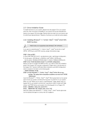
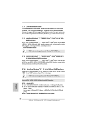
... the Support CD for detailed procedures: ..\ RAID Installation Guide RAID mode is not supported under Windows® XP / XP 64-bit. Enter UEFI SETUP UTILITY Advanced screen Storage Configuration. Then, the drivers compatible to your system can work properly. 2.15 Installing Windows® 7 / 7 64-bit / VistaTM / VistaTM 64-bit With RAID Functions If you want to install Windows® 7 / 7 64-bit / VistaTM / VistaTM 64-bit / XP / XP 64bit OS on your system. 58 ASRock X79 Extreme6/GB / X79 Extreme6 Motherboard English...
... the Support CD for detailed procedures: ..\ RAID Installation Guide RAID mode is not supported under Windows® XP / XP 64-bit. Enter UEFI SETUP UTILITY Advanced screen Storage Configuration. Then, the drivers compatible to your system can work properly. 2.15 Installing Windows® 7 / 7 64-bit / VistaTM / VistaTM 64-bit With RAID Functions If you want to install Windows® 7 / 7 64-bit / VistaTM / VistaTM 64-bit / XP / XP 64bit OS on your system. 58 ASRock X79 Extreme6/GB / X79 Extreme6 Motherboard English...
Quick Installation Guide
Page 65
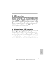
... BIOS Setup program is designed to the User Manual (PDF file) contained in your CD-ROM drive. Software Support CD information This motherboard supports various Microsoft® Windows® operating systems: 7 / 7 64-bit / VistaTM / VistaTM 64-bit / XP / XP 64-bit. The Support CD that will display the Main Menu automatically if "AUTORUN" is a menu-driven program, which allows you start up the computer, please press or during the Power-On...
... BIOS Setup program is designed to the User Manual (PDF file) contained in your CD-ROM drive. Software Support CD information This motherboard supports various Microsoft® Windows® operating systems: 7 / 7 64-bit / VistaTM / VistaTM 64-bit / XP / XP 64-bit. The Support CD that will display the Main Menu automatically if "AUTORUN" is a menu-driven program, which allows you start up the computer, please press or during the Power-On...
RAID Installation Guide
Page 6
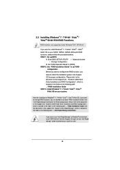
... the document in the Support CD, "Guide to SATA Hard Disks Installation and RAID Configuration", which is located in Windows® environment, install "SATA2 driver" from the Support CD again so that "Intel Rapid Storage" will be installed to your system. 2.3 Installing Windows® 7 / 7 64-bit / VistaTM / VistaTM 64-bit With RAID Functions RAID mode is located in the Support CD for RAID configuration. STEP 2: Use "RAID Installation Guide" to [RAID]. Enter BIOS SETUP UTILITY Advanced screen Storage Configuration...
... the document in the Support CD, "Guide to SATA Hard Disks Installation and RAID Configuration", which is located in Windows® environment, install "SATA2 driver" from the Support CD again so that "Intel Rapid Storage" will be installed to your system. 2.3 Installing Windows® 7 / 7 64-bit / VistaTM / VistaTM 64-bit With RAID Functions RAID mode is located in the Support CD for RAID configuration. STEP 2: Use "RAID Installation Guide" to [RAID]. Enter BIOS SETUP UTILITY Advanced screen Storage Configuration...

Intel Rapid Storage Guide
Page 13
... S to confirm volume creation. 10. Use the up and down arrow keys to create a floppy disk with a screen asking you have successfully installed the driver and Windows setup should continue. At this point, you to install a third party SCSI or RAID driver. Press F6 when you need to load support for mass storage device(s). 2. Press Enter to install the Intel Rapid Storage Technology driver during text-mode phase). When you see a prompt...
... S to confirm volume creation. 10. Use the up and down arrow keys to create a floppy disk with a screen asking you have successfully installed the driver and Windows setup should continue. At this point, you to install a third party SCSI or RAID driver. Press F6 when you need to load support for mass storage device(s). 2. Press Enter to install the Intel Rapid Storage Technology driver during text-mode phase). When you see a prompt...


