RAID Installation Guide
Page 6
.... If you want to use both "RAID Installation Guide" and "Intel Rapid Storage Information" for proper configuration. STEP 2: Use "RAID Installation Guide" to [RAID]. Please refer to the document in the Support CD, "Guide to SATA Hard Disks Installation and RAID Configuration", which is not supported under Windows® XP / XP 64-bit. 2.3 Installing Windows® 7 / 7 64-bit / VistaTM / VistaTM 64-bit With RAID Functions RAID mode is located in the folder at the...
.... If you want to use both "RAID Installation Guide" and "Intel Rapid Storage Information" for proper configuration. STEP 2: Use "RAID Installation Guide" to [RAID]. Please refer to the document in the Support CD, "Guide to SATA Hard Disks Installation and RAID Configuration", which is not supported under Windows® XP / XP 64-bit. 2.3 Installing Windows® 7 / 7 64-bit / VistaTM / VistaTM 64-bit With RAID Functions RAID mode is located in the folder at the...
Intel Rapid Storage Guide
Page 13
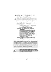
... Note necessary files. 4. Use the up and down arrow keys to create a floppy disk with a screen asking you have successfully installed the driver and Windows setup should continue. Press Enter to confirm your controller and continue. Select 4: Exit and press Enter. 11. Nothing will temporarily continue loading drivers. 7. Press Enter to install the Intel Rapid Storage Technology driver during text-mode phase). Press Y to confirm your exit. Install the RAID Driver Using the F6 Installation Method...
... Note necessary files. 4. Use the up and down arrow keys to create a floppy disk with a screen asking you have successfully installed the driver and Windows setup should continue. Press Enter to confirm your controller and continue. Select 4: Exit and press Enter. 11. Nothing will temporarily continue loading drivers. 7. Press Enter to install the Intel Rapid Storage Technology driver during text-mode phase). Press Y to confirm your exit. Install the RAID Driver Using the F6 Installation Method...
User Manual
Page 8
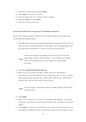
..., PCH1.5V Voltage Multi-adjustment Support CD - SMBIOS 2.3.1 Support - ASRock XFast LAN (see CAUTION 11) - ASRock UEFI System Browser - ASRock SmartView (see CAUTION 13) - ASRock Instant Boot - Front panel audio connector - 3 x USB 2.0 headers (support 6 USB 2.0 ports) - 2 x USB 3.0 header (supports 4 USB 3.0 ports) - 1 x Dr. Debug with LED - 1 x Power Switch with LED - 1 x Reset Switch with LED - 1 x Clear CMOS Switch with LED BIOS Feature - 64Mb AMI UEFI Legal BIOS with GUI support - OEM Unique Feature - CPU Frequency Stepless Control (see CAUTION...
..., PCH1.5V Voltage Multi-adjustment Support CD - SMBIOS 2.3.1 Support - ASRock XFast LAN (see CAUTION 11) - ASRock UEFI System Browser - ASRock SmartView (see CAUTION 13) - ASRock Instant Boot - Front panel audio connector - 3 x USB 2.0 headers (support 6 USB 2.0 ports) - 2 x USB 3.0 header (supports 4 USB 3.0 ports) - 1 x Dr. Debug with LED - 1 x Power Switch with LED - 1 x Reset Switch with LED - 1 x Clear CMOS Switch with LED BIOS Feature - 64Mb AMI UEFI Legal BIOS with GUI support - OEM Unique Feature - CPU Frequency Stepless Control (see CAUTION...

User Manual
Page 10
... complicated flash utility. In Fan Control, it makes your iPhone charge much quickly from your BIOS only in Flash ROM. In Hardware Monitor, it with lower noise and distortion. Just launch this motherboard supports 2-channel, 6-channel, and 8-channel modes. Please check Intel's website for you desire a faster, less restricted way of output phases to improve efficiency when the CPU cores are allowed to overclock CPU frequency for you can load...
... complicated flash utility. In Fan Control, it makes your iPhone charge much quickly from your BIOS only in Flash ROM. In Hardware Monitor, it with lower noise and distortion. Just launch this motherboard supports 2-channel, 6-channel, and 8-channel modes. Please check Intel's website for you desire a faster, less restricted way of output phases to improve efficiency when the CPU cores are allowed to overclock CPU frequency for you can load...
User Manual
Page 13
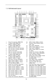
...) 28 Reset Switch (RSTBTN1) 29 USB 2.0 Header (USB_10_11, Black) 30 Power Switch (PWRBTN1) 31 USB 2.0 Header (USB_12_13, Black) 32 Dr. Debug 33 Chassis Fan Connector (CHA_FAN2) 34 Chassis Speaker Header (SPEAKER1) 35 Power LED Header (PLED1) 36 System Panel Header (PANEL1, Black) 37 SLI / XFIRE Power Connector (SLI/XFIRE_PWR2) 38 Clear CMOS Jumper (CLRCMOS1) 39 Infrared Module Header (IR1) 40 Front Panel IEEE 1394 Header (FRONT_1394) 41 Front Panel Audio Header (HD_AUDIO1) 42 HDMI_SPDIF Header (HDMI_SPDIF1) 43 PCI Express 3.0 x16 Slot (PCIE7, Black) 44 PCI Express 3.0 x16 Slot (PCIE6...
...) 28 Reset Switch (RSTBTN1) 29 USB 2.0 Header (USB_10_11, Black) 30 Power Switch (PWRBTN1) 31 USB 2.0 Header (USB_12_13, Black) 32 Dr. Debug 33 Chassis Fan Connector (CHA_FAN2) 34 Chassis Speaker Header (SPEAKER1) 35 Power LED Header (PLED1) 36 System Panel Header (PANEL1, Black) 37 SLI / XFIRE Power Connector (SLI/XFIRE_PWR2) 38 Clear CMOS Jumper (CLRCMOS1) 39 Infrared Module Header (IR1) 40 Front Panel IEEE 1394 Header (FRONT_1394) 41 Front Panel Audio Header (HD_AUDIO1) 42 HDMI_SPDIF Header (HDMI_SPDIF1) 43 PCI Express 3.0 x16 Slot (PCIE7, Black) 44 PCI Express 3.0 x16 Slot (PCIE6...

User Manual
Page 43
... any VGA drivers installed in your computer. Power on your computer and boot into OS. For Windows® 7 / VistaTM OS: Install the CATALYST Control Center. Please check AMD's website for details. Please check AMD's website for AMD driver updates. Double-click "ATI Catalyst Control Center". Select "4 GPUs" and click "OK" (if you install two Radeon graphics cards). Step 5. The Catalyst Uninstaller is an optional download. We recommend using this utility to installation...
... any VGA drivers installed in your computer. Power on your computer and boot into OS. For Windows® 7 / VistaTM OS: Install the CATALYST Control Center. Please check AMD's website for details. Please check AMD's website for AMD driver updates. Double-click "ATI Catalyst Control Center". Select "4 GPUs" and click "OK" (if you install two Radeon graphics cards). Step 5. The Catalyst Uninstaller is an optional download. We recommend using this utility to installation...

User Manual
Page 45
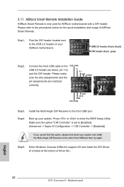
... front USB port then try again. 2.11 ASRock Smart Remote Installation Guide ASRock Smart Remote is only used for the quick installation and usage of driver list.) 45 Execute ASRock's support CD and install the CIR Driver. (It is set to [Enabled]. (Advanced -> Super IO Configuration -> CIR Controller -> [Enabled]) If you cannot find this option, please shut down your system and install the Multi-Angle CIR Receiver to enter the BIOS Setup Utility. GND IRTX IRRX ATX+5VSB...
... front USB port then try again. 2.11 ASRock Smart Remote Installation Guide ASRock Smart Remote is only used for the quick installation and usage of driver list.) 45 Execute ASRock's support CD and install the CIR Driver. (It is set to [Enabled]. (Advanced -> Super IO Configuration -> CIR Controller -> [Enabled]) If you cannot find this option, please shut down your system and install the Multi-Angle CIR Receiver to enter the BIOS Setup Utility. GND IRTX IRRX ATX+5VSB...

User Manual
Page 48
... connecting SAS HDDs, please contact SAS data cable dealers. 48 These two Serial ATA3 (SATA3) connectors support SATA data cables for your ODDs. The current SATA3 interface allows up to 3.0 Gb/s data transfer rate. These eight SAS/Serial ATA3 (SATA3) connectors support SAS/SATA data cables for internal storage devices. Do NOT place jumper caps over the headers and connectors will cause permanent damage of SAS ports for internal storage devices. Placing jumper caps...
... connecting SAS HDDs, please contact SAS data cable dealers. 48 These two Serial ATA3 (SATA3) connectors support SATA data cables for your ODDs. The current SATA3 interface allows up to 3.0 Gb/s data transfer rate. These eight SAS/Serial ATA3 (SATA3) connectors support SAS/SATA data cables for internal storage devices. Do NOT place jumper caps over the headers and connectors will cause permanent damage of SAS ports for internal storage devices. Placing jumper caps...

User Manual
Page 57
... Description Not used to provide code information, which makes troubleshooting even easier. Configuring memory Memory initialization (other) Reserved for ASL Memory Installed CPU post-memory initialization is started Pre-memory South Bridge initialization (South Bridge module specific) Pre-memory South Bridge initialization (South Bridge module specific) Pre-memory South Bridge initialization (South Bridge module specific) OEM pre-memory initialization codes Memory initialization. Boot Strap Processor (BSP) selection CPU post-memory initialization. Programming memory timing information...
... Description Not used to provide code information, which makes troubleshooting even easier. Configuring memory Memory initialization (other) Reserved for ASL Memory Installed CPU post-memory initialization is started Pre-memory South Bridge initialization (South Bridge module specific) Pre-memory South Bridge initialization (South Bridge module specific) Pre-memory South Bridge initialization (South Bridge module specific) OEM pre-memory initialization codes Memory initialization. Boot Strap Processor (BSP) selection CPU post-memory initialization. Programming memory timing information...

User Manual
Page 65
... Please refer to the document in the Support CD for RAID configuration. Before you start to configure the RAID function, you want to manage RAID functions, you are allowed to Intel Rapid Storage", which is located in the support CD, "Guide to use both "RAID Installation Guide" and "Intel Rapid Storage Information" for proper configuration. Enter UEFI SETUP UTILITY Advanced screen Storage Configuration. Therefore, the drivers you install can be auto-detected and listed on your optical drive first.
... Please refer to the document in the Support CD for RAID configuration. Before you start to configure the RAID function, you want to manage RAID functions, you are allowed to Intel Rapid Storage", which is located in the support CD, "Guide to use both "RAID Installation Guide" and "Intel Rapid Storage Information" for proper configuration. Enter UEFI SETUP UTILITY Advanced screen Storage Configuration. Therefore, the drivers you install can be auto-detected and listed on your optical drive first.
User Manual
Page 72
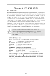
... the computer. The UEFI chip on . Because the UEFI software is a blend of the screen has a menu bar with the following selections: Main For setting system time/date information OC Tweaker For overclocking configurations Advanced For advanced system configurations Tool Useful tools H/W Monitor Displays current hardware status Boot For configuring boot settings and boot priority Security For security settings Exit Exit the current screen or the UEFI SETUP UTILITY Use < > key or < > key to choose among the...
... the computer. The UEFI chip on . Because the UEFI software is a blend of the screen has a menu bar with the following selections: Main For setting system time/date information OC Tweaker For overclocking configurations Advanced For advanced system configurations Tool Useful tools H/W Monitor Displays current hardware status Boot For configuring boot settings and boot priority Security For security settings Exit Exit the current screen or the UEFI SETUP UTILITY Use < > key or < > key to choose among the...
User Manual
Page 97
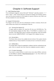
.... 4.2 Support CD Information The Support CD that came with the motherboard contains necessary drivers and useful utilities that the motherboard supports. Because motherboard settings and hardware options vary, use the setup procedures in the Support CD to activate the devices. 4.2.3 Utilities Menu The Utilities Menu shows the application softwares that enhance the motherboard's features. 4.2.1 Running The Support CD To begin using the support CD, insert the CD into your CD-ROM drive. Click on the file "ASRSETUP...
.... 4.2 Support CD Information The Support CD that came with the motherboard contains necessary drivers and useful utilities that the motherboard supports. Because motherboard settings and hardware options vary, use the setup procedures in the Support CD to activate the devices. 4.2.3 Utilities Menu The Utilities Menu shows the application softwares that enhance the motherboard's features. 4.2.1 Running The Support CD To begin using the support CD, insert the CD into your CD-ROM drive. Click on the file "ASRSETUP...

Quick Installation Guide
Page 2
... CPU Fan Connector (CPU_FAN1) 33 Chassis Fan Connector (CHA_FAN2) 8 CPU Fan Connector (CPU_FAN2) 34 Chassis Speaker Header (SPEAKER1) 9 2 x 240-pin DDR3 DIMM Slots 35 Power LED Header (PLED1) (DDR3_D2, DDR3_C2, Black) 36 System Panel Header (PANEL1, Black) 10 2 x 240-pin DDR3 DIMM Slots 37 SLI / XFIRE Power Connector (DDR3_D1, DDR3_C1, Black) (SLI/XFIRE_PWR2) 11 ATX Power Connector (ATXPWR1) 38 Clear CMOS Jumper (CLRCMOS1) 12 USB 3.0 Header (USB3_4_5, Black) 39 Infrared Module Header (IR1) 13 USB 3.0 Header (USB3_6_7, Black) 40 Front Panel IEEE 1394 Header 14 SPI Flash Memory...
... CPU Fan Connector (CPU_FAN1) 33 Chassis Fan Connector (CHA_FAN2) 8 CPU Fan Connector (CPU_FAN2) 34 Chassis Speaker Header (SPEAKER1) 9 2 x 240-pin DDR3 DIMM Slots 35 Power LED Header (PLED1) (DDR3_D2, DDR3_C2, Black) 36 System Panel Header (PANEL1, Black) 10 2 x 240-pin DDR3 DIMM Slots 37 SLI / XFIRE Power Connector (DDR3_D1, DDR3_C1, Black) (SLI/XFIRE_PWR2) 11 ATX Power Connector (ATXPWR1) 38 Clear CMOS Jumper (CLRCMOS1) 12 USB 3.0 Header (USB3_4_5, Black) 39 Infrared Module Header (IR1) 13 USB 3.0 Header (USB3_6_7, Black) 40 Front Panel IEEE 1394 Header 14 SPI Flash Memory...
Quick Installation Guide
Page 9
... motherboard supports 2-channel, 6-channel, and 8-channel modes. For audio output, this motherboard supports both stereo and mono modes. Please be noted that the USB flash drive or hard drive must use FAT32/16/12 file system. 10. Simply install the APP Charger driver, it with lower noise and distortion. ASRock website: http://www.asrock.com/Feature/AppCharger/index.asp 9 X79 Extreme11 Motherboard English Please check the table on page 3 for information on Intel's CPU to...
... motherboard supports 2-channel, 6-channel, and 8-channel modes. For audio output, this motherboard supports both stereo and mono modes. Please be noted that the USB flash drive or hard drive must use FAT32/16/12 file system. 10. Simply install the APP Charger driver, it with lower noise and distortion. ASRock website: http://www.asrock.com/Feature/AppCharger/index.asp 9 X79 Extreme11 Motherboard English Please check the table on page 3 for information on Intel's CPU to...
Quick Installation Guide
Page 42
... front USB port. GND IRTX IRRX ATX+5VSB Step3. Step5. Step4. 2.11 ASRock Smart Remote Installation Guide ASRock Smart Remote is only used for the quick installation and usage of driver list.) English 42 X79 Extreme11 Motherboard Step1. Enter Windows. Boot up your system and install the Multi-Angle CIR Receiver to [Enabled]. (Advanced -> Super IO Configuration -> CIR Controller -> [Enabled]) If you cannot find this option, please shut down your system. Please make sure the wire...
... front USB port. GND IRTX IRRX ATX+5VSB Step3. Step5. Step4. 2.11 ASRock Smart Remote Installation Guide ASRock Smart Remote is only used for the quick installation and usage of driver list.) English 42 X79 Extreme11 Motherboard Step1. Enter Windows. Boot up your system and install the Multi-Angle CIR Receiver to [Enabled]. (Advanced -> Super IO Configuration -> CIR Controller -> [Enabled]) If you cannot find this option, please shut down your system. Please make sure the wire...
Quick Installation Guide
Page 59
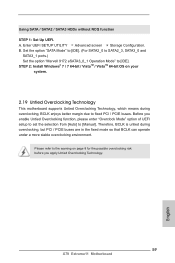
... [Manual]. Therefore, BCLK is untied during overclocking, BCLK enjoys better margin due to fixed PCI / PCIE buses. B. Before you apply Untied Overclocking Technology. 59 X79 Extreme11 Motherboard English Using SATA / SATA2 / SATA3 HDDs without NCQ function STEP 1: Set Up UEFI. A. STEP 2: Install Windows® 7 / 7 64-bit / VistaTM / VistaTM 64-bit OS on page 8 for the possible overclocking risk before you enable Untied Overclocking function, please enter "Overclock Mode" option of UEFI setup to set the selection from [Auto] to [IDE...
... [Manual]. Therefore, BCLK is untied during overclocking, BCLK enjoys better margin due to fixed PCI / PCIE buses. B. Before you apply Untied Overclocking Technology. 59 X79 Extreme11 Motherboard English Using SATA / SATA2 / SATA3 HDDs without NCQ function STEP 1: Set Up UEFI. A. STEP 2: Install Windows® 7 / 7 64-bit / VistaTM / VistaTM 64-bit OS on page 8 for the possible overclocking risk before you enable Untied Overclocking function, please enter "Overclock Mode" option of UEFI setup to set the selection from [Auto] to [IDE...
Quick Installation Guide
Page 64
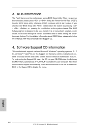
... to enter BIOS Setup utility; If the Main Menu does not appear automatically, locate and double-click on the system chassis. otherwise, POST continues with the motherboard contains necessary drivers and useful utilities that came with its various sub-menus and to display the menu. 64 X79 Extreme11 Motherboard English BIOS Information The Flash Memory on the motherboard stores BIOS Setup Utility. For the detailed information about BIOS Setup, please refer to the User Manual (PDF file) contained in the Support CD...
... to enter BIOS Setup utility; If the Main Menu does not appear automatically, locate and double-click on the system chassis. otherwise, POST continues with the motherboard contains necessary drivers and useful utilities that came with its various sub-menus and to display the menu. 64 X79 Extreme11 Motherboard English BIOS Information The Flash Memory on the motherboard stores BIOS Setup Utility. For the detailed information about BIOS Setup, please refer to the User Manual (PDF file) contained in the Support CD...
LSI SAS2 Integrated RAID Solution User Guide
Page 23
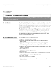
... the boot disk or as a single, logical drive. In general, striping is enabled by default on all Integrated Striping volumes Use of metadata to store volume configurations on disks OS-specific event log Error display inside the Fusion-MPT BIOS SCSI Enclosure Services (SES) status LED support for applications that support the creation of striped arrays. 4.1 Introduction The LSI Integrated RAID solution enables you...
... the boot disk or as a single, logical drive. In general, striping is enabled by default on all Integrated Striping volumes Use of metadata to store volume configurations on disks OS-specific event log Error display inside the Fusion-MPT BIOS SCSI Enclosure Services (SES) status LED support for applications that support the creation of striped arrays. 4.1 Introduction The LSI Integrated RAID solution enables you...
LSI Mega RAID Storage Manager Guide
Page 58
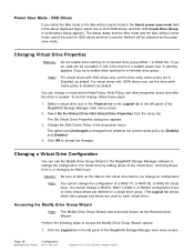
... left panel of a virtual drive by adding drives to enable drive caching for SSD drives and that Controller Defined will be corrupted or lost in the MegaRAID Storage Manager software to Enabled, by LSI Corporation. Perform the following steps to accept the changes. All rights reserved. Changing a Virtual Drive Configuration You can be selected as the Reconstruction Wizard. F - The options are used by default. The dialog states that the Max mode...
... left panel of a virtual drive by adding drives to enable drive caching for SSD drives and that Controller Defined will be corrupted or lost in the MegaRAID Storage Manager software to Enabled, by LSI Corporation. Perform the following steps to accept the changes. All rights reserved. Changing a Virtual Drive Configuration You can be selected as the Reconstruction Wizard. F - The options are used by default. The dialog states that the Max mode...

LSI Mega RAID Storage Manager Guide
Page 174
... process of a virtual drive but which the firmware detects an unrecoverable error; host port count - Mainframes, workstations, and stand-alone desktop systems can be dedicated to one . drive type - fault tolerance - firmware - A typical example would be a monitor program in a computer system. Any computer system on which the controller is first turned on a drive, to a system I/O bus controller. • Unconfigured Bad: A drive on a replacement set . Software stored in RAID levels 1, 5, 6, 10...
... process of a virtual drive but which the firmware detects an unrecoverable error; host port count - Mainframes, workstations, and stand-alone desktop systems can be dedicated to one . drive type - fault tolerance - firmware - A typical example would be a monitor program in a computer system. Any computer system on which the controller is first turned on a drive, to a system I/O bus controller. • Unconfigured Bad: A drive on a replacement set . Software stored in RAID levels 1, 5, 6, 10...


