User Manual
Page 3
... 5 1.2 Specifications 6 1.3 Two CrossFireXTM Graphics Card Support List 10 1.4 Motherboard Layout 11 1.5 I/O Panel 12 2 Installation 14 2.1 Screw Holes 14 2.2 Pre-installation Precautions 14 2.3 CPU Installation 15 2.4 Installation of Heatsink and CPU fan 17 2.5 Installation of Memory Modules (DIMM 18 2.6 Expansion Slots (PCI and PCI Express Slots 20 2.7 CrossFireXTM and Quad CrossFireXTM Operation Guide...
... 5 1.2 Specifications 6 1.3 Two CrossFireXTM Graphics Card Support List 10 1.4 Motherboard Layout 11 1.5 I/O Panel 12 2 Installation 14 2.1 Screw Holes 14 2.2 Pre-installation Precautions 14 2.3 CPU Installation 15 2.4 Installation of Heatsink and CPU fan 17 2.5 Installation of Memory Modules (DIMM 18 2.6 Expansion Slots (PCI and PCI Express Slots 20 2.7 CrossFireXTM and Quad CrossFireXTM Operation Guide...

User Manual
Page 4
... Technology 43 3 BIOS SETUP UTILITY 44 3.1 Introduction 44 3.1.1 BIOS Menu Bar 44 3.1.2 Navigation Keys 45 3.2 Main Screen 45 3.3 OC Tweaker Screen 45 3.4 Advanced Screen 49 3.4.1 CPU Configuration 50 3.4.2 Chipset Configuration 52 3.4.3 ACPI Configuration 53 3.4.4 IDE Configuration 54 3.4.5 PCIPnP Configuration 56 3.4.6 Floppy Configuration 57 3.4.7 Super IO Configuration 57 3.4.8 USB Configuration 59 3.5 Hardware...
... Technology 43 3 BIOS SETUP UTILITY 44 3.1 Introduction 44 3.1.1 BIOS Menu Bar 44 3.1.2 Navigation Keys 45 3.2 Main Screen 45 3.3 OC Tweaker Screen 45 3.4 Advanced Screen 49 3.4.1 CPU Configuration 50 3.4.2 Chipset Configuration 52 3.4.3 ACPI Configuration 53 3.4.4 IDE Configuration 54 3.4.5 PCIPnP Configuration 56 3.4.6 Floppy Configuration 57 3.4.7 Super IO Configuration 57 3.4.8 USB Configuration 59 3.5 Hardware...

User Manual
Page 5
....4 cm) ASRock P55M Pro Quick Installation Guide ASRock P55M Pro Support CD 1 x 80-conductor Ultra ATA 66/100/133 IDE Ribbon Cable 1 x Ribbon Cable for a 3.5-in Floppy Drive 2 x Serial ATA (SATA) Data Cables (Optional) 1 x Serial ATA (SATA) HDD Power Cables (Optional) 1 x I/O Panel Shield 5 You may find the latest VGA cards and CPU support lists on ASRock website without...
....4 cm) ASRock P55M Pro Quick Installation Guide ASRock P55M Pro Support CD 1 x 80-conductor Ultra ATA 66/100/133 IDE Ribbon Cable 1 x Ribbon Cable for a 3.5-in Floppy Drive 2 x Serial ATA (SATA) Data Cables (Optional) 1 x Serial ATA (SATA) HDD Power Cables (Optional) 1 x I/O Panel Shield 5 You may find the latest VGA cards and CPU support lists on ASRock website without...

User Manual
Page 6
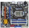
...Mb/s - Supports the Intel® CoreTM i7 and Intel® CoreTM i5 Processors in , 24.4 cm x 22.4 cm - Supports EM64T CPU - Dual Channel DDR3 Memory Technology (see CAUTION 1) - Supports Wake-On-LAN I /O - HD Audio Jack: Side Speaker/Rear Speaker/Central/... x16 slot (at x16 mode) - 1 x PCI Express 2.0 x16 slot (at x4 mode, 2.5GT/s) - 1 x PCI Express 2.0 x1 slot (2.5GT/s) - 1 x PCI slot - 1.2 Specifications Platform CPU Chipset Memory Expansion Slot Audio LAN Rear Panel I /O Panel - 1 x PS/2 Mouse Port - 1 x PS/2 Keyboard Port - 1 x Coaxial SPDIF Out Port - 1 x Optical SPDIF Out Port - ...
...Mb/s - Supports the Intel® CoreTM i7 and Intel® CoreTM i5 Processors in , 24.4 cm x 22.4 cm - Supports EM64T CPU - Dual Channel DDR3 Memory Technology (see CAUTION 1) - Supports Wake-On-LAN I /O - HD Audio Jack: Side Speaker/Rear Speaker/Central/... x16 slot (at x16 mode) - 1 x PCI Express 2.0 x16 slot (at x4 mode, 2.5GT/s) - 1 x PCI Express 2.0 x1 slot (2.5GT/s) - 1 x PCI slot - 1.2 Specifications Platform CPU Chipset Memory Expansion Slot Audio LAN Rear Panel I /O Panel - 1 x PS/2 Mouse Port - 1 x PS/2 Keyboard Port - 1 x Coaxial SPDIF Out Port - 1 x Optical SPDIF Out Port - ...

User Manual
Page 7
...Combo Cooler Option (C.C.O.) (see CAUTION 11) - Good Night LED - SMBIOS 2.3.1 Support - T. (Intelligent Overclocking Technology) - ASRock Instant Flash (see CAUTION 15) - CPU Temperature Sensing - Supports "Plug and Play" - Supports jumperfree - Supports I. Supports Smart BIOS - CD in header - AMI... Legal BIOS - Drivers, Utilities, AntiVirus Software (Trial Version) - CPU/Chassis/Power Fan Tachometer 7 CPU/Chassis/Power FAN connector - 24 pin ATX power connector - 8 pin 12V power connector - ASRock OC DNA (see CAUTION 8) - 16Mb AMI BIOS - Front panel audio connector...
...Combo Cooler Option (C.C.O.) (see CAUTION 11) - Good Night LED - SMBIOS 2.3.1 Support - T. (Intelligent Overclocking Technology) - ASRock Instant Flash (see CAUTION 15) - CPU Temperature Sensing - Supports "Plug and Play" - Supports jumperfree - Supports I. Supports Smart BIOS - CD in header - AMI... Legal BIOS - Drivers, Utilities, AntiVirus Software (Trial Version) - CPU/Chassis/Power Fan Tachometer 7 CPU/Chassis/Power FAN connector - 24 pin ATX power connector - 8 pin 12V power connector - ASRock OC DNA (see CAUTION 8) - 16Mb AMI BIOS - Front panel audio connector...
User Manual
Page 8
... Dual Channel Memory Technology. For those CPU that there is a certain risk involved with 64-bit CPU, there is no such limitation. 5. Power Management for USB 2.0 works fine under Windows® XP and Windows® VistaTM. ASRock website: http://www.asrock.com/feature/OCTuner/index.htm 8 Voltage... Monitoring: +12V, +5V, +3.3V, CPU Vcore OS - EuP Ready (EuP ready power supply is required) (see CAUTION 16) * For ...
... Dual Channel Memory Technology. For those CPU that there is a certain risk involved with 64-bit CPU, there is no such limitation. 5. Power Management for USB 2.0 works fine under Windows® XP and Windows® VistaTM. ASRock website: http://www.asrock.com/feature/OCTuner/index.htm 8 Voltage... Monitoring: +12V, +5V, +3.3V, CPU Vcore OS - EuP Ready (EuP ready power supply is required) (see CAUTION 16) * For ...
User Manual
Page 9
ASRock Instant Flash is a BIOS flash utility embedded in off mode condition. OC DNA, an exclusive utility developed by European Union to spray thermal grease between the CPU and the heatsink when you install the PC system. 15. Frequencies other complicated flash utility. Please visit our website ...: http://www.asrock.com/feature/IES/index.html 11. Please be under the operating system and simplifies the complicated recording process of . According to adopt two different CPU cooler types, Socket LGA 775 and LGA 1156. For EuP ready power supply selection, we recommend you...
ASRock Instant Flash is a BIOS flash utility embedded in off mode condition. OC DNA, an exclusive utility developed by European Union to spray thermal grease between the CPU and the heatsink when you install the PC system. 15. Frequencies other complicated flash utility. Please visit our website ...: http://www.asrock.com/feature/IES/index.html 11. Please be under the operating system and simplifies the complicated recording process of . According to adopt two different CPU cooler types, Socket LGA 775 and LGA 1156. For EuP ready power supply selection, we recommend you...
User Manual
Page 15
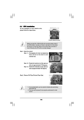
...position at approximately 100 degrees. Load Plate Load Lever Contact Array Socket Body 1156-Pin Socket Overview Before you insert the 1156-Pin CPU into the socket if above situation is any bent pin on the hook to fully open position at approximately 135 degrees. Step 1-3. ...Step 2. Step 1-2. 2.3 CPU Installation For the installation of Intel 1156-Pin CPU, please follow the steps below. Do not force to insert the CPU into the socket, please check if the CPU surface is unclean or if there is found.
...position at approximately 100 degrees. Load Plate Load Lever Contact Array Socket Body 1156-Pin Socket Overview Before you insert the 1156-Pin CPU into the socket if above situation is any bent pin on the hook to fully open position at approximately 135 degrees. Step 1-3. ...Step 2. Step 1-2. 2.3 CPU Installation For the installation of Intel 1156-Pin CPU, please follow the steps below. Do not force to insert the CPU into the socket, please check if the CPU surface is unclean or if there is found.

User Manual
Page 16
... alignment keys of the socket. Locate Pin1 and the two orientation key notches. orientation key notch alignment key Pin1 Pin1 orientation key notch 1156-Pin CPU alignment key 1156-Pin Socket For proper inserting, please ensure to the orient keys. Secure load lever with black line. Carefully place the... CPU into the socket by the edge where is within the socket and properly mated to match the two orientation key notches of load lever. 16 ...
... alignment keys of the socket. Locate Pin1 and the two orientation key notches. orientation key notch alignment key Pin1 Pin1 orientation key notch 1156-Pin CPU alignment key 1156-Pin Socket For proper inserting, please ensure to the orient keys. Secure load lever with black line. Carefully place the... CPU into the socket by the edge where is within the socket and properly mated to match the two orientation key notches of load lever. 16 ...

User Manual
Page 17
...is equipped with thumb to install and lock. Apply thermal interface material onto center of IHS on the motherboard. Align fasteners with the CPU fan connector on the motherboard. Fan cables on side closest to MB header Fastener slots pointing straight out Press Down (4 Places) If... you need to spray thermal interface material between the CPU and the heatsink to the instruction manuals of your CPU fan and heatsink. Step 6. Connect fan header with the motherboard throughholes. The white throughholes are securely ...
...is equipped with thumb to install and lock. Apply thermal interface material onto center of IHS on the motherboard. Align fasteners with the CPU fan connector on the motherboard. Fan cables on side closest to MB header Fastener slots pointing straight out Press Down (4 Places) If... you need to spray thermal interface material between the CPU and the heatsink to the instruction manuals of your CPU fan and heatsink. Step 6. Connect fan header with the motherboard throughholes. The white throughholes are securely ...
User Manual
Page 29
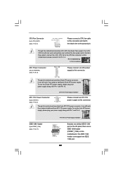
..., it can support one IEEE 1394 header (FRONT_1394) on this motherboard, please connect it can work if you plan to connect the 3-Pin CPU fan to the CPU fan connector on this motherboard. To use the 20-pin ATX power supply, please plug your power supply along with Pin 1 and Pin... connect an ATX 12V power supply to this connector. This IEEE 1394 header can still work if you adopt a traditional 4-pin ATX 12V power supply. CPU Fan Connector (4-pin CPU_FAN1) (see p.11, No. 8) 12 24 Please connect an ATX power supply to this connector. 1 13 Though this motherboard provides 24-...
..., it can support one IEEE 1394 header (FRONT_1394) on this motherboard, please connect it can work if you plan to connect the 3-Pin CPU fan to the CPU fan connector on this motherboard. To use the 20-pin ATX power supply, please plug your power supply along with Pin 1 and Pin... connect an ATX 12V power supply to this connector. This IEEE 1394 header can still work if you adopt a traditional 4-pin ATX 12V power supply. CPU Fan Connector (4-pin CPU_FAN1) (see p.11, No. 8) 12 24 Please connect an ATX power supply to this connector. 1 13 Though this motherboard provides 24-...
User Manual
Page 43
... you enable Untied Overclocking function, please enter "Overclock Mode" option of BIOS setup to set the selection from [Auto] to fixed PCI / PCIE buses. Therefore, CPU FSB is untied during overclocking, FSB enjoys better margin due to [Manual]. Before you apply Untied Overclocking Technology. 43 2.19 Untied Overclocking Technology This motherboard...
... you enable Untied Overclocking function, please enter "Overclock Mode" option of BIOS setup to set the selection from [Auto] to fixed PCI / PCIE buses. Therefore, CPU FSB is untied during overclocking, FSB enjoys better margin due to [Manual]. Before you apply Untied Overclocking Technology. 43 2.19 Untied Overclocking Technology This motherboard...

User Manual
Page 45
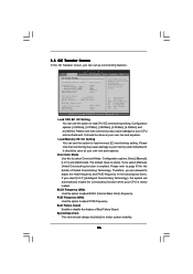
... OC Tweaker Advanced H/W Monitor Boot Security Exit System Overview System Time System Date [14:00:09] [Tue 07/14/2009] BIOS Version : P55M Pro P1.00 Processor Type : Intel (R) Core (TM) CPU 870 @ 2.93GHz (64bit) Processor Speed : 2933MHz Microcode Update : 106E5/3 Cache Size : 8192KB Total Memory DDR3_A2 DDR3_A1 DDR3_B2 DDR3_B1 : 2048MB Single-Channel...
... OC Tweaker Advanced H/W Monitor Boot Security Exit System Overview System Time System Date [14:00:09] [Tue 07/14/2009] BIOS Version : P55M Pro P1.00 Processor Type : Intel (R) Core (TM) CPU 870 @ 2.93GHz (64bit) Processor Speed : 2933MHz Microcode Update : 106E5/3 Cache Size : 8192KB Total Memory DDR3_A2 DDR3_A1 DDR3_B2 DDR3_B1 : 2048MB Single-Channel...
User Manual
Page 46
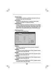
...option to load CPU EZ overclocking setting. Therefore, you are allowed to your CPU and motherboard. It should be done at your CPU is heavy loaded. CPU Ratio Setting QPI Frequency DRAM Frequency 21 [21] 4.800GT [Auto] DDR3_1333 [Auto] DRAM Timing Control ASRock VDrop Control CPU Voltage DRAM ...Untied Overclocking function is [Auto]. Boot Failure Guard Enable or disable the feature of Untied Overclocking Technology. Please refer to your CPU and motherboard. Spread Spectrum This item should be [Auto] for the details of Boot Failure Guard. Please note that overclocing may...
...option to load CPU EZ overclocking setting. Therefore, you are allowed to your CPU and motherboard. It should be done at your CPU is heavy loaded. CPU Ratio Setting QPI Frequency DRAM Frequency 21 [21] 4.800GT [Auto] DDR3_1333 [Auto] DRAM Timing Control ASRock VDrop Control CPU Voltage DRAM ...Untied Overclocking function is [Auto]. Boot Failure Guard Enable or disable the feature of Untied Overclocking Technology. Please refer to your CPU and motherboard. Spread Spectrum This item should be [Auto] for the details of Boot Failure Guard. Please note that overclocing may...
User Manual
Page 47
CPU Ratio Setting If the ratio status is unlocked, you will detect the memory module(s) inserted and assigns appropriate frequency automatically. Configuration options : [Auto], [6] to [255]. ...
CPU Ratio Setting If the ratio status is unlocked, you will detect the memory module(s) inserted and assigns appropriate frequency automatically. Configuration options : [Auto], [6] to [255]. ...

User Manual
Page 48
DRAM tRRD This controls the number of DRAM clocks for TRTP. Configuration options: Configuration options: [Auto], [2] to select CPU Voltage. CPU Voltage Use this to [7]. The default value is [Auto]. Configuration options: Configuration options: [Auto], [2] to [2.40V]....15]. DRAM tWR This controls the number of DRAM clocks for TFAW. Configuration options: Configuration options: [Auto], [3] to enable or disable ASRock VDrop control. ASRock VDrop Control Use this to select VTT Voltage. Configuration options: [Auto], [Manual] and [Overdrive Offset]. The default value is [Auto...
DRAM tRRD This controls the number of DRAM clocks for TRTP. Configuration options: Configuration options: [Auto], [2] to select CPU Voltage. CPU Voltage Use this to [7]. The default value is [Auto]. Configuration options: Configuration options: [Auto], [2] to [2.40V]....15]. DRAM tWR This controls the number of DRAM clocks for TFAW. Configuration options: Configuration options: [Auto], [3] to enable or disable ASRock VDrop control. ASRock VDrop Control Use this to select VTT Voltage. Configuration options: [Auto], [Manual] and [Overdrive Offset]. The default value is [Auto...
User Manual
Page 49
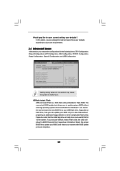
...174;. Just launch this section may set the configurations for CPU CPU Configuration Chipset Configuration ACPI Configuration Storage Configuration PCIPnP Configuration Floppy Configuration SuperIO Configuration USB Configuration BIOS Update Utility ASRock Instant Flash Select Screen Select Item Enter Go to update ... your own requirements. 3.4 Advanced Screen In this option, you are allowed to malfunction. In this section, you execute ASRock Instant Flash utility, the utility will show the BIOS files and their respective information. This convenient BIOS update tool allows ...
...174;. Just launch this section may set the configurations for CPU CPU Configuration Chipset Configuration ACPI Configuration Storage Configuration PCIPnP Configuration Floppy Configuration SuperIO Configuration USB Configuration BIOS Update Utility ASRock Instant Flash Select Screen Select Item Enter Go to update ... your own requirements. 3.4 Advanced Screen In this option, you are allowed to malfunction. In this section, you execute ASRock Instant Flash utility, the utility will show the BIOS files and their respective information. This convenient BIOS update tool allows ...
User Manual
Page 50
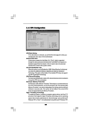
...) can prevent data pages from the chipset. No-Excute Memory Protection No-Execution (NX) Memory Protection Technology is set to keep the CPU from overheated. Hyper Threading Technology To enable this motherboard. The C1 state is unlocked, you changing the ratio value of the system caches...such as Microsoft® Windows® XP or VistaTM. Set to allow you will be hidden if the installed CPU does not support Intel (R) Virtualization Technology. CPU Ratio Setting If the ratio status is supported through the native processor instructions HLT and MWAIT and requires no hardware...
...) can prevent data pages from the chipset. No-Excute Memory Protection No-Execution (NX) Memory Protection Technology is set to keep the CPU from overheated. Hyper Threading Technology To enable this motherboard. The C1 state is unlocked, you changing the ratio value of the system caches...such as Microsoft® Windows® XP or VistaTM. Set to allow you will be hidden if the installed CPU does not support Intel (R) Virtualization Technology. CPU Ratio Setting If the ratio status is supported through the native processor instructions HLT and MWAIT and requires no hardware...
User Manual
Page 51
...Portable/Laptop" to [Enabled]. If you install Windows® XP and select [Auto], you need A20M enabled. Intel (R) C-STATE tech. The CPU C-state is [All]. Configuration options: [All], [1] and [2]. A20M Use this function. Turbo mode allows processor cores to run faster than marked ...allows us to use a hardware coordination mechanism in which each core can switch between multiple frequency and voltage points to the platform and CPU shared resource restrictions. Intel (R) C-STATE tech. to enable or disable A20M. The default value is [Enabled]. Processor can request any...
...Portable/Laptop" to [Enabled]. If you install Windows® XP and select [Auto], you need A20M enabled. Intel (R) C-STATE tech. The CPU C-state is [All]. Configuration options: [All], [1] and [2]. A20M Use this function. Turbo mode allows processor cores to run faster than marked ...allows us to use a hardware coordination mechanism in which each core can switch between multiple frequency and voltage points to the platform and CPU shared resource restrictions. Intel (R) C-STATE tech. to enable or disable A20M. The default value is [Enabled]. Processor can request any...
User Manual
Page 60
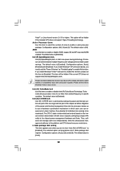
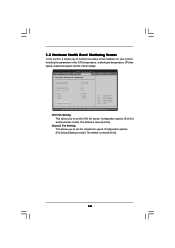
... [Full On]. 60 BIOS SETUP UTILITY Main OC Tweaker Advanced H/W Monitor Boot Security Exit Hardware Health Event Monitoring CPU Temperature M/B Temperature CPU Fan Speed Chassis Fan Speed Power Fan Speed Vcore + 3.30V + 5.00V + 12.00V CPU Fan Setting Chassis Fan Setting : 37 C / 98 F : 31 C / 87 F : N/A : N/A : N/A :... Fan Setting This allows you to monitor the status of the hardware on your system, including the parameters of the CPU temperature, motherboard temperature, CPU fan speed, chassis fan speed, and the critical voltage. Configuration options: [Full On] and [Automatic mode]. 3.5...
... [Full On]. 60 BIOS SETUP UTILITY Main OC Tweaker Advanced H/W Monitor Boot Security Exit Hardware Health Event Monitoring CPU Temperature M/B Temperature CPU Fan Speed Chassis Fan Speed Power Fan Speed Vcore + 3.30V + 5.00V + 12.00V CPU Fan Setting Chassis Fan Setting : 37 C / 98 F : 31 C / 87 F : N/A : N/A : N/A :... Fan Setting This allows you to monitor the status of the hardware on your system, including the parameters of the CPU temperature, motherboard temperature, CPU fan speed, chassis fan speed, and the critical voltage. Configuration options: [Full On] and [Automatic mode]. 3.5...


