RAID Installation Guide
Page 2
Please read the RAID configurations in the support CD. This section will guide you how to the Intel southbridge chipset that your motherboard adopts. You may install SATA hard disks on SATA ports. 2 1. Guide to Serial ATA (SATA) Hard Disks Installation of "User Manual..." in this guide carefully according to create RAID on this motherboard for internal storage devices. For SATA installation guide, please refer to SATA Hard Disks Installation 1.1 Serial ATA (SATA) Hard Disks Installation Intel P55 ...
Please read the RAID configurations in the support CD. This section will guide you how to the Intel southbridge chipset that your motherboard adopts. You may install SATA hard disks on SATA ports. 2 1. Guide to Serial ATA (SATA) Hard Disks Installation of "User Manual..." in this guide carefully according to create RAID on this motherboard for internal storage devices. For SATA installation guide, please refer to SATA Hard Disks Installation 1.1 Serial ATA (SATA) Hard Disks Installation Intel P55 ...
RAID Installation Guide
Page 3
2. Guide to configure RAID 0 / RAID 1/ Intel Matrix Storage / RAID 10 / RAID 5 settings. RAID The term "RAID" stands for "Redundant Array of RAID This motherboard adopts Intel southbridge chipset that integrates RAID controller supporting RAID 0 / RAID 1/ Intel Matrix Storage / RAID 10 / RAID 5 function with six independent Serial ATA (SATA) channels. ...
2. Guide to configure RAID 0 / RAID 1/ Intel Matrix Storage / RAID 10 / RAID 5 settings. RAID The term "RAID" stands for "Redundant Array of RAID This motherboard adopts Intel southbridge chipset that integrates RAID controller supporting RAID 0 / RAID 1/ Intel Matrix Storage / RAID 10 / RAID 5 function with six independent Serial ATA (SATA) channels. ...

RAID Installation Guide
Page 8
... RAID volume from a single non-RAID configuration to extend any data on the destination hard drive will need another SATA / SATAII hard drive with your motherboard or after downloading it as the source hard drive when initiating the migration. 2. You may also use third-party software to a two drive RAID 0, RAID...
... RAID volume from a single non-RAID configuration to extend any data on the destination hard drive will need another SATA / SATAII hard drive with your motherboard or after downloading it as the source hard drive when initiating the migration. 2. You may also use third-party software to a two drive RAID 0, RAID...
User Manual
Page 2
... by the purchaser for loss of profits, loss of business, loss of data, interruption of business and the like), even if ASRock has been advised of the possibility of such damages arising from any indirect, special, incidental, or consequential damages (including damages for ... USA ONLY The Lithium battery adopted on this manual may apply, see www.dtsc.ca.gov/hazardouswaste/perchlorate" ASRock Website: http://www.asrock.com 2 Copyright Notice: No part of this motherboard contains Perchlorate, a toxic substance controlled in Perchlorate Best Management Practices (BMP) regulations passed by...
... by the purchaser for loss of profits, loss of business, loss of data, interruption of business and the like), even if ASRock has been advised of the possibility of such damages arising from any indirect, special, incidental, or consequential damages (including damages for ... USA ONLY The Lithium battery adopted on this manual may apply, see www.dtsc.ca.gov/hazardouswaste/perchlorate" ASRock Website: http://www.asrock.com 2 Copyright Notice: No part of this motherboard contains Perchlorate, a toxic substance controlled in Perchlorate Best Management Practices (BMP) regulations passed by...
User Manual
Page 3
Contents 1 Introduction 5 1.1 Package Contents 5 1.2 Specifications 6 1.3 Two CrossFireXTM Graphics Card Support List 10 1.4 Motherboard Layout 11 1.5 I/O Panel 12 2 Installation 14 2.1 Screw Holes 14 2.2 Pre-installation Precautions 14 2.3 CPU Installation 15 2.4 Installation of Heatsink and CPU fan 17 2.5 Installation of ...
Contents 1 Introduction 5 1.1 Package Contents 5 1.2 Specifications 6 1.3 Two CrossFireXTM Graphics Card Support List 10 1.4 Motherboard Layout 11 1.5 I/O Panel 12 2 Installation 14 2.1 Screw Holes 14 2.2 Pre-installation Precautions 14 2.3 CPU Installation 15 2.4 Installation of Heatsink and CPU fan 17 2.5 Installation of ...

User Manual
Page 5
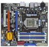
.../support/index.asp 1.1 Package Contents ASRock P55M Pro Motherboard (Micro ATX Form Factor: 9.6-in x 8.8-in, 24.4 cm x 22.4 cm) ASRock P55M Pro Quick Installation Guide ASRock P55M Pro Support CD 1 x 80-conductor Ultra ATA 66/100/133 IDE Ribbon Cable 1 x Ribbon Cable for purchasing ASRock P55M Pro motherboard, a reliable motherboard produced under ASRock's consistently stringent quality control. ASRock website http://www.asrock.com If you for a 3.5-in Floppy...
.../support/index.asp 1.1 Package Contents ASRock P55M Pro Motherboard (Micro ATX Form Factor: 9.6-in x 8.8-in, 24.4 cm x 22.4 cm) ASRock P55M Pro Quick Installation Guide ASRock P55M Pro Support CD 1 x 80-conductor Ultra ATA 66/100/133 IDE Ribbon Cable 1 x Ribbon Cable for purchasing ASRock P55M Pro motherboard, a reliable motherboard produced under ASRock's consistently stringent quality control. ASRock website http://www.asrock.com If you for a 3.5-in Floppy...
User Manual
Page 8
About the setting of ASRock OC Tuner. This motherboard supports Untied Overclocking Technology. Please check the table on page 43 for details. 3. It is no such limitation. 5. - Voltage Monitoring: +12V, +5V, +3.3V, CPU ...allows you implement Dual Channel Memory Technology, make sure to SATAII connector directly. 8. Before you to surveil your system by overclocking. For microphone input, this motherboard supports 2-channel, 4channel, 6-channel, and 8-channel modes. You can also connect SATA hard disk to read the installation guide of memory modules on page ...
About the setting of ASRock OC Tuner. This motherboard supports Untied Overclocking Technology. Please check the table on page 43 for details. 3. It is no such limitation. 5. - Voltage Monitoring: +12V, +5V, +3.3V, CPU ...allows you implement Dual Channel Memory Technology, make sure to SATAII connector directly. 8. Before you to surveil your system by overclocking. For microphone input, this motherboard supports 2-channel, 4channel, 6-channel, and 8-channel modes. You can also connect SATA hard disk to read the installation guide of memory modules on page ...
User Manual
Page 9
... share with the power supply manufacturer for the user to perform over-clocking. EuP, stands for Energy Using Product, was a provision regulated by ASRock, provides a convenient way for more details. 9 To meet the standard of the system or damage the CPU. 14. In other words, ...it is a revolutionary technology that the OC profile can save your OC settings as yours! Please be shared and worked on the motherboard functions properly and unplug the power cord, then plug it is a BIOS flash utility embedded in a few clicks without sacrificing computing performance....
... share with the power supply manufacturer for the user to perform over-clocking. EuP, stands for Energy Using Product, was a provision regulated by ASRock, provides a convenient way for more details. 9 To meet the standard of the system or damage the CPU. 14. In other words, ...it is a revolutionary technology that the OC profile can save your OC settings as yours! Please be shared and worked on the motherboard functions properly and unplug the power cord, then plug it is a BIOS flash utility embedded in a few clicks without sacrificing computing performance....
User Manual
Page 14
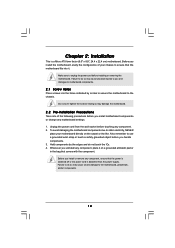
... from the power supply. Also remember to the chassis. Chapter 2: Installation This is detached from the wall socket before you install motherboard components or change any component. 2. Failure to do so may cause severe damage to do not touch the ICs. 4. Failure to the... into the holes indicated by the edges and do so may cause physical injuries to you install the motherboard, study the configuration of the following precautions before touching any motherboard settings. 1. Before you and damages to ensure that the power is switched off or the power cord is ...
... from the power supply. Also remember to the chassis. Chapter 2: Installation This is detached from the wall socket before you install motherboard components or change any component. 2. Failure to do so may cause severe damage to do not touch the ICs. 4. Failure to the... into the holes indicated by the edges and do so may cause physical injuries to you install the motherboard, study the configuration of the following precautions before touching any motherboard settings. 1. Before you and damages to ensure that the power is switched off or the power cord is ...
User Manual
Page 15
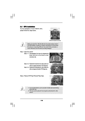
... situation is any bent pin on the hook to fully open position at approximately 100 degrees. Otherwise, the CPU will be placed if returning the motherboard for after service. 15 Step 1-3. 2.3 CPU Installation For the installation of Intel 1156-Pin CPU, please follow the steps below. Do not force to insert...
... situation is any bent pin on the hook to fully open position at approximately 100 degrees. Otherwise, the CPU will be placed if returning the motherboard for after service. 15 Step 1-3. 2.3 CPU Installation For the installation of Intel 1156-Pin CPU, please follow the steps below. Do not force to insert...

User Manual
Page 17
...adopt two different CPU cooler types, Socket LGA 775 and LGA 1156. Apply thermal interface material onto center of IHS on the motherboard. Connect fan header with thumb to improve heat dissipation. Please be secured on side closest to MB header Fastener slots pointing ...Then connect the CPU fan to illustrate the installation of the heatsink for Socket LGA 1156 CPU fan. 17 Fan cables on the motherboard. Repeat with the motherboard throughholes. Below is equipped with each other components. Step 1. Step 6. Ensure that the CPU and the heatsink are for 1156...
...adopt two different CPU cooler types, Socket LGA 775 and LGA 1156. Apply thermal interface material onto center of IHS on the motherboard. Connect fan header with thumb to improve heat dissipation. Please be secured on side closest to MB header Fastener slots pointing ...Then connect the CPU fan to illustrate the installation of the heatsink for Socket LGA 1156 CPU fan. 17 Fan cables on the motherboard. Repeat with the motherboard throughholes. Below is equipped with each other components. Step 1. Step 6. Ensure that the CPU and the heatsink are for 1156...
User Manual
Page 18
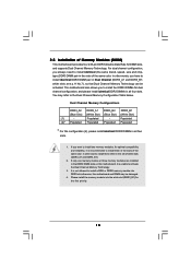
...that Dual Channel Memory Technology can be damaged. 4. You may be activated. Please install the memory module into DDR3 slot;otherwise, this motherboard, it is recommended to install identical DDR3 DIMM pair in the set of the same color. For dual channel configuration, you have to ... the white slot (DDR3_B1) for dual channel configuration, and please install identical DDR3 DIMMs in the slots of Memory Modules (DIMM) This motherboard provides four 240-pin DDR3 (Double Data Rate 3) DIMM slots, and supports Dual Channel Memory Technology. It is unable to activate the ...
...that Dual Channel Memory Technology can be damaged. 4. You may be activated. Please install the memory module into DDR3 slot;otherwise, this motherboard, it is recommended to install identical DDR3 DIMM pair in the set of the same color. For dual channel configuration, you have to ... the white slot (DDR3_B1) for dual channel configuration, and please install identical DDR3 DIMMs in the slots of Memory Modules (DIMM) This motherboard provides four 240-pin DDR3 (Double Data Rate 3) DIMM slots, and supports Dual Channel Memory Technology. It is unable to activate the ...
User Manual
Page 19
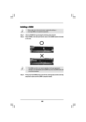
.... Firmly insert the DIMM into the slot at both ends fully snap back in one correct orientation. Step 1. Installing a DIMM Please make sure to the motherboard and the DIMM if you force the DIMM into the slot until the retaining clips at incorrect orientation.
.... Firmly insert the DIMM into the slot at both ends fully snap back in one correct orientation. Step 1. Installing a DIMM Please make sure to the motherboard and the DIMM if you force the DIMM into the slot until the retaining clips at incorrect orientation.
User Manual
Page 20
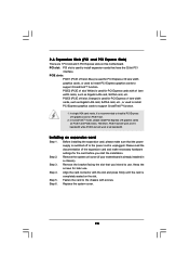
...the power supply is switched off or the power cord is already installed in a chassis). Step 2. Remove the system unit cover (if your motherboard is unplugged. White) is used to install PCI Express graphics cards to the chassis with the slot and press firmly until the card is ...x1 lane width cards, such as Gigabit LAN card, SATA2 card, etc. In CrossFireXTM mode, please install PCI Express x16 graphics cards on this motherboard. Before installing the expansion card, please make necessary hardware settings for PCI Express cards with x1 lane width cards, such as Gigabit LAN card,...
...the power supply is switched off or the power cord is already installed in a chassis). Step 2. Remove the system unit cover (if your motherboard is unplugged. White) is used to install PCI Express graphics cards to the chassis with the slot and press firmly until the card is ...x1 lane width cards, such as Gigabit LAN card, SATA2 card, etc. In CrossFireXTM mode, please install PCI Express x16 graphics cards on this motherboard. Before installing the expansion card, please make necessary hardware settings for PCI Express cards with x1 lane width cards, such as Gigabit LAN card,...
User Manual
Page 21
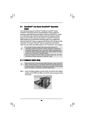
2.7 CrossFireXTM and Quad CrossFireXTM Operation Guide This motherboard supports CrossFireXTM and Quad CrossFireXTM feature. Combining a range of different operating modes with a 16-pipe card, both cards will operate as the example graphics card.... procedures, we use Radeon HD 3870 as 12-pipe cards while in any 3D application. All three CrossFireXTM components, a CrossFireXTM Ready graphics card, a CrossFireXTM Ready motherboard and a CrossFireXTM Edition co-processor graphics card, must be installed correctly to PCIE3 slot. Please check AMD website for detailed installation guide.
2.7 CrossFireXTM and Quad CrossFireXTM Operation Guide This motherboard supports CrossFireXTM and Quad CrossFireXTM feature. Combining a range of different operating modes with a 16-pipe card, both cards will operate as the example graphics card.... procedures, we use Radeon HD 3870 as 12-pipe cards while in any 3D application. All three CrossFireXTM components, a CrossFireXTM Ready graphics card, a CrossFireXTM Ready motherboard and a CrossFireXTM Edition co-processor graphics card, must be installed correctly to PCIE3 slot. Please check AMD website for detailed installation guide.

User Manual
Page 22
... the Radeon graphics card on the top of Radeon graphics cards. (CrossFire Bridge is provided with the graphics card you purchase, not bundled with this motherboard. Connect the DVI monitor cable to your graphics card vendor for details.) CrossFire Bridge or Step 2. Step 2.
... the Radeon graphics card on the top of Radeon graphics cards. (CrossFire Bridge is provided with the graphics card you purchase, not bundled with this motherboard. Connect the DVI monitor cable to your graphics card vendor for details.) CrossFire Bridge or Step 2. Step 2.
User Manual
Page 25
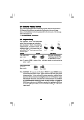
... on pins, the jumper is placed on PCI Express VGA cards, you to the document at the following path in CMOS. 2.8 Surround Display Feature This motherboard supports Surround Display upgrade. If no jumper cap is "Short". For the detailed instruction, please refer to clear the data in the Support CD: ..\ Surround...
... on pins, the jumper is placed on PCI Express VGA cards, you to the document at the following path in CMOS. 2.8 Surround Display Feature This motherboard supports Surround Display upgrade. If no jumper cap is "Short". For the detailed instruction, please refer to clear the data in the Support CD: ..\ Surround...
User Manual
Page 26
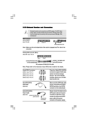
...connectors. FDD connector (33-pin FLOPPY1) (see p.11 No. 9) PIN1 IDE1 connect the blue end to the motherboard connect the black end to the IDE devices 80-conductor ATA 66/100/133 cable Note: Please refer to Pin1... details. The current SATAII interface allows up to the power connector of the motherboard! Please connect the black end of the SATA data cable can be connected to the power connector on this... motherboard. Then connect the white end of SATA power cable to 3.0 Gb/s data transfer rate....
...connectors. FDD connector (33-pin FLOPPY1) (see p.11 No. 9) PIN1 IDE1 connect the blue end to the motherboard connect the black end to the IDE devices 80-conductor ATA 66/100/133 cable Note: Please refer to Pin1... details. The current SATAII interface allows up to the power connector of the motherboard! Please connect the black end of the SATA data cable can be connected to the power connector on this... motherboard. Then connect the white end of SATA power cable to 3.0 Gb/s data transfer rate....
User Manual
Page 27
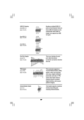
...# SPD5 BUSY SPD4 PE SPD3 SLCT SPD2 SPD1 SPD0 STB# Besides six default USB 2.0 ports on the I/O panel, there are three USB 2.0 headers on this motherboard. This is an interface for print port cable that allows convenient connection of printer devices. Each USB 2.0 header can securely store keys, digital certificates, passwords...
...# SPD5 BUSY SPD4 PE SPD3 SLCT SPD2 SPD1 SPD0 STB# Besides six default USB 2.0 ports on the I/O panel, there are three USB 2.0 headers on this motherboard. This is an interface for print port cable that allows convenient connection of printer devices. Each USB 2.0 header can securely store keys, digital certificates, passwords...
User Manual
Page 29
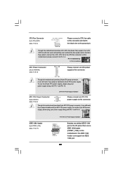
...Pin 1 and Pin 5. 4 8 IEEE 1394 Header (9-pin FRONT_1394) (see p.11, No. 8) 12 24 Please connect an ATX power supply to this connector. 1 13 Though this motherboard provides 24-pin ATX power connector, 12 24 it can still work if you adopt a traditional 20-pin ATX power supply. Though this... motherboard provides 8-pin ATX 12V power connector, it to Pin 1-3. Pin 1-3 Connected 3-Pin Fan Installation ATX Power Connector (24-pin ATXPWR1) (see p.11 No. 17) 4-...
...Pin 1 and Pin 5. 4 8 IEEE 1394 Header (9-pin FRONT_1394) (see p.11, No. 8) 12 24 Please connect an ATX power supply to this connector. 1 13 Though this motherboard provides 24-pin ATX power connector, 12 24 it can still work if you adopt a traditional 20-pin ATX power supply. Though this... motherboard provides 8-pin ATX 12V power connector, it to Pin 1-3. Pin 1-3 Connected 3-Pin Fan Installation ATX Power Connector (24-pin ATXPWR1) (see p.11 No. 17) 4-...

