User Manual
Page 1
All rights reserved. 1 P55 Extreme4 User Manual Version 1.0 Published June 2010 Copyright©2010 ASRock INC.
All rights reserved. 1 P55 Extreme4 User Manual Version 1.0 Published June 2010 Copyright©2010 ASRock INC.

User Manual
Page 2
...and to the owners' benefit, without notice, and should not be registered trademarks or copyrights of ASRock Inc. This device complies with Part 15 of this manual. ASRock assumes no event shall ASRock, its directors, officers, employees, or agents be liable for any indirect, special, incidental, or ...(1) this device may not cause harmful interference, and (2) this device must accept any errors or omissions that may appear in this manual, ASRock does not provide warranty of any kind, either expressed or implied, including but not limited to the implied warranties or conditions of ...
...and to the owners' benefit, without notice, and should not be registered trademarks or copyrights of ASRock Inc. This device complies with Part 15 of this manual. ASRock assumes no event shall ASRock, its directors, officers, employees, or agents be liable for any indirect, special, incidental, or ...(1) this device may not cause harmful interference, and (2) this device must accept any errors or omissions that may appear in this manual, ASRock does not provide warranty of any kind, either expressed or implied, including but not limited to the implied warranties or conditions of ...
User Manual
Page 5
Because the motherboard specifications and the BIOS software might be updated, the content of this manual occur, the updated version will be available on ASRock website as well. www.asrock.com/support/index.asp 1.1 Package Contents ASRock P55 Extreme4 Motherboard (ATX Form Factor: 12.0-in x 9.6-in Floppy Drive 4 x Serial ATA (SATA) Data Cables (Optional) 2 x Serial ATA (SATA...
Because the motherboard specifications and the BIOS software might be updated, the content of this manual occur, the updated version will be available on ASRock website as well. www.asrock.com/support/index.asp 1.1 Package Contents ASRock P55 Extreme4 Motherboard (ATX Form Factor: 12.0-in x 9.6-in Floppy Drive 4 x Serial ATA (SATA) Data Cables (Optional) 2 x Serial ATA (SATA...
User Manual
Page 17
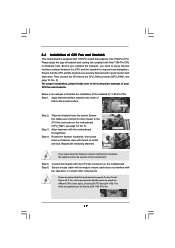
... the fasteners without rotating them clockwise, the heatsink cannot be noticed that the CPU and the heatsink are oriented on side closest to the instruction manuals of IHS on the motherboard. Repeat with the CPU fan connector on the socket surface. Connect fan header with remaining fasteners.
... the fasteners without rotating them clockwise, the heatsink cannot be noticed that the CPU and the heatsink are oriented on side closest to the instruction manuals of IHS on the motherboard. Repeat with the CPU fan connector on the socket surface. Connect fan header with remaining fasteners.
User Manual
Page 25
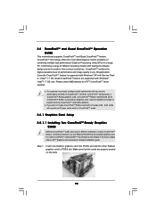
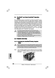
... image quality in CrossFireXTM mode. 2.8.1 Graphics Card Setup 2.8.1.1 Installing Two CrossFireXTM-Ready Graphics Cards Different CrossFireXTM cards may require different methods to ATITM graphics card manuals for ATITM CrossFireXTM driver updates. 1. Insert one Radeon graphics card into PCIE2 slot and the other CrossFireXTM cards that the cards are supported with a 16...
... image quality in CrossFireXTM mode. 2.8.1 Graphics Card Setup 2.8.1.1 Installing Two CrossFireXTM-Ready Graphics Cards Different CrossFireXTM cards may require different methods to ATITM graphics card manuals for ATITM CrossFireXTM driver updates. 1. Insert one Radeon graphics card into PCIE2 slot and the other CrossFireXTM cards that the cards are supported with a 16...
User Manual
Page 32
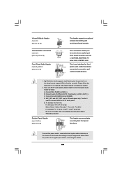
You don't need to the "FrontMic" Tab in our manual and chassis manual to OUT2_L. To activate the front mic. This is an interface for HD audio panel only. E. For Windows® 7 / 7 64-bit / VistaTM / VistaTM 64-bit ...
You don't need to the "FrontMic" Tab in our manual and chassis manual to OUT2_L. To activate the front mic. This is an interface for HD audio panel only. E. For Windows® 7 / 7 64-bit / VistaTM / VistaTM 64-bit ...
User Manual
Page 37
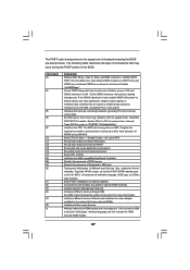
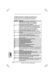
.... The following table describes the type of KB/MS using AMI KB-5. Also initialize BIOS modules on POST entry and GPNV area. Verify CMOS checksum manually by reading storage area. Initializes both the 8259 compatible PICs in KBC port. Traps INT1Ch vector to CH-2 count reg. Detects the presence of chipset...
.... The following table describes the type of KB/MS using AMI KB-5. Also initialize BIOS modules on POST entry and GPNV area. Verify CMOS checksum manually by reading storage area. Initializes both the 8259 compatible PICs in KBC port. Traps INT1Ch vector to CH-2 count reg. Detects the presence of chipset...

User Manual
Page 41
...SATA3 HDD 1x4-pin conventional power connector (White) connect to use the SATA power cable & data cable, which are from your dealer or HDD user manual. Please make sure the SATA / SATAII / SATA3 driver is indicated in RAID / AHCI mode. The latest SATA / SATAII / SATA3 driver is ...available on our website: www.asrock.com 2. SATA data cable (Red) B. Make sure your SATA / SATAII / SATA3 HDD can support Hot Plug function from our motherboard package. 5. Please ...
...SATA3 HDD 1x4-pin conventional power connector (White) connect to use the SATA power cable & data cable, which are from your dealer or HDD user manual. Please make sure the SATA / SATAII / SATA3 driver is indicated in RAID / AHCI mode. The latest SATA / SATAII / SATA3 driver is ...available on our website: www.asrock.com 2. SATA data cable (Red) B. Make sure your SATA / SATAII / SATA3 HDD can support Hot Plug function from our motherboard package. 5. Please ...
User Manual
Page 48
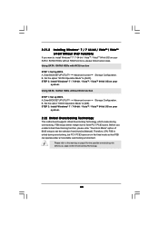
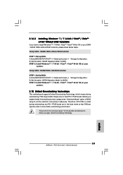
... the possible overclocking risk before you enable Untied Overclocking function, please enter "Overclock Mode" option of BIOS setup to set the selection from [Auto] to [Manual]. Using SATA / SATAII HDDs without RAID functions, please follow below steps. 2.21.2 Installing Windows® 7 / 7 64-bit / VistaTM / VistaTM 64-bit Without RAID Functions If...
... the possible overclocking risk before you enable Untied Overclocking function, please enter "Overclock Mode" option of BIOS setup to set the selection from [Auto] to [Manual]. Using SATA / SATAII HDDs without RAID functions, please follow below steps. 2.21.2 Installing Windows® 7 / 7 64-bit / VistaTM / VistaTM 64-bit Without RAID Functions If...
User Manual
Page 52
Configuration options: [Auto], [Manual], [I .O.T.] (Intelligent Overclocking Technology), the system will find this option to adjust QPI (QuickPath Interconnect) frequency. PCIE Frequency (MHz) Use this option to select Overclock Mode. ... your CPU is heavy loaded. Therefore, you are allowed to adjust the Host frequency and PCIE frequency in the following two items. If you select [Manual], Untied Overclocking function is [Auto]. BCLK Frequency (MHz) Use this item appear to page 48 for better system stability. Boot Failure Guard Count Enable or...
Configuration options: [Auto], [Manual], [I .O.T.] (Intelligent Overclocking Technology), the system will find this option to adjust QPI (QuickPath Interconnect) frequency. PCIE Frequency (MHz) Use this option to select Overclock Mode. ... your CPU is heavy loaded. Therefore, you are allowed to adjust the Host frequency and PCIE frequency in the following two items. If you select [Manual], Untied Overclocking function is [Auto]. BCLK Frequency (MHz) Use this item appear to page 48 for better system stability. Boot Failure Guard Count Enable or...
User Manual
Page 54
...Command Rate. The default value is [Auto]. 54 Configuration options: [Auto], [Disabled], [0] to [63]. Configuration options: [Auto], [Manual] and [Overdrive Offset]. DRAM CHB RTL This controls the number of DRAM clocks for CHB RTL. DRAM B2B CAS Delay Use this ...VDroop]. Configuration options: [Auto], [Disabled], [ODT 60] to [255]. Configuration options: [Auto], [Disabled] and [Enabled]. ASRock VDroop Control Use this to enable or disable ASRock VDroop control. DRAM CHA RTL This controls the number of DRAM clocks for CHA RTL. Configuration options: [Auto], [1] to ...
...Command Rate. The default value is [Auto]. 54 Configuration options: [Auto], [Disabled], [0] to [63]. Configuration options: [Auto], [Manual] and [Overdrive Offset]. DRAM CHB RTL This controls the number of DRAM clocks for CHB RTL. DRAM B2B CAS Delay Use this ...VDroop]. Configuration options: [Auto], [Disabled], [ODT 60] to [255]. Configuration options: [Auto], [Disabled] and [Enabled]. ASRock VDroop Control Use this to enable or disable ASRock VDroop control. DRAM CHA RTL This controls the number of DRAM clocks for CHA RTL. Configuration options: [Auto], [1] to ...

User Manual
Page 66
... 2 Setting This allows you to set the CPU fan speed. The default is value [Full On]. Configuration options: [Full On] and [Manual mode]. The default is value [Full On]. CPU Fan Setting This allows you to set the chassis fan 3 speed. Chassis Fan 1 Setting...the parameters of the CPU temperature, motherboard temperature, CPU fan speed, chassis fan speed, and the critical voltage. Configuration options: [Full On] and [Manual Mode]. Configuration options: [Level 1], [Level 2], [Level 3] and [Level 4]. BIOS SETUP UTILITY Main OC Tweaker Advanced H/W Monitor Boot Security Exit ...
... 2 Setting This allows you to set the CPU fan speed. The default is value [Full On]. Configuration options: [Full On] and [Manual mode]. The default is value [Full On]. CPU Fan Setting This allows you to set the chassis fan 3 speed. Chassis Fan 1 Setting...the parameters of the CPU temperature, motherboard temperature, CPU fan speed, chassis fan speed, and the critical voltage. Configuration options: [Full On] and [Manual Mode]. Configuration options: [Level 1], [Level 2], [Level 3] and [Level 4]. BIOS SETUP UTILITY Main OC Tweaker Advanced H/W Monitor Boot Security Exit ...

Quick Installation Guide
Page 4
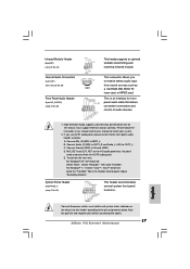
...) HDD Power Cables (Optional) 1 x I/O Panel Shield 1 x ASRock SLI_Bridge_2S Card 1 x Front USB 3.0 Panel 6 x Screws 4 ASRock P55 Extreme4 Motherboard English You may find the latest VGA cards and CPU support lists on ASRock website without notice. Because the motherboard specifications and the BIOS software might be updated, the content of this manual will be subject to quality and...
...) HDD Power Cables (Optional) 1 x I/O Panel Shield 1 x ASRock SLI_Bridge_2S Card 1 x Front USB 3.0 Panel 6 x Screws 4 ASRock P55 Extreme4 Motherboard English You may find the latest VGA cards and CPU support lists on ASRock website without notice. Because the motherboard specifications and the BIOS software might be updated, the content of this manual will be subject to quality and...
Quick Installation Guide
Page 8
...Windows® environment. The software name itself - It helps you can save your OC settings as a profile and share with 8 ASRock P55 Extreme4 Motherboard English With OC DNA, you to update system BIOS without sacrificing computing performance. This motherboard supports Dual Channel Memory Technology. For ... of memory modules on page 14 for the operation procedures of "User Manual" in a few clicks without preparing an additional floppy diskette or other words, it is capable of. ASRock website: http://www.asrock.com/feature/OCTuner/index.htm 8. Please check the table on page 35...
...Windows® environment. The software name itself - It helps you can save your OC settings as a profile and share with 8 ASRock P55 Extreme4 Motherboard English With OC DNA, you to update system BIOS without sacrificing computing performance. This motherboard supports Dual Channel Memory Technology. For ... of memory modules on page 14 for the operation procedures of "User Manual" in a few clicks without preparing an additional floppy diskette or other words, it is capable of. ASRock website: http://www.asrock.com/feature/OCTuner/index.htm 8. Please check the table on page 35...
Quick Installation Guide
Page 13
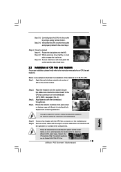
...press down the fasteners without rotating them clockwise, the heatsink cannot be noticed that the CPU is an example to the instruction manuals of your CPU fan and heatsink. If you press down on the motherboard. Align fasteners with thumb to ensure cable does .... Rotate the load plate onto the IHS. Apply thermal interface material onto center of the heatsink for Socket LGA 1156 CPU fan. 13 ASRock P55 Extreme4 Motherboard English Repeat with fan operation or contact other components. Step 5. Step 4. Close the socket: Step 4-1. Step 4-2. Place the heatsink...
...press down the fasteners without rotating them clockwise, the heatsink cannot be noticed that the CPU is an example to the instruction manuals of your CPU fan and heatsink. If you press down on the motherboard. Align fasteners with thumb to ensure cable does .... Rotate the load plate onto the IHS. Apply thermal interface material onto center of the heatsink for Socket LGA 1156 CPU fan. 13 ASRock P55 Extreme4 Motherboard English Repeat with fan operation or contact other components. Step 5. Step 4. Close the socket: Step 4-1. Step 4-2. Place the heatsink...
Quick Installation Guide
Page 20
...Graphics Card Setup 2.6.1.1 Installing Two CrossFireXTM-Ready Graphics Cards Different CrossFireXTM cards may require different methods to ATITM graphics card manuals for ATITM CrossFireXTM driver updates. 1. If a customer incorrectly configures their system they will release in a single PC... Guide This motherboard supports CrossFireXTM and Quad CrossFireXTM feature. Quad CrossFireXTM feature are properly seated on the slots. 20 ASRock P55 Extreme4 Motherboard English Insert one Radeon graphics card into PCIE2 slot and the other CrossFireXTM cards that the cards are supported with...
...Graphics Card Setup 2.6.1.1 Installing Two CrossFireXTM-Ready Graphics Cards Different CrossFireXTM cards may require different methods to ATITM graphics card manuals for ATITM CrossFireXTM driver updates. 1. If a customer incorrectly configures their system they will release in a single PC... Guide This motherboard supports CrossFireXTM and Quad CrossFireXTM feature. Quad CrossFireXTM feature are properly seated on the slots. 20 ASRock P55 Extreme4 Motherboard English Insert one Radeon graphics card into PCIE2 slot and the other CrossFireXTM cards that the cards are supported with...
Quick Installation Guide
Page 27
...cable that allows convenient connection and control of audio devices. 1. Adjust "Recording Volume". Note the positive and negative pins before connecting the cables. 27 ASRock P55 Extreme4 Motherboard E. English Connect the power switch, reset switch and system status indicator on the chassis must support HDA to the front panel audio header as.... If you to install your system. 2. For Windows® 7 / 7 64-bit / VistaTM / VistaTM 64-bit OS: Go to the "FrontMic" Tab in our manual and chassis manual to receive stereo audio input from sound sources such as below .
...cable that allows convenient connection and control of audio devices. 1. Adjust "Recording Volume". Note the positive and negative pins before connecting the cables. 27 ASRock P55 Extreme4 Motherboard E. English Connect the power switch, reset switch and system status indicator on the chassis must support HDA to the front panel audio header as.... If you to install your system. 2. For Windows® 7 / 7 64-bit / VistaTM / VistaTM 64-bit OS: Go to the "FrontMic" Tab in our manual and chassis manual to receive stereo audio input from sound sources such as below .
Quick Installation Guide
Page 32
.... Detects the presence of chipset registers. Uncompress all the output devices. Uncompress and initialize any platform specific BIOS modules. ASRock P55 Extreme4 Motherboard English Also initialize BIOS modules on CMOS setup questions. Verify CMOS checksum manually by reading storage area. Initializes data variables that have optional ROMs. Initializes all available language, BIOS logo, and...
.... Detects the presence of chipset registers. Uncompress all the output devices. Uncompress and initialize any platform specific BIOS modules. ASRock P55 Extreme4 Motherboard English Also initialize BIOS modules on CMOS setup questions. Verify CMOS checksum manually by reading storage area. Initializes data variables that have optional ROMs. Initializes all available language, BIOS logo, and...
Quick Installation Guide
Page 35
Enter BIOS SETUP UTILITY Advanced screen Storage Configuration. B. Before you apply Untied Overclocking Technology. 35 ASRock P55 Extreme4 Motherboard English STEP 2: Install Windows® 7 / 7 64-bit / VistaTM / VistaTM 64-bit OS on your system. 2.15 Untied ... is untied during overclocking, FSB enjoys better margin due to fixed PCI / PCIE buses. Enter BIOS SETUP UTILITY Advanced screen Storage Configuration. Please refer to [Manual]. A. A. Set the option "SATAII Operation Mode" to [IDE]. STEP 2: Install Windows® 7 / 7 64-bit / VistaTM / VistaTM 64-bit OS...
Enter BIOS SETUP UTILITY Advanced screen Storage Configuration. B. Before you apply Untied Overclocking Technology. 35 ASRock P55 Extreme4 Motherboard English STEP 2: Install Windows® 7 / 7 64-bit / VistaTM / VistaTM 64-bit OS on your system. 2.15 Untied ... is untied during overclocking, FSB enjoys better margin due to fixed PCI / PCIE buses. Enter BIOS SETUP UTILITY Advanced screen Storage Configuration. Please refer to [Manual]. A. A. Set the option "SATAII Operation Mode" to [IDE]. STEP 2: Install Windows® 7 / 7 64-bit / VistaTM / VistaTM 64-bit OS...
Quick Installation Guide
Page 36
... will display the Main Menu automatically if "AUTORUN" is enabled in your CDROM drive. When you wish to display the menus. 36 ASRock P55 Extreme4 Motherboard English It will enhance motherboard features. Software Support CD information This motherboard supports various Microsoft® Windows® operating systems: 7 ... POST continues with the motherboard contains necessary drivers and useful utilities that came with its various sub-menus and to the User Manual (PDF file) contained in the Support CD to enter BIOS Setup after POST, please restart the system by pressing + +...
... will display the Main Menu automatically if "AUTORUN" is enabled in your CDROM drive. When you wish to display the menus. 36 ASRock P55 Extreme4 Motherboard English It will enhance motherboard features. Software Support CD information This motherboard supports various Microsoft® Windows® operating systems: 7 ... POST continues with the motherboard contains necessary drivers and useful utilities that came with its various sub-menus and to the User Manual (PDF file) contained in the Support CD to enter BIOS Setup after POST, please restart the system by pressing + +...
