
Intel Rapid Storage Guide
Page 12
... setup. Unless you have selected RAID 1, use the up or down arrow keys to enter the option ROM user interface. 2. Press Enter to enter the BIOS Setup program after the Power-On-Self-Test (POST) memory test begins. 2. Click F2 or Delete to select the physical disks. 6. Enetr the Advanced ... onto a RAID volume (F6 install method) In order to install an operating system onto a RAID volume, the RAID option must be enabled in the system BIOS, a RAID volume must be created, and the F6 installation method must be used to load the Intel® Rapid Storage Technology driver during POST, press...
... setup. Unless you have selected RAID 1, use the up or down arrow keys to enter the option ROM user interface. 2. Press Enter to enter the BIOS Setup program after the Power-On-Self-Test (POST) memory test begins. 2. Click F2 or Delete to select the physical disks. 6. Enetr the Advanced ... onto a RAID volume (F6 install method) In order to install an operating system onto a RAID volume, the RAID option must be enabled in the system BIOS, a RAID volume must be created, and the F6 installation method must be used to load the Intel® Rapid Storage Technology driver during POST, press...
Marvell SATA3 RAID Installation Guide
Page 12
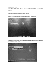
Press . 12 In Marvell BIOS Setup screen, select free disks to create array and continue to enter Marvell BIOS Setup screen. First of all, you can also use Marvell RAID ROM to configure RAID functions. Marvell RAID ROM Besides Marvell SATA3 RAID utility, you need to make a SATA3 driver diskette. Press + during the POST to create virtual disk on this array.
Press . 12 In Marvell BIOS Setup screen, select free disks to create array and continue to enter Marvell BIOS Setup screen. First of all, you can also use Marvell RAID ROM to configure RAID functions. Marvell RAID ROM Besides Marvell SATA3 RAID utility, you need to make a SATA3 driver diskette. Press + during the POST to create virtual disk on this array.
Marvell SATA3 RAID Installation Guide
Page 15
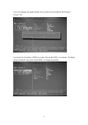
You will ask "Do you create. The Status shows "Functional" now, which means RAID 1 is created successfully. 15 In the exit message, the system will see the information of RAID you want to exit from Marvell BIOS Setup?" Here we take RAID 1 for example. Choose "Yes".
You will ask "Do you create. The Status shows "Functional" now, which means RAID 1 is created successfully. 15 In the exit message, the system will see the information of RAID you want to exit from Marvell BIOS Setup?" Here we take RAID 1 for example. Choose "Yes".
User Manual
Page 4
... RAID Functions 47 2.21.2 Installing Windows® 7 / 7 64-bit / VistaTM / VistaTM 64-bit Without RAID Functions 48 2.22 Untied Overclocking Technology 48 3 BIOS SETUP UTILITY 49 3.1 Introduction 49 3.1.1 BIOS Menu Bar 49 3.1.2 Navigation Keys 50 3.2 Main Screen 50 3.3 OC Tweaker Screen 51 3.4 Advanced Screen 56 3.4.1 CPU Configuration 57 3.4.2 Chipset Configuration 59 3.4.3 ACPI...
... RAID Functions 47 2.21.2 Installing Windows® 7 / 7 64-bit / VistaTM / VistaTM 64-bit Without RAID Functions 48 2.22 Untied Overclocking Technology 48 3 BIOS SETUP UTILITY 49 3.1 Introduction 49 3.1.1 BIOS Menu Bar 49 3.1.2 Navigation Keys 50 3.2 Main Screen 50 3.3 OC Tweaker Screen 51 3.4 Advanced Screen 56 3.4.1 CPU Configuration 57 3.4.2 Chipset Configuration 59 3.4.3 ACPI...
User Manual
Page 5
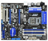
... ASRock P55 Extreme4 Motherboard (ATX Form Factor: 12.0-in x 9.6-in, 30.5 cm x 24.4 cm) ASRock P55 Extreme4 Quick Installation Guide ASRock P55 Extreme4 Support CD 1 x 80-conductor Ultra ATA 66/100/133 IDE Ribbon Cable 1 x Ribbon Cable for purchasing ASRock P55 Extreme4 motherboard, a reliable motherboard produced under ASRock's consistently stringent quality control. It delivers excellent performance with robust design conforming to ASRock's commitment to BIOS...
... ASRock P55 Extreme4 Motherboard (ATX Form Factor: 12.0-in x 9.6-in, 30.5 cm x 24.4 cm) ASRock P55 Extreme4 Quick Installation Guide ASRock P55 Extreme4 Support CD 1 x 80-conductor Ultra ATA 66/100/133 IDE Ribbon Cable 1 x Ribbon Cable for purchasing ASRock P55 Extreme4 motherboard, a reliable motherboard produced under ASRock's consistently stringent quality control. It delivers excellent performance with robust design conforming to ASRock's commitment to BIOS...
User Manual
Page 7
... to -Use USB 3.0 Ports - 1 x eSATAIII Connector - 1 x RJ-45 LAN Port with LED (ACT/LINK LED and SPEED LED) - 1 x Clear CMOS Switch with LED - 16Mb AMI BIOS - Front panel audio connector - 3 x USB 2.0 headers (support 6 USB 2.0 ports) - 1 x USB 3.0 header (supports 2 USB 3.0 ports) - 1 x Dr. Debug (7-Segment Debug LED) - 1 x ...with LED - Supports "Plug and Play" - HD Audio Jack: Side Speaker/Rear Speaker/Central/Bass/ Line in header - AMI Legal BIOS - ACPI 1.1 Compliance Wake Up Events 7 CPU/Chassis/Power FAN connector - 24 pin ATX power connector - 8 pin 12V power connector -
... to -Use USB 3.0 Ports - 1 x eSATAIII Connector - 1 x RJ-45 LAN Port with LED (ACT/LINK LED and SPEED LED) - 1 x Clear CMOS Switch with LED - 16Mb AMI BIOS - Front panel audio connector - 3 x USB 2.0 headers (support 6 USB 2.0 ports) - 1 x USB 3.0 header (supports 2 USB 3.0 ports) - 1 x Dr. Debug (7-Segment Debug LED) - 1 x ...with LED - Supports "Plug and Play" - HD Audio Jack: Side Speaker/Rear Speaker/Central/Bass/ Line in header - AMI Legal BIOS - ACPI 1.1 Compliance Wake Up Events 7 CPU/Chassis/Power FAN connector - 24 pin ATX power connector - 8 pin 12V power connector -

User Manual
Page 8
.../ VistaTM / VistaTM 64-bit / XP / XP 64-bit compliant Certifications - Drivers, Utilities, AntiVirus Software (Trial Version), ASRock Software Suite (CyberLink DVD Suite - ASRock Instant Flash (see CAUTION 8) - OEM) Unique Feature - Intelligent Energy Saver (see CAUTION 9) - Turbo 40 / Turbo 50... detailed product information, please visit our website: http://www.asrock.com WARNING Please realize that there is a certain risk involved with overclocking, including adjusting the setting in the BIOS, applying Untied Overclocking Technology, or using the thirdparty overclocking ...
.../ VistaTM / VistaTM 64-bit / XP / XP 64-bit compliant Certifications - Drivers, Utilities, AntiVirus Software (Trial Version), ASRock Software Suite (CyberLink DVD Suite - ASRock Instant Flash (see CAUTION 8) - OEM) Unique Feature - Intelligent Energy Saver (see CAUTION 9) - Turbo 40 / Turbo 50... detailed product information, please visit our website: http://www.asrock.com WARNING Please realize that there is a certain risk involved with overclocking, including adjusting the setting in the BIOS, applying Untied Overclocking Technology, or using the thirdparty overclocking ...
User Manual
Page 9
... or Windows®. Before you can update your OC settings as a profile and share with 64-bit CPU, there is a BIOS flash utility embedded in a few clicks without sacrificing computing performance. ASRock Instant Flash is no such limitation. 5. Due to provide exceptional power saving and improve power efficiency without preparing an additional...
... or Windows®. Before you can update your OC settings as a profile and share with 64-bit CPU, there is a BIOS flash utility embedded in a few clicks without sacrificing computing performance. ASRock Instant Flash is no such limitation. 5. Due to provide exceptional power saving and improve power efficiency without preparing an additional...
User Manual
Page 12
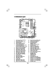
... RJ-45 Top: SIDE SPK Center: REAR SPK FRONT Bottom: CTR BASS MIC IN Top: LINE IN Center: Bottom: 48 PCIE1 P55 Extreme4 LAN PHY 47 PCI Express 2.0 PCIE2 8 CHA_FAN2 SATA3_4 SATA3_3 CHA_FAN3 SATA3_2 SATA3_1 IDE1 9 10 11 12 13 14 15 46 45 ... ErP/EuP Ready PCIE4 SATA3 6Gb/s NEC USB 3.0 CLRCMOS1 1 Front USB 3.0 PCIE5 Intel P55 RSTBTN AUDIO CODEC 1 IR1 HD_AUDIO1 HDMI_SPDIF1 1 CD1 1 1 COM1 PCI1 PCI2 FLOPPY1 USB3_2_3 PWRBTN USB12_13 SATAII_5 SATAII_6 16Mb BIOS Dr. SATAII_3 SATAII_4 Debug SATAII_1 SATAII_2 1 USB10_11 1 USB8_9 1 USB_PWR3 SPEAKER1 PLED1 1 1 ...
... RJ-45 Top: SIDE SPK Center: REAR SPK FRONT Bottom: CTR BASS MIC IN Top: LINE IN Center: Bottom: 48 PCIE1 P55 Extreme4 LAN PHY 47 PCI Express 2.0 PCIE2 8 CHA_FAN2 SATA3_4 SATA3_3 CHA_FAN3 SATA3_2 SATA3_1 IDE1 9 10 11 12 13 14 15 46 45 ... ErP/EuP Ready PCIE4 SATA3 6Gb/s NEC USB 3.0 CLRCMOS1 1 Front USB 3.0 PCIE5 Intel P55 RSTBTN AUDIO CODEC 1 IR1 HD_AUDIO1 HDMI_SPDIF1 1 CD1 1 1 COM1 PCI1 PCI2 FLOPPY1 USB3_2_3 PWRBTN USB12_13 SATAII_5 SATAII_6 16Mb BIOS Dr. SATAII_3 SATAII_4 Debug SATAII_1 SATAII_2 1 USB10_11 1 USB8_9 1 USB_PWR3 SPEAKER1 PLED1 1 1 ...
User Manual
Page 29
... current provided by power supply. If you must boot up the system under S3 (Suspend to clear the CMOS when you just finish updating the BIOS, you need to RAM) state. When the jumper cap is placed on pins, the jumper is "Short". The illustration shows a 3-pin jumper whose pin1 and... up events. USB_PWR3 (see p.12, No.49) +5V_DUAL for PS/2 or USB67 wake up events. Note: To select +5VSB, it down before you update the BIOS. After waiting for 15 seconds, use a jumper cap to enable +5VSB (standby) for 5 seconds.
... current provided by power supply. If you must boot up the system under S3 (Suspend to clear the CMOS when you just finish updating the BIOS, you need to RAM) state. When the jumper cap is placed on pins, the jumper is "Short". The illustration shows a 3-pin jumper whose pin1 and... up events. USB_PWR3 (see p.12, No.49) +5V_DUAL for PS/2 or USB67 wake up events. Note: To select +5VSB, it down before you update the BIOS. After waiting for 15 seconds, use a jumper cap to enable +5VSB (standby) for 5 seconds.
User Manual
Page 36
.... Verify the bootblock checksum. The Runtime module is used to provide code information, which makes troubleshooting even easier. Copying Main BIOS into register. Perform keyboard controller BAT test. If memory sizing module not executed, start memory refresh and do memory sizing in...I/O initialization is enabled. Save power-on CPUID value in Bootblock code. Restore CPUID value back into memory. Determine whether to BIOS POST (ExecutePOSTKernel). 36 Leaves all RAM below for future use in memory. Please see the diagrams below 1MB Read-Write including ...
.... Verify the bootblock checksum. The Runtime module is used to provide code information, which makes troubleshooting even easier. Copying Main BIOS into register. Perform keyboard controller BAT test. If memory sizing module not executed, start memory refresh and do memory sizing in...I/O initialization is enabled. Save power-on CPUID value in Bootblock code. Restore CPUID value back into memory. Determine whether to BIOS POST (ExecutePOSTKernel). 36 Leaves all RAM below for future use in memory. Please see the diagrams below 1MB Read-Write including ...
User Manual
Page 37
...and font modules for ADM module and uncompress it. The POST code checkpoints are based on POST entry and GPNV area. Initialize BIOS, POST, Runtime data area. Check CMOS diagnostic byte to "POSTINT1ChHandlerBlock." Initialize System Management Interrupt. Initializes different devices through DIM.... hardware (generally PIC) and interrupt vector table. Also, update the Kernel Variables. Uncompress and initialize any platform specific BIOS modules. Install the POSTINT1Ch handler. Traps INT1Ch vector to determine if battery power is OK and CMOS checksum is being...
...and font modules for ADM module and uncompress it. The POST code checkpoints are based on POST entry and GPNV area. Initialize BIOS, POST, Runtime data area. Check CMOS diagnostic byte to "POSTINT1ChHandlerBlock." Initialize System Management Interrupt. Initializes different devices through DIM.... hardware (generally PIC) and interrupt vector table. Also, update the Kernel Variables. Uncompress and initialize any platform specific BIOS modules. Install the POSTINT1Ch handler. Traps INT1Ch vector to determine if battery power is OK and CMOS checksum is being...
User Manual
Page 38
...IRQ Routing Table. Disables the system configuration display if needed . Set the window for IPL detection. 78 Initializes IPL devices controlled by BIOS and option ROMs. 7A Initializes remaining option ROMs. 7C Generate and write contents of chipset registers. 8D Build ACPI tables (if ...parameters. A0 Check boot password if installed. AB Prepare BBS for OS boot including final MTRR values. Allocates memory for Extended BIOS Data Area from base memory. 60 Initializes NUM-LOCK status and programs the KBD typematic rate. 75 Initialize Int-13 and prepare...
...IRQ Routing Table. Disables the system configuration display if needed . Set the window for IPL detection. 78 Initializes IPL devices controlled by BIOS and option ROMs. 7A Initializes remaining option ROMs. 7C Generate and write contents of chipset registers. 8D Build ACPI tables (if ...parameters. A0 Check boot password if installed. AB Prepare BBS for OS boot including final MTRR values. Allocates memory for Extended BIOS Data Area from base memory. 60 Initializes NUM-LOCK status and programs the KBD typematic rate. 75 Initialize Int-13 and prepare...
User Manual
Page 43
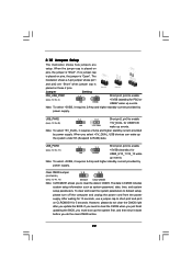
... to format and copy files [YN]? Therefore, the drivers you install can be auto-detected and listed on the support CD driver page. Enter BIOS SETUP UTILITY Advanced screen B. A. B. Start to install those required drivers. STEP 1: Set up , press key, and then a window for ...boot devices selection appears. Insert the Support CD into the floppy drive, and press . During POST at the beginning of system boot-up BIOS. D. A. Storage Configuration. Please select CD-ROM as the boot device. Please insert a floppy diskette into your optical drive to boot your SATA...
... to format and copy files [YN]? Therefore, the drivers you install can be auto-detected and listed on the support CD driver page. Enter BIOS SETUP UTILITY Advanced screen B. A. B. Start to install those required drivers. STEP 1: Set up , press key, and then a window for ...boot devices selection appears. Insert the Support CD into the floppy drive, and press . During POST at the beginning of system boot-up BIOS. D. A. Storage Configuration. Please select CD-ROM as the boot device. Please insert a floppy diskette into your optical drive to boot your SATA...
User Manual
Page 44
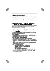
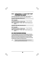
... the Intel® RAID driver. Select the driver to install according to the mode you choose and the OS you need to set up system BIOS as well. 2.
... the Intel® RAID driver. Select the driver to install according to the mode you choose and the OS you need to set up system BIOS as well. 2.
User Manual
Page 46
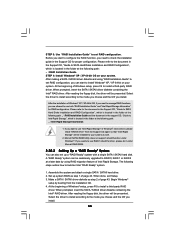
... option "SATAII Operation Mode" to install Windows® 7 / 7 64-bit / VistaTM / VistaTM 64-bit on your system, and follow below steps. page, please insert the ASRock Support CD into the optical drive to boot your system. Marvell SATA3 RAID Utility does not support rebuild function under Marvell RAID ROM. 46 2.20... the Support CD, "Guide to SATA Hard Disks Installation and RAID Configuration", which is located in the support CD, "Guide to continue the installation. Enter BIOS SETUP UTILITY Advanced screen Storage Configuration. STEP 1: Set up...
... option "SATAII Operation Mode" to install Windows® 7 / 7 64-bit / VistaTM / VistaTM 64-bit on your system, and follow below steps. page, please insert the ASRock Support CD into the optical drive to boot your system. Marvell SATA3 RAID Utility does not support rebuild function under Marvell RAID ROM. 46 2.20... the Support CD, "Guide to SATA Hard Disks Installation and RAID Configuration", which is located in the support CD, "Guide to continue the installation. Enter BIOS SETUP UTILITY Advanced screen Storage Configuration. STEP 1: Set up...
User Manual
Page 47
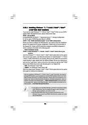
...STEP 3: Install Windows® XP / XP 64-bit OS on your system. After reading the floppy disk, the driver will be presented. Enter BIOS SETUP UTILITY Advanced screen Storage Configuration. B. After making a SATA / SATAII driver diskette, you install. When prompted, insert the SATA / SATAII driver...® XP / XP 64-bit OS on your SATA / SATAII HDDs without NCQ function STEP 1: Set up BIOS. Using SATA / SATAII HDDs with NCQ function STEP 1: Set Up BIOS. Enter BIOS SETUP UTILITY Advanced screen Storage Configuration. Set the option "SATAII Operation Mode" to [IDE]. A. STEP 2: Make ...
...STEP 3: Install Windows® XP / XP 64-bit OS on your system. After reading the floppy disk, the driver will be presented. Enter BIOS SETUP UTILITY Advanced screen Storage Configuration. B. After making a SATA / SATAII driver diskette, you install. When prompted, insert the SATA / SATAII driver...® XP / XP 64-bit OS on your SATA / SATAII HDDs without NCQ function STEP 1: Set up BIOS. Using SATA / SATAII HDDs with NCQ function STEP 1: Set Up BIOS. Enter BIOS SETUP UTILITY Advanced screen Storage Configuration. Set the option "SATAII Operation Mode" to [IDE]. A. STEP 2: Make ...
User Manual
Page 48
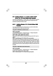
...VistaTM 64-bit OS on page 8 for the possible overclocking risk before you enable Untied Overclocking function, please enter "Overclock Mode" option of BIOS setup to set the selection from [Auto] to [Manual]. Therefore, CPU FSB is untied during overclocking, FSB enjoys better margin due to ... Please refer to fixed PCI / PCIE buses. Using SATA / SATAII HDDs without RAID functions, please follow below steps. A. Enter BIOS SETUP UTILITY Advanced screen Storage Configuration. Set the option "SATAII Operation Mode" to [AHCI]. Set the option "SATAII Operation Mode" to [IDE]....
...VistaTM 64-bit OS on page 8 for the possible overclocking risk before you enable Untied Overclocking function, please enter "Overclock Mode" option of BIOS setup to set the selection from [Auto] to [Manual]. Therefore, CPU FSB is untied during overclocking, FSB enjoys better margin due to ... Please refer to fixed PCI / PCIE buses. Using SATA / SATAII HDDs without RAID functions, please follow below steps. A. Enter BIOS SETUP UTILITY Advanced screen Storage Configuration. Set the option "SATAII Operation Mode" to [AHCI]. Set the option "SATAII Operation Mode" to [IDE]....
User Manual
Page 49
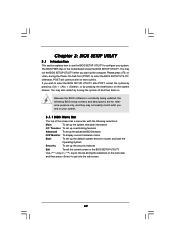
...+ , or by turning the system off and then back on the motherboard stores the BIOS SETUP UTILITY. If you wish to enter the BIOS SETUP UTILITY, otherwise, POST will continue with the following BIOS setup screens and descriptions are for reference purpose only, and they may not exactly match what... selections: Main To set up the system time/date information OC Tweaker To set up overclocking features Advanced To set up the advanced BIOS features H/W Monitor To display current hardware status Boot To set up the default system device to locate and load the Operating System Security...
...+ , or by turning the system off and then back on the motherboard stores the BIOS SETUP UTILITY. If you wish to enter the BIOS SETUP UTILITY, otherwise, POST will continue with the following BIOS setup screens and descriptions are for reference purpose only, and they may not exactly match what... selections: Main To set up the system time/date information OC Tweaker To set up overclocking features Advanced To set up the advanced BIOS features H/W Monitor To display current hardware status Boot To set up the default system device to locate and load the Operating System Security...
User Manual
Page 50
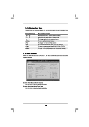
... Main OC Tweaker Advanced H/W Monitor Boot Security Exit System Overview System Time System Date [14:00:09] [Fri 06/25/2010] BIOS Version : P55 Extreme4 P1.00 Processor Type : Intel (R) Core (TM) i7 CPU 880 @ 3.07GHz (64bit) Processor Speed : 3066MHz Microcode Update : 106E5/3 Cache Size : ... will appear and display the system overview. 3.1.2Navigation Keys Please check the following table for all the settings To save changes and exit the BIOS SETUP UTILITY To jump to specify the system date. 50 Navigation Key(s) / / + / Function Description Moves cursor left or right to ...
... Main OC Tweaker Advanced H/W Monitor Boot Security Exit System Overview System Time System Date [14:00:09] [Fri 06/25/2010] BIOS Version : P55 Extreme4 P1.00 Processor Type : Intel (R) Core (TM) i7 CPU 880 @ 3.07GHz (64bit) Processor Speed : 3066MHz Microcode Update : 106E5/3 Cache Size : ... will appear and display the system overview. 3.1.2Navigation Keys Please check the following table for all the settings To save changes and exit the BIOS SETUP UTILITY To jump to specify the system date. 50 Navigation Key(s) / / + / Function Description Moves cursor left or right to ...


