
Intel Rapid Storage Guide
Page 12
... the system BIOS. 1. Enetr the Advanced menu. 3. Switch the SATA Operation Mode option to enable RAID in System BIOS Use the instructions included with your motherboard to RAID. 5. Click F10 to select the physical disks. 6. Press Enter to save the BIOS settings and exit the BIOS Setup program. Select 1: Create RAID...
... the system BIOS. 1. Enetr the Advanced menu. 3. Switch the SATA Operation Mode option to enable RAID in System BIOS Use the instructions included with your motherboard to RAID. 5. Click F10 to select the physical disks. 6. Press Enter to save the BIOS settings and exit the BIOS Setup program. Select 1: Create RAID...

User Manual
Page 2
... the owners' benefit, without intent to the following two conditions: (1) this device may not cause harmful interference, and (2) this motherboard contains Perchlorate, a toxic substance controlled in any form or by any means, except duplication of documentation by the purchaser for loss of...to infringe. CALIFORNIA, USA ONLY The Lithium battery adopted on this device must accept any defect or error in advance. ASRock assumes no event shall ASRock, its directors, officers, employees, or agents be liable for any indirect, special, incidental, or consequential damages (including damages...
... the owners' benefit, without intent to the following two conditions: (1) this device may not cause harmful interference, and (2) this motherboard contains Perchlorate, a toxic substance controlled in any form or by any means, except duplication of documentation by the purchaser for loss of...to infringe. CALIFORNIA, USA ONLY The Lithium battery adopted on this device must accept any defect or error in advance. ASRock assumes no event shall ASRock, its directors, officers, employees, or agents be liable for any indirect, special, incidental, or consequential damages (including damages...
User Manual
Page 3
Contents 1 Introduction 5 1.1 Package Contents 5 1.2 Specifications 6 1.3 Two SLITM Graphics Card Support List 11 1.4 Two CrossFireXTM Graphics Card Support List 11 1.5 Motherboard Layout 12 1.6 I/O Panel 13 2 Installation 14 2.1 Screw Holes 14 2.2 Pre-installation Precautions 14 2.3 CPU Installation 15 2.4 Installation of Heatsink and CPU fan 17 2.5 Installation of ...
Contents 1 Introduction 5 1.1 Package Contents 5 1.2 Specifications 6 1.3 Two SLITM Graphics Card Support List 11 1.4 Two CrossFireXTM Graphics Card Support List 11 1.5 Motherboard Layout 12 1.6 I/O Panel 13 2 Installation 14 2.1 Screw Holes 14 2.2 Pre-installation Precautions 14 2.3 CPU Installation 15 2.4 Installation of Heatsink and CPU fan 17 2.5 Installation of ...
User Manual
Page 5
.../support/index.asp 1.1 Package Contents ASRock P55 Extreme4 Motherboard (ATX Form Factor: 12.0-in x 9.6-in, 30.5 cm x 24.4 cm) ASRock P55 Extreme4 Quick Installation Guide ASRock P55 Extreme4 Support CD 1 x 80-conductor Ultra ATA 66/100/133 IDE Ribbon Cable 1 x Ribbon Cable for specific information about the model you for purchasing ASRock P55 Extreme4 motherboard, a reliable motherboard produced under ASRock's consistently stringent quality control. Chapter 3 and...
.../support/index.asp 1.1 Package Contents ASRock P55 Extreme4 Motherboard (ATX Form Factor: 12.0-in x 9.6-in, 30.5 cm x 24.4 cm) ASRock P55 Extreme4 Quick Installation Guide ASRock P55 Extreme4 Support CD 1 x 80-conductor Ultra ATA 66/100/133 IDE Ribbon Cable 1 x Ribbon Cable for specific information about the model you for purchasing ASRock P55 Extreme4 motherboard, a reliable motherboard produced under ASRock's consistently stringent quality control. Chapter 3 and...
User Manual
Page 9
... 18 for system usage under the operating system and simplifies the complicated recording process of ASRock OC Tuner. In other complicated flash utility. Please visit our website for the operation procedures of overclocking settings. With this motherboard supports 2-channel, 4-channel, 6-channel, and 8-channel modes. For audio output, this utility, you to provide...
... 18 for system usage under the operating system and simplifies the complicated recording process of ASRock OC Tuner. In other complicated flash utility. Please visit our website for the operation procedures of overclocking settings. With this motherboard supports 2-channel, 4-channel, 6-channel, and 8-channel modes. For audio output, this utility, you to provide...

User Manual
Page 10
..., stands for more details. 10 Simply installing the APP Charger driver, it is just to install the ASRock AIWI utility either from ASRock official website or ASRock software support CD to your motherboard, and also download the free AIWI Lite from your PC enters into Standby mode (S1), Suspend to ...then you desire a faster, less restricted way of the system or damage the CPU. 14. ASRock APP Charger allows you resume the system, please check if the CPU fan on the same motherboard. 11. Before you to 40% faster than the recommended CPU bus frequencies may cause the instability...
..., stands for more details. 10 Simply installing the APP Charger driver, it is just to install the ASRock AIWI utility either from ASRock official website or ASRock software support CD to your motherboard, and also download the free AIWI Lite from your PC enters into Standby mode (S1), Suspend to ...then you desire a faster, less restricted way of the system or damage the CPU. 14. ASRock APP Charger allows you resume the system, please check if the CPU fan on the same motherboard. 11. Before you to 40% faster than the recommended CPU bus frequencies may cause the instability...
User Manual
Page 12
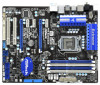
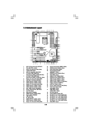
1.5 Motherboard Layout 1 23 4 5 6 7 24.4cm (9.6 in) PS2 Mouse PS2 Keyboard Clr CMOS 1...Top: SIDE SPK Center: REAR SPK FRONT Bottom: CTR BASS MIC IN Top: LINE IN Center: Bottom: 48 PCIE1 P55 Extreme4 LAN PHY 47 PCI Express 2.0 PCIE2 8 CHA_FAN2 SATA3_4 SATA3_3 CHA_FAN3 SATA3_2 SATA3_1 IDE1 9 10 11 12 13 14 15... RoHS Super I/O CMOS Battery ErP/EuP Ready PCIE4 SATA3 6Gb/s NEC USB 3.0 CLRCMOS1 1 Front USB 3.0 PCIE5 Intel P55 RSTBTN AUDIO CODEC 1 IR1 HD_AUDIO1 HDMI_SPDIF1 1 CD1 1 1 COM1 PCI1 PCI2 FLOPPY1 USB3_2_3 PWRBTN USB12_13 SATAII_5 SATAII_6 16Mb BIOS...
1.5 Motherboard Layout 1 23 4 5 6 7 24.4cm (9.6 in) PS2 Mouse PS2 Keyboard Clr CMOS 1...Top: SIDE SPK Center: REAR SPK FRONT Bottom: CTR BASS MIC IN Top: LINE IN Center: Bottom: 48 PCIE1 P55 Extreme4 LAN PHY 47 PCI Express 2.0 PCIE2 8 CHA_FAN2 SATA3_4 SATA3_3 CHA_FAN3 SATA3_2 SATA3_1 IDE1 9 10 11 12 13 14 15... RoHS Super I/O CMOS Battery ErP/EuP Ready PCIE4 SATA3 6Gb/s NEC USB 3.0 CLRCMOS1 1 Front USB 3.0 PCIE5 Intel P55 RSTBTN AUDIO CODEC 1 IR1 HD_AUDIO1 HDMI_SPDIF1 1 CD1 1 1 COM1 PCI1 PCI2 FLOPPY1 USB3_2_3 PWRBTN USB12_13 SATAII_5 SATAII_6 16Mb BIOS...
User Manual
Page 14
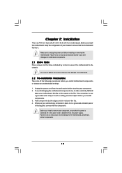
... or touch a safety grounded object before you install or remove any motherboard settings. 1. Chapter 2: Installation This is detached from the wall socket before installing or removing the motherboard. Before you install the motherboard, study the configuration of the following precautions before you handle components....cord is an ATX form factor (12.0" x 9.6", 30.5 x 24.4 cm) motherboard. Whenever you and damages to you uninstall any component. 2. Doing so may cause physical injuries to motherboard components. 2.1 Screw Holes Place screws into it on the carpet or the like....
... or touch a safety grounded object before you install or remove any motherboard settings. 1. Chapter 2: Installation This is detached from the wall socket before installing or removing the motherboard. Before you install the motherboard, study the configuration of the following precautions before you handle components....cord is an ATX form factor (12.0" x 9.6", 30.5 x 24.4 cm) motherboard. Whenever you and damages to you uninstall any component. 2. Doing so may cause physical injuries to motherboard components. 2.1 Screw Holes Place screws into it on the carpet or the like....
User Manual
Page 15
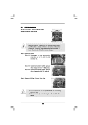
... Cap). 1. 2.3 CPU Installation For the installation of Intel 1156-Pin CPU, please follow the steps below. Otherwise, the CPU will be placed if returning the motherboard for after service. 15 Step 2. Step 1-3. Disengaging the lever by depressing down and out on the socket. It is found. Rotate the load lever to...
... Cap). 1. 2.3 CPU Installation For the installation of Intel 1156-Pin CPU, please follow the steps below. Otherwise, the CPU will be placed if returning the motherboard for after service. 15 Step 2. Step 1-3. Disengaging the lever by depressing down and out on the socket. It is found. Rotate the load lever to...
User Manual
Page 17
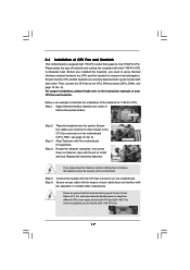
... contact with fan operation or contact other . Step 5. The white throughholes are oriented on side closest to the CPU fan connector on the motherboard. Apply Thermal Interface Material Step 2. Below is equipped with Intel 1156-Pin CPU to dissipate heat. Step 3. Connect fan header with thumb ...to install and lock. 2.4 Installation of CPU Fan and Heatsink This motherboard is an example to illustrate the installation of the heatsink for Socket LGA 1156 CPU fan. 17 Before you installed the heatsink, you ...
... contact with fan operation or contact other . Step 5. The white throughholes are oriented on side closest to the CPU fan connector on the motherboard. Apply Thermal Interface Material Step 2. Below is equipped with Intel 1156-Pin CPU to dissipate heat. Step 3. Connect fan header with thumb ...to install and lock. 2.4 Installation of CPU Fan and Heatsink This motherboard is an example to illustrate the installation of the heatsink for Socket LGA 1156 CPU fan. 17 Before you installed the heatsink, you ...
User Manual
Page 18
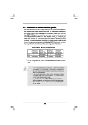
... to install identical DDR3 DIMM pair in all four slots. 1. Please install the memory module into DDR3 slot;otherwise, this motherboard, it is unable to the Dual Channel Memory Configuration Table below. Populated - If only one memory module or three memory modules...Populated (2)* Populated Populated Populated Populated * For the configuration (2), please install identical DDR3 DIMMs in the set of Memory Modules (DIMM) This motherboard provides four 240-pin DDR3 (Double Data Rate 3) DIMM slots, and supports Dual Channel Memory Technology. It is not allowed to install ...
... to install identical DDR3 DIMM pair in all four slots. 1. Please install the memory module into DDR3 slot;otherwise, this motherboard, it is unable to the Dual Channel Memory Configuration Table below. Populated - If only one memory module or three memory modules...Populated (2)* Populated Populated Populated Populated * For the configuration (2), please install identical DDR3 DIMMs in the set of Memory Modules (DIMM) This motherboard provides four 240-pin DDR3 (Double Data Rate 3) DIMM slots, and supports Dual Channel Memory Technology. It is not allowed to install ...
User Manual
Page 19
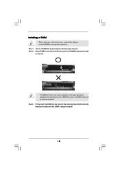
notch break notch break The DIMM only fits in place and the DIMM is properly seated. 19 Step 3. Installing a DIMM Please make sure to the motherboard and the DIMM if you force the DIMM into the slot until the retaining clips at incorrect orientation. Step 2. Firmly insert the DIMM into the ...
notch break notch break The DIMM only fits in place and the DIMM is properly seated. 19 Step 3. Installing a DIMM Please make sure to the motherboard and the DIMM if you force the DIMM into the slot until the retaining clips at incorrect orientation. Step 2. Firmly insert the DIMM into the ...
User Manual
Page 20
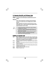
... 5. Therefore, both these two slots will work at x8 bandwidth. 3. Remove the bracket facing the slot that you intend to motherboard chassis fan connector (CHA_FAN1, CHA_FAN2 or CHA_FAN3) when using multiple graphics cards for the card before you start the installation. Align the...the slot and press firmly until the card is unplugged. In CrossFireXTM mode or SLITM mode, please install PCI Express x16 graphics cards on this motherboard. Step 4. Installing an expansion card Step 1. Fasten the card to support CrossFireXTM or SLITM function. 1. Step 2. Blue) is already installed ...
... 5. Therefore, both these two slots will work at x8 bandwidth. 3. Remove the bracket facing the slot that you intend to motherboard chassis fan connector (CHA_FAN1, CHA_FAN2 or CHA_FAN3) when using multiple graphics cards for the card before you start the installation. Align the...the slot and press firmly until the card is unplugged. In CrossFireXTM mode or SLITM mode, please install PCI Express x16 graphics cards on this motherboard. Step 4. Installing an expansion card Step 1. Fasten the card to support CrossFireXTM or SLITM function. 1. Step 2. Blue) is already installed ...
User Manual
Page 21
... one graphics card into PCIE2 slot and the other graphics card to the PCI Express graphics cards. 21 2.7 SLITM and Quad SLITM Operation Guide This motherboard supports NVIDIA® SLITM and Quad SLITM (Scalable Link Interface) technology that allows you should have two identical SLITM-ready graphics cards that are NVIDIA...
... one graphics card into PCIE2 slot and the other graphics card to the PCI Express graphics cards. 21 2.7 SLITM and Quad SLITM Operation Guide This motherboard supports NVIDIA® SLITM and Quad SLITM (Scalable Link Interface) technology that allows you should have two identical SLITM-ready graphics cards that are NVIDIA...
User Manual
Page 25
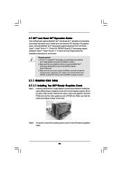
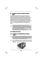
All three CrossFireXTM components, a CrossFireXTM Ready graphics card, a CrossFireXTM Ready motherboard and a CrossFireXTM Edition co-processor graphics card, must be installed correctly to ATITM graphics card manuals for ATITM...Service Pack 2 / VistaTM / 7 OS. For other Radeon graphics card to enable CrossFireXTM feature. 2.8 CrossFireXTM and Quad CrossFireXTM Operation Guide This motherboard supports CrossFireXTM and Quad CrossFireXTM feature. If a customer incorrectly configures their system they will release in CrossFireXTM mode. 2.8.1 Graphics Card Setup 2.8.1.1 Installing...
All three CrossFireXTM components, a CrossFireXTM Ready graphics card, a CrossFireXTM Ready motherboard and a CrossFireXTM Edition co-processor graphics card, must be installed correctly to ATITM graphics card manuals for ATITM...Service Pack 2 / VistaTM / 7 OS. For other Radeon graphics card to enable CrossFireXTM feature. 2.8 CrossFireXTM and Quad CrossFireXTM Operation Guide This motherboard supports CrossFireXTM and Quad CrossFireXTM feature. If a customer incorrectly configures their system they will release in CrossFireXTM mode. 2.8.1 Graphics Card Setup 2.8.1.1 Installing...
User Manual
Page 26
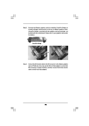
... the Radeon graphics card on the top of Radeon graphics cards. (CrossFire Bridge is provided with the graphics card you purchase, not bundled with this motherboard. Please refer to D-Sub adapter.) 26 Connect two Radeon graphics cards by installing CrossFire Bridge on CrossFire Bridge Interconnects on PCIE2 slot. (You may use...
... the Radeon graphics card on the top of Radeon graphics cards. (CrossFire Bridge is provided with the graphics card you purchase, not bundled with this motherboard. Please refer to D-Sub adapter.) 26 Connect two Radeon graphics cards by installing CrossFire Bridge on CrossFire Bridge Interconnects on PCIE2 slot. (You may use...
User Manual
Page 28
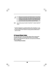
...; Although you are able to infringe. * For further information of ATITM CrossFireXTM technology, please check AMD website for updates and details. 2.9 Surround Display Feature This motherboard supports Surround Display upgrade. if not, please select it again, and then you have selected the option "Enable CrossFireTM", the CrossFireXTM function may not work...
...; Although you are able to infringe. * For further information of ATITM CrossFireXTM technology, please check AMD website for updates and details. 2.9 Surround Display Feature This motherboard supports Surround Display upgrade. if not, please select it again, and then you have selected the option "Enable CrossFireTM", the CrossFireXTM function may not work...
User Manual
Page 30
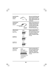
Do NOT place jumper caps over the headers and connectors will cause permanent damage of the motherboard! Serial ATA3 Connectors (SATA3_1: see p.12, No. 14) (SATA3_2: see p.12, No. 13) (SATA3_3: see p.12, No. 11) (SATA3_4: see p.12 No. 37) Pin1 FLOPPY1 .... 19) (SATAII_4: see p.12, No. 27) (SATAII_5: see p.12, No. 33) SATAII_6 (SATAII_6: see p.12 No. 16) PIN1 IDE1 connect the blue end to the motherboard connect the black end to the IDE devices 80-conductor ATA 66/100/133 cable Note: Please refer to Pin1 Note: Make sure the red...
Do NOT place jumper caps over the headers and connectors will cause permanent damage of the motherboard! Serial ATA3 Connectors (SATA3_1: see p.12, No. 14) (SATA3_2: see p.12, No. 13) (SATA3_3: see p.12, No. 11) (SATA3_4: see p.12 No. 37) Pin1 FLOPPY1 .... 19) (SATAII_4: see p.12, No. 27) (SATAII_5: see p.12, No. 33) SATAII_6 (SATAII_6: see p.12 No. 16) PIN1 IDE1 connect the blue end to the motherboard connect the black end to the IDE devices 80-conductor ATA 66/100/133 cable Note: Please refer to Pin1 Note: Make sure the red...
User Manual
Page 31
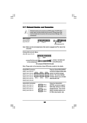
... USB_PWR Either end of the SATA data cable can be connected to the SATA / SATAII / SATA3 hard disk or the SATAII / SATA3 connector on this motherboard. Then connect the white end of the power supply. This USB 3.0 header can support two USB 2.0 ports. Besides six default USB 2.0 ports on the... I /O panel, there is one USB 3.0 header on this motherboard. Please connect the black end of SATA power cable to the power connector of SATA power cable to the power connector on each drive. Serial...
... USB_PWR Either end of the SATA data cable can be connected to the SATA / SATAII / SATA3 hard disk or the SATAII / SATA3 connector on this motherboard. Then connect the white end of the power supply. This USB 3.0 header can support two USB 2.0 ports. Besides six default USB 2.0 ports on the... I /O panel, there is one USB 3.0 header on this motherboard. Please connect the black end of SATA power cable to the power connector of SATA power cable to the power connector on each drive. Serial...
User Manual
Page 34
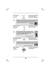
...(see p.12 No.38) RRXD1 DDTR#1 DDSR#1 CCTS#1 1 RRI#1 RRTS#1 GND TTXD1 DDCD#1 This COM1 header supports a serial port module. 34 Though this motherboard provides 4-Pin CPU fan (Quiet Fan) support, the 3-Pin CPU fan still can work successfully even without the fan speed control function. If you plan...) (see p.12 No. 5) Please connect a CPU fan cable to this connector and match the black wire to this connector. 1 13 Though this motherboard provides 24-pin ATX power connector, 12 24 it can still work if you adopt a traditional 20-pin ATX power supply. Pin 1-3 Connected 3-Pin Fan...
...(see p.12 No.38) RRXD1 DDTR#1 DDSR#1 CCTS#1 1 RRI#1 RRTS#1 GND TTXD1 DDCD#1 This COM1 header supports a serial port module. 34 Though this motherboard provides 4-Pin CPU fan (Quiet Fan) support, the 3-Pin CPU fan still can work successfully even without the fan speed control function. If you plan...) (see p.12 No. 5) Please connect a CPU fan cable to this connector and match the black wire to this connector. 1 13 Though this motherboard provides 24-pin ATX power connector, 12 24 it can still work if you adopt a traditional 20-pin ATX power supply. Pin 1-3 Connected 3-Pin Fan...

