User Manual
Page 4
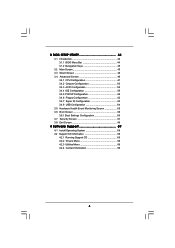
3 BIOS SETUP UTILITY 44 3.1 Introduction 44 3.1.1 BIOS Menu Bar 44 3.1.2 Navigation Keys 45 3.2 Main Screen 45 3.3 Smart Screen 46 3.4 Advanced Screen 46 3.4.1 CPU Configuration 47 3.4.2 Chipset Configuration 50 3.4.3 ACPI Configuration 58 3.4.4 IDE Configuration 59 3.4.5 PCIPnP Configuration 62 3.4.6 Floppy Configuration 62 3.4.7 Super IO Configuration 63 3.4.8 USB Configuration 64 3.5 Hardware Health Event Monitoring ...
3 BIOS SETUP UTILITY 44 3.1 Introduction 44 3.1.1 BIOS Menu Bar 44 3.1.2 Navigation Keys 45 3.2 Main Screen 45 3.3 Smart Screen 46 3.4 Advanced Screen 46 3.4.1 CPU Configuration 47 3.4.2 Chipset Configuration 50 3.4.3 ACPI Configuration 58 3.4.4 IDE Configuration 59 3.4.5 PCIPnP Configuration 62 3.4.6 Floppy Configuration 62 3.4.7 Super IO Configuration 63 3.4.8 USB Configuration 64 3.5 Hardware Health Event Monitoring ...
User Manual
Page 6
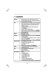
... Dual Core Wolfdale processors - Support DDR3 1600/1333/1066/800 non-ECC, un-buffered memory (see CAUTION 3) - Supports ATITM CrossFireXTM (see CAUTION 2) - 1.2 Specifications Platform CPU Chipset Memory Expansion Slot Audio LAN Rear Panel I /O Panel - 1 x PS/2 Mouse Port - 1 x PS/2 Keyboard Port - 1 x Coaxial SPDIF Out Port - 1 x Optical SPDIF Out Port - 1 x IEEE 1394 Port...
... Dual Core Wolfdale processors - Support DDR3 1600/1333/1066/800 non-ECC, un-buffered memory (see CAUTION 3) - Supports ATITM CrossFireXTM (see CAUTION 2) - 1.2 Specifications Platform CPU Chipset Memory Expansion Slot Audio LAN Rear Panel I /O Panel - 1 x PS/2 Mouse Port - 1 x PS/2 Keyboard Port - 1 x Coaxial SPDIF Out Port - 1 x Optical SPDIF Out Port - 1 x IEEE 1394 Port...
User Manual
Page 10
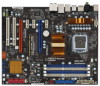
... SPK Center: REAR SPK FRONT Bottom: CTR BASS MIC IN Top: LINE IN Center: Bottom: PWR_FAN1 LAN PHY 1 CLRCMOS1 PCIE1 CMOS Battery Intel P45 Chipset Super I/O PCIE2 PCIE3 P45X3 Deluxe FSB2000 IDE1 VIA VT6330 FRONT_1394 1 IR1 1 AUDIO CODEC CD1 PCIE4 CrossFireX PCI Express 2.0 PCIE5 1394a PCI1 RoHS Debug LED 8Mb BIOS 1 HDMI_SPDIF1 1 HD_AUDIO1...
... SPK Center: REAR SPK FRONT Bottom: CTR BASS MIC IN Top: LINE IN Center: Bottom: PWR_FAN1 LAN PHY 1 CLRCMOS1 PCIE1 CMOS Battery Intel P45 Chipset Super I/O PCIE2 PCIE3 P45X3 Deluxe FSB2000 IDE1 VIA VT6330 FRONT_1394 1 IR1 1 AUDIO CODEC CD1 PCIE4 CrossFireX PCI Express 2.0 PCIE5 1394a PCI1 RoHS Debug LED 8Mb BIOS 1 HDMI_SPDIF1 1 HD_AUDIO1...
User Manual
Page 20
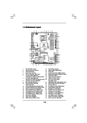
... card and a compatible standard Radeon (CrossFireXTM Ready) graphics card from ATITM or any 3D application. For Windows® XP Vendor Chipset Model Driver ATI Radeon HD 2600PRO MSI RX2600PRO-T2D256EZ Catalyst 9.1 Radeon HD 2600XT Gigabyte GV-RX26T256HP-B Catalyst 9.1 RADEON 3650 Powercolor AX3650... RADEON 4670 Powercolor AX4670 512MD3-P Catalyst 9.1 RADEON 4850 Gecube GC-HD485PG3-E3 Catalyst 9.1 For Windows® Vista Vendor Chipset ATI Radeon HD 2600PRO Radeon HD 2600XT RADEON 3650 RADEON 3850 RADEON 3870 RADEON 3870 Radeon HD 4350 RADEON 4670 RADEON 4850...
... card and a compatible standard Radeon (CrossFireXTM Ready) graphics card from ATITM or any 3D application. For Windows® XP Vendor Chipset Model Driver ATI Radeon HD 2600PRO MSI RX2600PRO-T2D256EZ Catalyst 9.1 Radeon HD 2600XT Gigabyte GV-RX26T256HP-B Catalyst 9.1 RADEON 3650 Powercolor AX3650... RADEON 4670 Powercolor AX4670 512MD3-P Catalyst 9.1 RADEON 4850 Gecube GC-HD485PG3-E3 Catalyst 9.1 For Windows® Vista Vendor Chipset ATI Radeon HD 2600PRO Radeon HD 2600XT RADEON 3650 RADEON 3850 RADEON 3870 RADEON 3870 Radeon HD 4350 RADEON 4670 RADEON 4850...
User Manual
Page 28
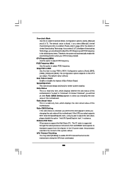
High Definition Audio supports Jack Sensing, but the panel wire on the lower right hand taskbar to function correctly. C. Enter Advanced Settings, and then select Chipset Configuration. Connect Mic_IN (MIC) to OUT2_L. B. D. Enter BIOS Setup Utility. F. Click the icon on the chassis must support HDA to enter Realtek HD Audio Manager. ...
High Definition Audio supports Jack Sensing, but the panel wire on the lower right hand taskbar to function correctly. C. Enter Advanced Settings, and then select Chipset Configuration. Connect Mic_IN (MIC) to OUT2_L. B. D. Enter BIOS Setup Utility. F. Click the icon on the chassis must support HDA to enter Realtek HD Audio Manager. ...
User Manual
Page 33
... CACHE. Early super I/O initialization is forced. Main BIOS checksum is used to it . Execute full memory sizing module. Do additional chipset initialization. Adjust policies and cache first 8MB. Set stack. BIOS now executes out of checkpoints that flat mode is done. CPUID information...sizing module not executed, start memory refresh and do memory sizing in PMM. Test base 512KB memory. Check if waking up the chipset, memory and other components before memory detection. Give control to checkpoint E0. Verify that flat mode is necessary, control flows to ...
... CACHE. Early super I/O initialization is forced. Main BIOS checksum is used to it . Execute full memory sizing module. Do additional chipset initialization. Adjust policies and cache first 8MB. Set stack. BIOS now executes out of checkpoints that flat mode is done. CPUID information...sizing module not executed, start memory refresh and do memory sizing in PMM. Test base 512KB memory. Check if waking up the chipset, memory and other components before memory detection. Give control to checkpoint E0. Verify that flat mode is necessary, control flows to ...
User Manual
Page 34
... set of checkpoints during the POST portion of document for ADM module and uncompress it. Initializes different devices. The following table describes the type of chipset registers. Initialize System Management Interrupt. Uncompress and initialize any platform specific BIOS modules. Give control to determine if battery power is OK and CMOS checksum...
... set of checkpoints during the POST portion of document for ADM module and uncompress it. Initializes different devices. The following table describes the type of chipset registers. Initialize System Management Interrupt. Uncompress and initialize any platform specific BIOS modules. Give control to determine if battery power is OK and CMOS checksum...
User Manual
Page 35
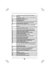
... POST INT1Ch vector and INT09h vector. Deinitializes the ADM module. A1 Clean-up work needed / requested. 8C Late POST initialization of chipset registers. 8D Build ACPI tables (if ACPI is supported) 8E Program the peripheral parameters. B1 Save system context for Int 19 boot...to the user and gets the user response for error. 87 Execute BIOS setup if needed before boot, which includes the programming of chipset registers. 40 Detect different devices (Parallel ports, serial ports, and coprocessor in CPU, etc.) successfully installed in the system. Prepares...
... POST INT1Ch vector and INT09h vector. Deinitializes the ADM module. A1 Clean-up work needed / requested. 8C Late POST initialization of chipset registers. 8D Build ACPI tables (if ACPI is supported) 8E Program the peripheral parameters. B1 Save system context for Int 19 boot...to the user and gets the user response for error. 87 Execute BIOS setup if needed before boot, which includes the programming of chipset registers. 40 Detect different devices (Parallel ports, serial ports, and coprocessor in CPU, etc.) successfully installed in the system. Prepares...
User Manual
Page 38
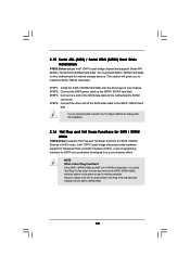
... 1: Install the SATA / SATAII hard disks into the SATA / SATAII HDD. 38 2.15 Serial ATA (SATA) / Serial ATAII (SATAII) Hard Disks Installation P45X3 Deluxe adopts Intel® ICH10 south bridge chipset that it is called "Hot Plug" for the action to the SATA / SATAII hard disk. You may install SATA / SATAII hard disks... the SATA data cable to switch the "Configure SATAII as" setting after OS installation. 2.16 Hot Plug and Hot Swap Functions for SATA / SATAII HDDs P45X3 Deluxe supports Hot Plug and Hot Swap functions for SATA host controllers developed thru a joint industry effort.
... 1: Install the SATA / SATAII hard disks into the SATA / SATAII HDD. 38 2.15 Serial ATA (SATA) / Serial ATAII (SATAII) Hard Disks Installation P45X3 Deluxe adopts Intel® ICH10 south bridge chipset that it is called "Hot Plug" for the action to the SATA / SATAII hard disk. You may install SATA / SATAII hard disks... the SATA data cable to switch the "Configure SATAII as" setting after OS installation. 2.16 Hot Plug and Hot Swap Functions for SATA / SATAII HDDs P45X3 Deluxe supports Hot Plug and Hot Swap functions for SATA host controllers developed thru a joint industry effort.
User Manual
Page 39
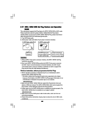
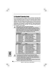
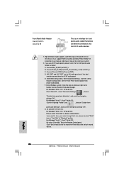
... Please make sure the SATA / SATAII driver is definitely not able to reduce the risk of our motherboard is available on our website: www.asrock.com 2. Make sure to power supply Caution 1. 2.17 SATA / SATAII HDD Hot Plug Feature and Operation Guide This motherboard supports Hot Plug feature...pack. Please read below operation guide of attention, before you process the SATA / SATAII HDD Hot Plug, please check below instructions step by the chipset because of its limitation, the SATA / SATAII Hot Plug support information of HDD crash or data loss. 39 SATA data cable (Red) B. ...
... Please make sure the SATA / SATAII driver is definitely not able to reduce the risk of our motherboard is available on our website: www.asrock.com 2. Make sure to power supply Caution 1. 2.17 SATA / SATAII HDD Hot Plug Feature and Operation Guide This motherboard supports Hot Plug feature...pack. Please read below operation guide of attention, before you process the SATA / SATAII HDD Hot Plug, please check below instructions step by the chipset because of its limitation, the SATA / SATAII Hot Plug support information of HDD crash or data loss. 39 SATA data cable (Red) B. ...
User Manual
Page 41
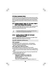
... format and copy files [YN]? Enter BIOS SETUP UTILITY Advanced screen IDE Configuration. C. WARNING! Since Windows® 2000 AHCI driver is not provided by the chipset vendor, AHCI function is not supported under Windows® 2000. 2.19.1 Installing Windows® 2000 / XP / XP 64-bit Without RAID Functions If you install...
... format and copy files [YN]? Enter BIOS SETUP UTILITY Advanced screen IDE Configuration. C. WARNING! Since Windows® 2000 AHCI driver is not provided by the chipset vendor, AHCI function is not supported under Windows® 2000. 2.19.1 Installing Windows® 2000 / XP / XP 64-bit Without RAID Functions If you install...

User Manual
Page 47
...Smart Advanced H/W Monitor Boot Security Exit Advanced Settings WARNING : Setting wrong values in this section, you execute ASRock Instant Flash utility, the utility will show the BIOS files and their respective information. Setting wrong values in ...below sections may cause system to malfunction. If you may set the configurations for the following items: CPU Configuration, Chipset Configuration, ACPI Configuration, IDE Configuration, PCIPnP Configuration, Floppy Configuration, SuperIO Configuration, and USB Configuration. Intel (R) C-STATE tech [Disabled...
...Smart Advanced H/W Monitor Boot Security Exit Advanced Settings WARNING : Setting wrong values in this section, you execute ASRock Instant Flash utility, the utility will show the BIOS files and their respective information. Setting wrong values in ...below sections may cause system to malfunction. If you may set the configurations for the following items: CPU Configuration, Chipset Configuration, ACPI Configuration, IDE Configuration, PCIPnP Configuration, Floppy Configuration, SuperIO Configuration, and USB Configuration. Intel (R) C-STATE tech [Disabled...
User Manual
Page 48
... Enable or disable the feature of the system caches. Ratio Actual Value This is "Locked" or "Unlocked". Please refer to keep the CPU from the chipset. Ratio Status This is a read-only item, which displays whether the ratio status of this motherboard is a read-only item, which displays the ratio actual...
... Enable or disable the feature of the system caches. Ratio Actual Value This is "Locked" or "Unlocked". Please refer to keep the CPU from the chipset. Ratio Status This is a read-only item, which displays whether the ratio status of this motherboard is a read-only item, which displays the ratio actual...

User Manual
Page 49
... want to enable this function, please set the "Power Schemes" as "Portable/Laptop" to [Enabled]. is set this item to the chipset power management hardware and flows. Migration of the power and thermal management flow into the processor allows us to use a hardware coordination mechanism in... Protection. No-Excute Memory Protection No-Execution (NX) Memory Protection Technology is determined and entered based on the lowest common denominator of the chipset as Microsoft® Windows® XP. This option will be hidden if the current CPU does not support Intel (R) SpeedStep(tm) tech...
... want to enable this function, please set the "Power Schemes" as "Portable/Laptop" to [Enabled]. is set this item to the chipset power management hardware and flows. Migration of the power and thermal management flow into the processor allows us to use a hardware coordination mechanism in... Protection. No-Excute Memory Protection No-Execution (NX) Memory Protection Technology is determined and entered based on the lowest common denominator of the chipset as Microsoft® Windows® XP. This option will be hidden if the current CPU does not support Intel (R) SpeedStep(tm) tech...
User Manual
Page 50
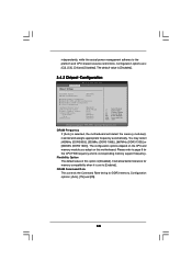
...is selected, the motherboard will allow better tolerance for memory compatibility when it is [Disabled]. 3.4.2 Chipset Configuration BIOS SETUP UTILITY Advanced Chipset Settings DRAM Frequency Flexibility Option DRAM Command Rate [Auto] [Disabled] [Auto] DRAM Timing Configuration ...DRAM RCOMP and tRD Configuration DRAM DLL SKEW Configuration Voltage Configuration Intelligent Energy Saver ASRock VDrop Control Primary Graphics Adapter...
...is selected, the motherboard will allow better tolerance for memory compatibility when it is [Disabled]. 3.4.2 Chipset Configuration BIOS SETUP UTILITY Advanced Chipset Settings DRAM Frequency Flexibility Option DRAM Command Rate [Auto] [Disabled] [Auto] DRAM Timing Configuration ...DRAM RCOMP and tRD Configuration DRAM DLL SKEW Configuration Voltage Configuration Intelligent Energy Saver ASRock VDrop Control Primary Graphics Adapter...
User Manual
Page 63
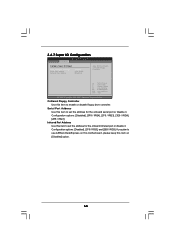
....54 (C) Copyright 1985-2005, American Megatrends, Inc. 3.4.7 Super IO Configuration BIOS SETUP UTILITY Advanced Configure Super IO Chipset OnBoard Floppy Controller Serial Port Address Infrared Port Address [Enabled] [3F8 / IRQ4] [Disabled] Allow BIOS to use ASRock DeskExpress on this motherboard, please keep this item on [Disabled] option. 63 Configuration options: [Disabled], [3F8...
....54 (C) Copyright 1985-2005, American Megatrends, Inc. 3.4.7 Super IO Configuration BIOS SETUP UTILITY Advanced Configure Super IO Chipset OnBoard Floppy Controller Serial Port Address Infrared Port Address [Enabled] [3F8 / IRQ4] [Disabled] Allow BIOS to use ASRock DeskExpress on this motherboard, please keep this item on [Disabled] option. 63 Configuration options: [Disabled], [3F8...
Quick Installation Guide
Page 5
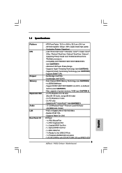
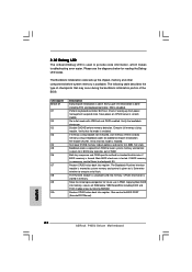
... DDR3 1600/1333/1066/800 non-ECC, un-buffered memory (see CAUTION 2) - PCIE x1 Gigabit LAN 10/100/1000 Mb/s - 1.2 Specifications Platform CPU Chipset Memory Expansion Slot Audio LAN Rear Panel I /O Panel - 1 x PS/2 Mouse Port - 1 x PS/2 Keyboard Port - 1 x Coaxial SPDIF Out...-quality Conductive Polymer Capacitors) - Supports Hyper-Threading Technology (see CAUTION 5) - Compatible with LED (ACT/LINK LED and SPEED LED) 5 ASRock P45X3 Deluxe Motherboard English Advanced V8 Power Phase Design - Southbridge: Intel® ICH10 - LGA 775 for Intel® CoreTM 2 Extreme / CoreTM ...
... DDR3 1600/1333/1066/800 non-ECC, un-buffered memory (see CAUTION 2) - PCIE x1 Gigabit LAN 10/100/1000 Mb/s - 1.2 Specifications Platform CPU Chipset Memory Expansion Slot Audio LAN Rear Panel I /O Panel - 1 x PS/2 Mouse Port - 1 x PS/2 Keyboard Port - 1 x Coaxial SPDIF Out...-quality Conductive Polymer Capacitors) - Supports Hyper-Threading Technology (see CAUTION 5) - Compatible with LED (ACT/LINK LED and SPEED LED) 5 ASRock P45X3 Deluxe Motherboard English Advanced V8 Power Phase Design - Southbridge: Intel® ICH10 - LGA 775 for Intel® CoreTM 2 Extreme / CoreTM ...
Quick Installation Guide
Page 16
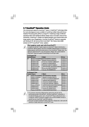
...incorrectly configures their system they will operate as 12-pipe cards while in a single PC. For Windows® XP Vendor Chipset Model Driver ATI Radeon HD 2600PRO MSI RX2600PRO-T2D256EZ Catalyst 9.1 Radeon HD 2600XT Gigabyte GV-RX26T256HP-B Catalyst 9.1 RADEON 3650 ...of performance and image quality in any of combining multiple high performance Graphics Processing Units (GPU) in CrossFireXTM mode. 16 ASRock P45X3 Deluxe Motherboard All three CrossFireXTM components, a CrossFireXTM Ready graphics card, a CrossFireXTM Ready motherboard and a CrossFireXTM Edition co-processor...
...incorrectly configures their system they will operate as 12-pipe cards while in a single PC. For Windows® XP Vendor Chipset Model Driver ATI Radeon HD 2600PRO MSI RX2600PRO-T2D256EZ Catalyst 9.1 Radeon HD 2600XT Gigabyte GV-RX26T256HP-B Catalyst 9.1 RADEON 3650 ...of performance and image quality in any of combining multiple high performance Graphics Processing Units (GPU) in CrossFireXTM mode. 16 ASRock P45X3 Deluxe Motherboard All three CrossFireXTM components, a CrossFireXTM Ready graphics card, a CrossFireXTM Ready motherboard and a CrossFireXTM Edition co-processor...
Quick Installation Guide
Page 24
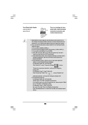
...: Click the right-top "Folder" icon , choose "Disable front panel jack detection", and save the change by clicking "OK". Enter Advanced Settings, and then select Chipset Configuration. Click "Set Default Device" to the front panel audio header as below: A. English 24 ASRock P45X3 Deluxe Motherboard If you want to function correctly.
...: Click the right-top "Folder" icon , choose "Disable front panel jack detection", and save the change by clicking "OK". Enter Advanced Settings, and then select Chipset Configuration. Click "Set Default Device" to the front panel audio header as below: A. English 24 ASRock P45X3 Deluxe Motherboard If you want to function correctly.
Quick Installation Guide
Page 28
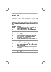
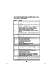
... now executes out of the BIOS: Checkpoint Before D1 D1 D0 D2 D3 D4 D5 D6 D7 D8 D9 DA Description Early chipset initialization is uncompressed into memory. If BIOS recovery is given to determine if BIOS recovery is tested. Set stack. Bootblock code is...memory sizing module. Do additional chipset initialization. CPUID information is used to execute serial flash. Please see the diagrams below 1MB Read-Write including E000 and F000 shadow areas but closing SMRAM. Adjust policies and cache first 8MB. English 28 ASRock P45X3 Deluxe Motherboard The Bootblock initialization code ...
... now executes out of the BIOS: Checkpoint Before D1 D1 D0 D2 D3 D4 D5 D6 D7 D8 D9 DA Description Early chipset initialization is uncompressed into memory. If BIOS recovery is given to determine if BIOS recovery is tested. Set stack. Bootblock code is...memory sizing module. Do additional chipset initialization. CPUID information is used to execute serial flash. Please see the diagrams below 1MB Read-Write including E000 and F000 shadow areas but closing SMRAM. Adjust policies and cache first 8MB. English 28 ASRock P45X3 Deluxe Motherboard The Bootblock initialization code ...

