
User Manual
Page 6
.../s - Giga PHY Realtek RTL8211B - FSB 2600 MHz (5.2 GT/s) (see CAUTION 4) - K10N78hSLI-1394 - 7.1 CH Windows® VistaTM Premium Level HD Audio (ALC888 Audio Codec) LAN -...Port 6 AMD LIVE!TM Ready - Max. Supports NVIDIA® Hybrid SLITM GeForce® Boost feature (see CAUTION 3) - 4 x DDR2 DIMM slots - Supports Wake-On-LAN Wireless LAN - Dual Channel DDR2 Memory Technology (see CAUTION 6) Audio - 1.2 Specifications Platform - All Solid Capacitor design CPU - Supports AMD's Cool 'n' QuietTM Technology - ASRock WiFi-802.11g module (K10N78hSLI...
.../s - Giga PHY Realtek RTL8211B - FSB 2600 MHz (5.2 GT/s) (see CAUTION 4) - K10N78hSLI-1394 - 7.1 CH Windows® VistaTM Premium Level HD Audio (ALC888 Audio Codec) LAN -...Port 6 AMD LIVE!TM Ready - Max. Supports NVIDIA® Hybrid SLITM GeForce® Boost feature (see CAUTION 3) - 4 x DDR2 DIMM slots - Supports Wake-On-LAN Wireless LAN - Dual Channel DDR2 Memory Technology (see CAUTION 6) Audio - 1.2 Specifications Platform - All Solid Capacitor design CPU - Supports AMD's Cool 'n' QuietTM Technology - ASRock WiFi-802.11g module (K10N78hSLI...

User Manual
Page 7
... 1, RAID 0+1, JBOD and RAID 5), NCQ, AHCI and "Hot Plug" functions (see CAUTION 8) - 1 x eSATAII 3.0Gb/s connector (shared with LED (ACT/LINK LED and SPEED LED) - 1 x IEEE 1394 Port - ASRock OC Tuner (see CAUTION 13) - Supports jumperfree - HD Audio Jack: Side Speaker/Rear Speaker/Central/Bass/ Line in header - AMBIOS 2.3.1 Support - Intelligent Energy Saver (see...
... 1, RAID 0+1, JBOD and RAID 5), NCQ, AHCI and "Hot Plug" functions (see CAUTION 8) - 1 x eSATAII 3.0Gb/s connector (shared with LED (ACT/LINK LED and SPEED LED) - 1 x IEEE 1394 Port - ASRock OC Tuner (see CAUTION 13) - Supports jumperfree - HD Audio Jack: Side Speaker/Rear Speaker/Central/Bass/ Line in header - AMBIOS 2.3.1 Support - Intelligent Energy Saver (see...

User Manual
Page 11
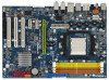
1.4 Motherboard Layout (K10N78hSLI-WiFi) 12 1 PS2_USB_PW1 3 45 21.3cm (8.4-in) 67 PS2 Mouse PS2 Keyboard DDR2 1066 eSATAII_TOP Coaxial Optical SPDIF SPDIF 36 35 ATX12V1 1 COM1 USB 2.0 T: USB4 B: USB5 Bottom: ESATAII USB 2.0 Top: T: USB2 IEEE B: USB3 1394 USB 2.0 T: USB0 B: USB1 Top: RJ-45 SOCKET ...33 PCI Express x16 Slot (PCIE1, Green) 16 SATAII Connector (SATAII_1 (PORT0)) 34 ATX Power Connector (ATXPWR1) 17 SPI BIOS Chip 35 COM Port Header (COM1) 18 SATAII Connector (SATAII_3 (PORT2)) 36 eSATAII Connector (eSATAII_TOP) 11 Yellow) (IR1) 7 2 x 240-pin DDR2 DIMM Slots ...
1.4 Motherboard Layout (K10N78hSLI-WiFi) 12 1 PS2_USB_PW1 3 45 21.3cm (8.4-in) 67 PS2 Mouse PS2 Keyboard DDR2 1066 eSATAII_TOP Coaxial Optical SPDIF SPDIF 36 35 ATX12V1 1 COM1 USB 2.0 T: USB4 B: USB5 Bottom: ESATAII USB 2.0 Top: T: USB2 IEEE B: USB3 1394 USB 2.0 T: USB0 B: USB1 Top: RJ-45 SOCKET ...33 PCI Express x16 Slot (PCIE1, Green) 16 SATAII Connector (SATAII_1 (PORT0)) 34 ATX Power Connector (ATXPWR1) 17 SPI BIOS Chip 35 COM Port Header (COM1) 18 SATAII Connector (SATAII_3 (PORT2)) 36 eSATAII Connector (eSATAII_TOP) 11 Yellow) (IR1) 7 2 x 240-pin DDR2 DIMM Slots ...

User Manual
Page 12
... Connector (SATAII_1 (PORT0)) 34 ATX Power Connector (ATXPWR1) 17 SPI BIOS Chip 35 COM Port Header (COM1) 18 SATAII Connector (SATAII_3 (PORT2)) 36 eSATAII Connector (eSATAII_TOP) 12 1.5 Motherboard Layout (K10N78hSLI-1394) 12 1 PS2_USB_PW1 3 45 21.3cm (8.4-in) 67 PS2 Mouse PS2 Keyboard DDR2 1066 ...IN Center: FRONT Bottom: MIC IN 34 33 32 31 30 29 28 27 CPU_FAN1 Dual Channel AM2+ LAN PHY PCIE1 PCI Express 2.0 K10N78hSLI-1394 PCIE2 CLRCMOS1 1 CMOS BATTERY Super I/O PCIE3 FRONT_1394 1 HDMI_SPDIF1 1 AUDIO CODEC 1 WIFI/E HD_AUDIO1 CD1 1 IR1 1 FLOPPY1 PCI1 RoHS PCI2...
... Connector (SATAII_1 (PORT0)) 34 ATX Power Connector (ATXPWR1) 17 SPI BIOS Chip 35 COM Port Header (COM1) 18 SATAII Connector (SATAII_3 (PORT2)) 36 eSATAII Connector (eSATAII_TOP) 12 1.5 Motherboard Layout (K10N78hSLI-1394) 12 1 PS2_USB_PW1 3 45 21.3cm (8.4-in) 67 PS2 Mouse PS2 Keyboard DDR2 1066 ...IN Center: FRONT Bottom: MIC IN 34 33 32 31 30 29 28 27 CPU_FAN1 Dual Channel AM2+ LAN PHY PCIE1 PCI Express 2.0 K10N78hSLI-1394 PCIE2 CLRCMOS1 1 CMOS BATTERY Super I/O PCIE3 FRONT_1394 1 HDMI_SPDIF1 1 AUDIO CODEC 1 WIFI/E HD_AUDIO1 CD1 1 IR1 1 FLOPPY1 PCI1 RoHS PCI2...

User Manual
Page 13
... computer, you use 2-channel speaker, please connect the speaker's plug into "Front Speaker Jack". After restarting your system. 1.6 ASRock 1394_SPDIF I/O 1 2 3 4 7 5 8 6 9 16 15 14 13 12 11 10 1 PS/2 Mouse Port (Green) 2 IEEE 1394 Port * 3 LAN RJ-45 Port 4 Side Speaker (Gray) 5 Rear Speaker (Black) 6 Central / Bass (Orange) 7 Line In (Light Blue) **8 Front Speaker (Lime) 9 Microphone...
... computer, you use 2-channel speaker, please connect the speaker's plug into "Front Speaker Jack". After restarting your system. 1.6 ASRock 1394_SPDIF I/O 1 2 3 4 7 5 8 6 9 16 15 14 13 12 11 10 1 PS/2 Mouse Port (Green) 2 IEEE 1394 Port * 3 LAN RJ-45 Port 4 Side Speaker (Gray) 5 Rear Speaker (Black) 6 Central / Bass (Orange) 7 Line In (Light Blue) **8 Front Speaker (Lime) 9 Microphone...

User Manual
Page 24
This header supports WiFi+AP function with ASRock WiFi-802.11g or WiFi-802.11n module, an easy-to-use the SATA data cable to connect SATAII_6 (PORT5) connector and eSATAII connector. Either ... ATA (SATA) Power Cable (Optional) connect to the SATA HDD power connector connect to 3.0 Gb/s data transfer rate. You can support two USB 2.0 ports. Besides six default USB 2.0 ports on the I/O panel, there are two USB 2.0 headers on this motherboard. Please connect the black end of wireless network connectivity. It allows you...
This header supports WiFi+AP function with ASRock WiFi-802.11g or WiFi-802.11n module, an easy-to-use the SATA data cable to connect SATAII_6 (PORT5) connector and eSATAII connector. Either ... ATA (SATA) Power Cable (Optional) connect to the SATA HDD power connector connect to 3.0 Gb/s data transfer rate. You can support two USB 2.0 ports. Besides six default USB 2.0 ports on the I/O panel, there are two USB 2.0 headers on this motherboard. Please connect the black end of wireless network connectivity. It allows you...

User Manual
Page 25
... manual and chassis manual to OUT2_L. B. Connect Audio_R (RIN) to OUT2_R and Audio_L (LIN) to install your system. 2. You don't need to connect them for ASRock DeskExpress. Enter Advanced Settings, and then select Chipset Configuration. If you use WiFi+AP functin on the chassis must support HDA to Ground (GND). Enter... don't plan to use AC'97 audio panel, please install it to the front panel audio header as a 4-Pin USB 2.0 header to support one USB 2.0 port.
... manual and chassis manual to OUT2_L. B. Connect Audio_R (RIN) to OUT2_R and Audio_L (LIN) to install your system. 2. You don't need to connect them for ASRock DeskExpress. Enter Advanced Settings, and then select Chipset Configuration. If you use WiFi+AP functin on the chassis must support HDA to Ground (GND). Enter... don't plan to use AC'97 audio panel, please install it to the front panel audio header as a 4-Pin USB 2.0 header to support one USB 2.0 port.

User Manual
Page 27
... and Pin 5. 5 1 4-Pin ATX 12V Power Supply Installation 8 4 IEEE 1394 Header (9-pin FRONT_1394) (see p.11/12 No. 30) Serial port Header (9-pin COM1) (see p.11/12, No. 2) 5 1 8 4 Please note that it is one IEEE 1394 port. To use the 20-pin ATX power supply, please plug your power supply along... RXTPBM_0 +12V GND 1 +12V RXTPBP_0 GND RXTPAP_0 RRXD1 DDTR#1 DDSR#1 CCTS#1 1 RRI#1 RRTS#1 GND TTXD1 DDCD#1 Besides one default IEEE 1394 port on this motherboard. To use the 4-pin ATX power supply, please plug your power supply along with ATX 12V plug to this connector. This ...
... and Pin 5. 5 1 4-Pin ATX 12V Power Supply Installation 8 4 IEEE 1394 Header (9-pin FRONT_1394) (see p.11/12 No. 30) Serial port Header (9-pin COM1) (see p.11/12, No. 2) 5 1 8 4 Please note that it is one IEEE 1394 port. To use the 20-pin ATX power supply, please plug your power supply along... RXTPBM_0 +12V GND 1 +12V RXTPBP_0 GND RXTPAP_0 RRXD1 DDTR#1 DDSR#1 CCTS#1 1 RRI#1 RRTS#1 GND TTXD1 DDCD#1 Besides one default IEEE 1394 port on this motherboard. To use the 4-pin ATX power supply, please plug your power supply along with ATX 12V plug to this connector. This ...
User Manual
Page 30
... up to 3000Mb/s, which is much higher than USB 2.0 and IEEE 1394, and still keeps the convenience of Hot Plug feature. Therefore, you can insert or remove your eSATAII devices to the eSATAII ports while the system is supported with eSATAII interface, you want to add the eSATAII HDD as a ...enables you set "SATA Operation Mode" option in the near future, eSATAII will replace USB 2.0 and IEEE 1394 to RAID mode. otherwise, it may simply plug your eSATAII hard disk to the eSATAII ports instead of opening your SATAII hard disk. Please refer to page 38 to 3.0Gb/s, and the convenient ...
... up to 3000Mb/s, which is much higher than USB 2.0 and IEEE 1394, and still keeps the convenience of Hot Plug feature. Therefore, you can insert or remove your eSATAII devices to the eSATAII ports while the system is supported with eSATAII interface, you want to add the eSATAII HDD as a ...enables you set "SATA Operation Mode" option in the near future, eSATAII will replace USB 2.0 and IEEE 1394 to RAID mode. otherwise, it may simply plug your eSATAII hard disk to the eSATAII ports instead of opening your SATAII hard disk. Please refer to page 38 to 3.0Gb/s, and the convenient ...

User Manual
Page 31
Connect one end of the eSATAII device cable to eSATAII device Connect the other end of the eSATAII device cable to eSATAII port of the I /O shield, you connect the SATA data cable. see p.11/12 No.11) and the eSATAII connector (eSATAII_TOP; SATAII_6 (PORT5) eSATAII_TOP 1. see... p.11/12 No.36) with a SATA data cable first. In order to enable the eSATAII port of the I/O shield according to connect eSATAII device and the eSATAII port of the I /O shield 31 How to the eSATAII connector (eSATAII_TOP) 2. Use the eSATAII device cable to the eSATAII ...
Connect one end of the eSATAII device cable to eSATAII device Connect the other end of the eSATAII device cable to eSATAII port of the I /O shield, you connect the SATA data cable. see p.11/12 No.11) and the eSATAII connector (eSATAII_TOP; SATAII_6 (PORT5) eSATAII_TOP 1. see... p.11/12 No.36) with a SATA data cable first. In order to enable the eSATAII port of the I/O shield according to connect eSATAII device and the eSATAII port of the I /O shield 31 How to the eSATAII connector (eSATAII_TOP) 2. Use the eSATAII device cable to the eSATAII ...

User Manual
Page 34
..., you need to the SATA / SATAII hard disk. 1. You may install SATA / SATAII hard disks on other SATAII ports. 3. STEP 2: Connect the SATA power cable to build RAID on internal SATAII ports. In other end of the SATA data cable to install 4 SATA / SATAII hard disks. 2. If you plan to ...use RAID 0, RAID 1 or JBOD function, you to the motherboard's SATAII connector. It is used for eSATAII port, please build RAID on this motherboard for internal storage devices. STEP 1: Install the SATA / SATAII hard disks into the drive bays of the SATA data...
..., you need to the SATA / SATAII hard disk. 1. You may install SATA / SATAII hard disks on other SATAII ports. 3. STEP 2: Connect the SATA power cable to build RAID on internal SATAII ports. In other end of the SATA data cable to install 4 SATA / SATAII hard disks. 2. If you plan to ...use RAID 0, RAID 1 or JBOD function, you to the motherboard's SATAII connector. It is used for eSATAII port, please build RAID on this motherboard for internal storage devices. STEP 1: Install the SATA / SATAII hard disks into the drive bays of the SATA data...

User Manual
Page 35
... the OS has been installed into the SATA / SATAII HDD. However, please note that enables you may simply plug your eSATAII devices to the eSATAII ports instead of opening your chassis to exchange your SATAII hard disk. 35 If SATA / SATAII HDDs are NOT set for RAID configuration, it is called...
... the OS has been installed into the SATA / SATAII HDD. However, please note that enables you may simply plug your eSATAII devices to the eSATAII ports instead of opening your chassis to exchange your SATAII hard disk. 35 If SATA / SATAII HDDs are NOT set for RAID configuration, it is called...
User Manual
Page 40
...CD: .. \ RAID Installation Guide 40 STEP 1: Set Up BIOS. Before you start to configure RAID function, you want to enable Hot Plug function on eSATAII ports but you install OS on your SATA / SATAII HDDs with RAID functions, please follow step 1 to set RAID configuration. STEP 3: Set Up BIOS. Using SATA... / SATAII HDDs and eSATAII devices without NCQ and Hot Plug functions STEP 1: Set Up BIOS. A. Enter BIOS SETUP UTILITY Advanced screen B. (There are two ASRock Support CD in the motherboard gift box pack, please choose the one for proper configuration.
...CD: .. \ RAID Installation Guide 40 STEP 1: Set Up BIOS. Before you start to configure RAID function, you want to enable Hot Plug function on eSATAII ports but you install OS on your SATA / SATAII HDDs with RAID functions, please follow step 1 to set RAID configuration. STEP 3: Set Up BIOS. Using SATA... / SATAII HDDs and eSATAII devices without NCQ and Hot Plug functions STEP 1: Set Up BIOS. A. Enter BIOS SETUP UTILITY Advanced screen B. (There are two ASRock Support CD in the motherboard gift box pack, please choose the one for proper configuration.

User Manual
Page 54
... OS on SATA / SATAII HDDs, please do not change the setting of this option to [Enabled] if you want to operate RAID function on eSATAII port and plan to make a floppy image or use this option to [non-RAID]. ACPI HPET Table Use this item to enable or disable the "OnBoard...
... OS on SATA / SATAII HDDs, please do not change the setting of this option to [Enabled] if you want to operate RAID function on eSATAII port and plan to make a floppy image or use this option to [non-RAID]. ACPI HPET Table Use this item to enable or disable the "OnBoard...

User Manual
Page 57
... Megatrends, Inc. Configuration options: [Disabled], [3F8 / IRQ4], [2F8 / IRQ3], [3E8 / IRQ4], [2E8 / IRQ3]. Serial Port Address Use this item to use ASRock DeskExpress on this motherboard, please keep this item on [Disabled] option. 57 3.3.6Floppy Configuration In this section, you plan to set the... address for the onboard serial port or disable it . BIOS SETUP UTILITY Advanced Floppy Configuration Floppy ...
... Megatrends, Inc. Configuration options: [Disabled], [3F8 / IRQ4], [2F8 / IRQ3], [3E8 / IRQ4], [2E8 / IRQ3]. Serial Port Address Use this item to use ASRock DeskExpress on this motherboard, please keep this item on [Disabled] option. 57 3.3.6Floppy Configuration In this section, you plan to set the... address for the onboard serial port or disable it . BIOS SETUP UTILITY Advanced Floppy Configuration Floppy ...

Quick Installation Guide
Page 2
... 3) 10 SATAII Connector (SATAII_5 (PORT4)) 29 HDMI_SPDIF Header (HDMI_SPDIF1) 11 SATAII Connector (SATAII_6 (PORT5)) 30 Front Panel IEEE 1394 Header 12 SATAII Connector (SATAII_4 (PORT3)) (FRONT_1394) 13 SATAII Connector (SATAII_2 (PORT1)) 31 PCI Express x1 Slot (PCIE3, ...34 ATX Power Connector (ATXPWR1) 17 SPI BIOS Chip 35 COM Port Header (COM1) 18 SATAII Connector (SATAII_3 (PORT2)) 36 eSATAII Connector (eSATAII_TOP) 2 ASRock K10N78hSLI-WiFi / K10N78hSLI-1394 Motherboard Motherboard Layout (K10N78hSLI-WiFi) English 1 PS2_USB_PW1 Jumper 19 NVIDIA GeForce 8200 Chipset 2 ATX...
... 3) 10 SATAII Connector (SATAII_5 (PORT4)) 29 HDMI_SPDIF Header (HDMI_SPDIF1) 11 SATAII Connector (SATAII_6 (PORT5)) 30 Front Panel IEEE 1394 Header 12 SATAII Connector (SATAII_4 (PORT3)) (FRONT_1394) 13 SATAII Connector (SATAII_2 (PORT1)) 31 PCI Express x1 Slot (PCIE3, ...34 ATX Power Connector (ATXPWR1) 17 SPI BIOS Chip 35 COM Port Header (COM1) 18 SATAII Connector (SATAII_3 (PORT2)) 36 eSATAII Connector (eSATAII_TOP) 2 ASRock K10N78hSLI-WiFi / K10N78hSLI-1394 Motherboard Motherboard Layout (K10N78hSLI-WiFi) English 1 PS2_USB_PW1 Jumper 19 NVIDIA GeForce 8200 Chipset 2 ATX...

Quick Installation Guide
Page 3
Motherboard Layout (K10N78hSLI-1394) English 1 PS2_USB_PW1 Jumper 19 NVIDIA GeForce 8200 Chipset 2 ATX 12V ...3) 10 SATAII Connector (SATAII_5 (PORT4)) 29 HDMI_SPDIF Header (HDMI_SPDIF1) 11 SATAII Connector (SATAII_6 (PORT5)) 30 Front Panel IEEE 1394 Header 12 SATAII Connector (SATAII_4 (PORT3)) (FRONT_1394) 13 SATAII Connector (SATAII_2 (PORT1)) 31 PCI Express x1 Slot (PCIE3,...34 ATX Power Connector (ATXPWR1) 17 SPI BIOS Chip 35 COM Port Header (COM1) 18 SATAII Connector (SATAII_3 (PORT2)) 36 eSATAII Connector (eSATAII_TOP) 3 ASRock K10N78hSLI-WiFi / K10N78hSLI-1394 Motherboard
Motherboard Layout (K10N78hSLI-1394) English 1 PS2_USB_PW1 Jumper 19 NVIDIA GeForce 8200 Chipset 2 ATX 12V ...3) 10 SATAII Connector (SATAII_5 (PORT4)) 29 HDMI_SPDIF Header (HDMI_SPDIF1) 11 SATAII Connector (SATAII_6 (PORT5)) 30 Front Panel IEEE 1394 Header 12 SATAII Connector (SATAII_4 (PORT3)) (FRONT_1394) 13 SATAII Connector (SATAII_2 (PORT1)) 31 PCI Express x1 Slot (PCIE3,...34 ATX Power Connector (ATXPWR1) 17 SPI BIOS Chip 35 COM Port Header (COM1) 18 SATAII Connector (SATAII_3 (PORT2)) 36 eSATAII Connector (eSATAII_TOP) 3 ASRock K10N78hSLI-WiFi / K10N78hSLI-1394 Motherboard

Quick Installation Guide
Page 4
... Blinking Data Activity LAN Port ** If you need to connect a front panel audio cable to the table below for Audio Output Connection Audio Output Channels Front Speaker Rear Speaker Central / Bass Side Speaker (No. 8) (No. 5) (No. 6) (No. 4) 2 V -- -- -- 4 V V -- -- 6 V V V -- 8 V V V V To enable Multi-Streaming function, you use front panel audio. 4 ASRock K10N78hSLI-WiFi / K10N78hSLI-1394 Motherboard English TABLE...
... Blinking Data Activity LAN Port ** If you need to connect a front panel audio cable to the table below for Audio Output Connection Audio Output Channels Front Speaker Rear Speaker Central / Bass Side Speaker (No. 8) (No. 5) (No. 6) (No. 4) 2 V -- -- -- 4 V V -- -- 6 V V V -- 8 V V V V To enable Multi-Streaming function, you use front panel audio. 4 ASRock K10N78hSLI-WiFi / K10N78hSLI-1394 Motherboard English TABLE...

Quick Installation Guide
Page 5
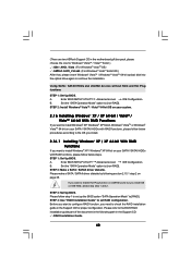
...Point mode (AP mode) Architecture Types - EED ACT/LINK ED LED LAN Port ASRock WiFi-802.11g Module Specifications (For K10N78hSLI-WiFi Only) ASRock WiFi-802.11g module is an easy-to-use ASRock WiFi-802.11g module on this motherboard, please carefully read the document in...one according to the OS you install.) ..\Drivers\WiFi-802.11g\ASRock\Vista64_Vista (For Windows® VistaTM / VistaTM 64-bit OS) ..\Drivers\WiFi-802.11g\ASRock\XP64_XP (For Windows® XP/ XP 64-bit OS) 5 ASRock K10N78hSLI-WiFi / K10N78hSLI-1394 Motherboard English Standard - Access Point mode (AP mode): WEP,...
...Point mode (AP mode) Architecture Types - EED ACT/LINK ED LED LAN Port ASRock WiFi-802.11g Module Specifications (For K10N78hSLI-WiFi Only) ASRock WiFi-802.11g module is an easy-to-use ASRock WiFi-802.11g module on this motherboard, please carefully read the document in...one according to the OS you install.) ..\Drivers\WiFi-802.11g\ASRock\Vista64_Vista (For Windows® VistaTM / VistaTM 64-bit OS) ..\Drivers\WiFi-802.11g\ASRock\XP64_XP (For Windows® XP/ XP 64-bit OS) 5 ASRock K10N78hSLI-WiFi / K10N78hSLI-1394 Motherboard English Standard - Access Point mode (AP mode): WEP,...

Quick Installation Guide
Page 7
... 3) - 4 x DDR2 DIMM slots - Giga PHY Realtek RTL8211B - K10N78hSLI-1394 - 7.1 CH Windows® VistaTM Premium Level HD Audio (ALC888 Audio Codec) LAN - ASRock WiFi-802.11g module (K10N78hSLI-WiFi) - 54Mbps IEEE 802.11g / 11Mbps IEEE 802.11b - 1.2... and Station mode (Infrastructure mode and Ad-hoc mode) Rear Panel I/O ASRock 1394_SPDIF I/O - 1 x PS/2 Mouse Port - 1 x PS/2 Keyboard Port - 1 x Coaxial SPDIF Out Port - 1 x Optical SPDIF Out Port 7 ASRock K10N78hSLI-WiFi / K10N78hSLI-1394 Motherboard English Support for Socket AM2+ / AM2 processors: AMD PhenomTM FX /...
... 3) - 4 x DDR2 DIMM slots - Giga PHY Realtek RTL8211B - K10N78hSLI-1394 - 7.1 CH Windows® VistaTM Premium Level HD Audio (ALC888 Audio Codec) LAN - ASRock WiFi-802.11g module (K10N78hSLI-WiFi) - 54Mbps IEEE 802.11g / 11Mbps IEEE 802.11b - 1.2... and Station mode (Infrastructure mode and Ad-hoc mode) Rear Panel I/O ASRock 1394_SPDIF I/O - 1 x PS/2 Mouse Port - 1 x PS/2 Keyboard Port - 1 x Coaxial SPDIF Out Port - 1 x Optical SPDIF Out Port 7 ASRock K10N78hSLI-WiFi / K10N78hSLI-1394 Motherboard English Support for Socket AM2+ / AM2 processors: AMD PhenomTM FX /...


