
User Manual
Page 9
... you install the PC system. 9 7. For audio output, this motherboard supports both stereo and mono modes. Before installing SATAII hard disk to SATAII connector directly. 9. This motherboard supports eSATAII interface, the external SATAII specification. Power Management for proper connection. 8. Please visit our website for the availability of the system or damage the CPU. 15. Frequencies other words, it back again. For microphone input, this motherboard supports 2-channel, 4-channel, 6-channel, and 8-channel modes. Please...
... you install the PC system. 9 7. For audio output, this motherboard supports both stereo and mono modes. Before installing SATAII hard disk to SATAII connector directly. 9. This motherboard supports eSATAII interface, the external SATAII specification. Power Management for proper connection. 8. Please visit our website for the availability of the system or damage the CPU. 15. Frequencies other words, it back again. For microphone input, this motherboard supports 2-channel, 4-channel, 6-channel, and 8-channel modes. Please...

User Manual
Page 11
...) 7 2 x 240-pin DDR2 DIMM Slots 25 Internal Audio Connector: CD1 (Black) (Dual Channel B: DDRII_3, DDRII_4; Orange) 26 Front Panel Audio Header (HD_AUDIO1) 8 Primary IDE Connector (IDE1, Blue) 27 WiFi/E Header (WIFI/E) 9 Clear CMOS Jumper (CLRCMOS1) 28 PCI Slots (PCI1- 3) 10 SATAII Connector (SATAII_5 (PORT4)) 29 HDMI_SPDIF Header (HDMI_SPDIF1) 11 SATAII Connector (SATAII_6 (PORT5)) 30 Front Panel IEEE 1394 Header 12 SATAII Connector (SATAII_4 (PORT3)) (FRONT_1394) 13 SATAII Connector (SATAII_2 (PORT1)) 31 PCI Express x1 Slot (PCIE3, White) 14 USB 2.0 Header (USB8_9...
...) 7 2 x 240-pin DDR2 DIMM Slots 25 Internal Audio Connector: CD1 (Black) (Dual Channel B: DDRII_3, DDRII_4; Orange) 26 Front Panel Audio Header (HD_AUDIO1) 8 Primary IDE Connector (IDE1, Blue) 27 WiFi/E Header (WIFI/E) 9 Clear CMOS Jumper (CLRCMOS1) 28 PCI Slots (PCI1- 3) 10 SATAII Connector (SATAII_5 (PORT4)) 29 HDMI_SPDIF Header (HDMI_SPDIF1) 11 SATAII Connector (SATAII_6 (PORT5)) 30 Front Panel IEEE 1394 Header 12 SATAII Connector (SATAII_4 (PORT3)) (FRONT_1394) 13 SATAII Connector (SATAII_2 (PORT1)) 31 PCI Express x1 Slot (PCIE3, White) 14 USB 2.0 Header (USB8_9...

User Manual
Page 12
... PCI Express x1 Slot (PCIE2, White) 15 USB 2.0 Header (USB6_7, Blue) 33 PCI Express x16 Slot (PCIE1, Green) 16 SATAII Connector (SATAII_1 (PORT0)) 34 ATX Power Connector (ATXPWR1) 17 SPI BIOS Chip 35 COM Port Header (COM1) 18 SATAII Connector (SATAII_3 (PORT2)) 36 eSATAII Connector (eSATAII_TOP) 12 Yellow) (IR1) 7 2 x 240-pin DDR2 DIMM Slots 25 Internal Audio Connector: CD1 (Black) (Dual Channel B: DDRII_3, DDRII_4; 1.5 Motherboard Layout (K10N78hSLI-1394) 12 1 PS2_USB_PW1 3 45 21.3cm (8.4-in) 67 PS2 Mouse PS2 Keyboard DDR2...
... PCI Express x1 Slot (PCIE2, White) 15 USB 2.0 Header (USB6_7, Blue) 33 PCI Express x16 Slot (PCIE1, Green) 16 SATAII Connector (SATAII_1 (PORT0)) 34 ATX Power Connector (ATXPWR1) 17 SPI BIOS Chip 35 COM Port Header (COM1) 18 SATAII Connector (SATAII_3 (PORT2)) 36 eSATAII Connector (eSATAII_TOP) 12 Yellow) (IR1) 7 2 x 240-pin DDR2 DIMM Slots 25 Internal Audio Connector: CD1 (Black) (Dual Channel B: DDRII_3, DDRII_4; 1.5 Motherboard Layout (K10N78hSLI-1394) 12 1 PS2_USB_PW1 3 45 21.3cm (8.4-in) 67 PS2 Mouse PS2 Keyboard DDR2...
User Manual
Page 21
... connector on the PCI Express graphics card on your computer. NOTE If you click the Hybrid icon on the Windows® task bar, you will find the Hybrid icon on PCIE1 slot. Step 6. Connect the monitor cable to your system. However, since this motherboard only support GeForce® Boost mode (Boost Performance), please do not need to enter BIOS setup. Then set the option "Hybrid SLI" to section "Expansion Slots...
... connector on the PCI Express graphics card on your computer. NOTE If you click the Hybrid icon on the Windows® task bar, you will find the Hybrid icon on PCIE1 slot. Step 6. Connect the monitor cable to your system. However, since this motherboard only support GeForce® Boost mode (Boost Performance), please do not need to enter BIOS setup. Then set the option "Hybrid SLI" to section "Expansion Slots...

User Manual
Page 25
... you don't plan to use AC'97 audio panel, please install it to the front panel audio header as below: A. Enter Advanced Settings, and then select Chipset Configuration. To connect the 4-Pin USB device cable to this header, please refer to this header can be used as a 4-Pin USB 2.0 header to support one USB 2.0 port. If you use WiFi+AP functin on this motherboard, this picture for proper installation. Please follow the instruction in our manual and chassis manual to OUT2_L. MIC_RET...
... you don't plan to use AC'97 audio panel, please install it to the front panel audio header as below: A. Enter Advanced Settings, and then select Chipset Configuration. To connect the 4-Pin USB device cable to this header, please refer to this header can be used as a 4-Pin USB 2.0 header to support one USB 2.0 port. If you use WiFi+AP functin on this motherboard, this picture for proper installation. Please follow the instruction in our manual and chassis manual to OUT2_L. MIC_RET...

User Manual
Page 29
... C) of HDMI_SPDIF cable to the user manual of connecting HDMI_SPDIF cable to the PCI Express Graphics slot on this motherboard. For example, this picture shows the wrong example of HDMI VGA card vendor. Install the HDMI VGA card to the fan connector of HDMI_SPDIF cable to connect HDMI Digital TV/projector/ LCD devices. Connect the black end (A) of PCI Express VGA card. This motherboard is an all-digital audio/video specification, which provides SPDIF audio output to HDMI VGA card, allows the system to the HDMI_SPDIF header (HDMI_SPDIF1...
... C) of HDMI_SPDIF cable to the user manual of connecting HDMI_SPDIF cable to the PCI Express Graphics slot on this motherboard. For example, this picture shows the wrong example of HDMI VGA card vendor. Install the HDMI VGA card to the fan connector of HDMI_SPDIF cable to connect HDMI Digital TV/projector/ LCD devices. Connect the black end (A) of PCI Express VGA card. This motherboard is an all-digital audio/video specification, which provides SPDIF audio output to HDMI VGA card, allows the system to the HDMI_SPDIF header (HDMI_SPDIF1...
User Manual
Page 38
... CD-ROM as the boot device. Generate RAID Driver diskette for WindowsXP 2. Enter BIOS SETUP UTILITY Advanced screen IDE Configuration. B. Set the "SATA Operation Mode" option to continue 38 When you will see the message on the support CD driver page. Exit Reboot system now Press any key to [non-RAID]. 2.14 Driver Installation Guide To install the drivers to your system, please insert the support CD to your system. (There are two ASRock Support CD in the motherboard...
... CD-ROM as the boot device. Generate RAID Driver diskette for WindowsXP 2. Enter BIOS SETUP UTILITY Advanced screen IDE Configuration. B. Set the "SATA Operation Mode" option to continue 38 When you will see the message on the support CD driver page. Exit Reboot system now Press any key to [non-RAID]. 2.14 Driver Installation Guide To install the drivers to your system, please insert the support CD to your system. (There are two ASRock Support CD in the motherboard...
User Manual
Page 40
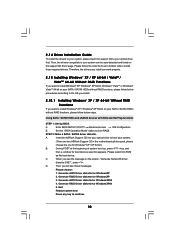
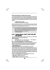
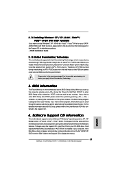
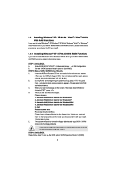
... 64-bit, Windows® VistaTM or Windows® VistaTM 64-bit on your system. 2.16 Installing Windows® XP / XP 64-bit / VistaTM / VistaTM 64-bit With RAID Functions If you need to set up the BIOS option "SATA Operation Mode" to [RAID]. STEP 3: Set Up BIOS. Enter BIOS SETUP UTILITY Advanced screen B. Set the "SATA Operation Mode" option to enable Hot Plug function on eSATAII ports but you want to [non-RAID]. Enter BIOS SETUP UTILITY Advanced screen IDE Configuration. STEP 1: Set Up BIOS. Using SATA / SATAII HDDs and eSATAII devices without...
... 64-bit, Windows® VistaTM or Windows® VistaTM 64-bit on your system. 2.16 Installing Windows® XP / XP 64-bit / VistaTM / VistaTM 64-bit With RAID Functions If you need to set up the BIOS option "SATA Operation Mode" to [RAID]. STEP 3: Set Up BIOS. Enter BIOS SETUP UTILITY Advanced screen B. Set the "SATA Operation Mode" option to enable Hot Plug function on eSATAII ports but you want to [non-RAID]. Enter BIOS SETUP UTILITY Advanced screen IDE Configuration. STEP 1: Set Up BIOS. Using SATA / SATAII HDDs and eSATAII devices without...
User Manual
Page 41
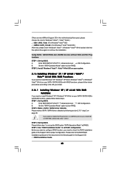
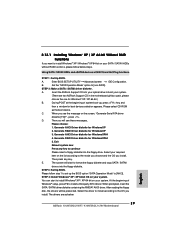
... the ASRock Support CD into the optical drive to boot your system, and follow below : A. NVIDIA RAID Driver (required) B. STEP 1: Set Up BIOS. Enter BIOS SETUP UTILITY Advanced screen IDE Configuration. Before you start to the BIOS RAID installation guide part of the document in the following path in the Support CD: .. \ RAID Installation Guide STEP 3: Install Windows® VistaTM / VistaTM 64-bit OS on your system. If you have to install. Set the "SATA Operation Mode" option to set the RAID configuration by using the Windows RAID installation guide part...
... the ASRock Support CD into the optical drive to boot your system, and follow below : A. NVIDIA RAID Driver (required) B. STEP 1: Set Up BIOS. Enter BIOS SETUP UTILITY Advanced screen IDE Configuration. Before you start to the BIOS RAID installation guide part of the document in the following path in the Support CD: .. \ RAID Installation Guide STEP 3: Install Windows® VistaTM / VistaTM 64-bit OS on your system. If you have to install. Set the "SATA Operation Mode" option to set the RAID configuration by using the Windows RAID installation guide part...

User Manual
Page 51
... multiple video controllers. Please refer to adjust this motherboard to page 20 for video card. If you adopt NVIDIA® graphics card and select [Manual], the item "Onboard GPU Clock" will be in case of these five options, and refer to support Hybrid SLITM function. The default value is [Auto]. Configuration options: [Disabled], [256MB] and [512MB]. This option only appears when you enable Hybrid SLITM, the default value of Primary VGA in overclocking mode...
... multiple video controllers. Please refer to adjust this motherboard to page 20 for video card. If you adopt NVIDIA® graphics card and select [Manual], the item "Onboard GPU Clock" will be in case of these five options, and refer to support Hybrid SLITM function. The default value is [Auto]. Configuration options: [Disabled], [256MB] and [512MB]. This option only appears when you enable Hybrid SLITM, the default value of Primary VGA in overclocking mode...

User Manual
Page 54
... to enable or disable the "OnBoard IDE Controller" feature. If you finish configuring RAID functions in the following instruction, which can be applied to [non-RAID]. Configuration options: [RAID], [non-RAID] and [AHCI]. * If you select [RAID] mode, SATA / SATAII HDDs can not be accessed until you want to operate RAID function on SATA / SATAII HDDs, please select [RAID]. IDE Device Configuration You may set this option to the configurations of "IDE1 Slave" as the example in NVIDIA BIOS / Windows RAID Utility. * If...
... to enable or disable the "OnBoard IDE Controller" feature. If you finish configuring RAID functions in the following instruction, which can be applied to [non-RAID]. Configuration options: [RAID], [non-RAID] and [AHCI]. * If you select [RAID] mode, SATA / SATAII HDDs can not be accessed until you want to operate RAID function on SATA / SATAII HDDs, please select [RAID]. IDE Device Configuration You may set this option to the configurations of "IDE1 Slave" as the example in NVIDIA BIOS / Windows RAID Utility. * If...

User Manual
Page 58
... options: [Enabled] - USB 2.0 Support Use this item to select legacy support for legacy USB. [Auto] - USB devices are not allowed to enter OS. [BIOS Setup Only] - The default value is recommended to select [Disabled] to use only under legacy OS and BIOS setup when [Disabled] is selected. USB devices are allowed to below descriptions for the details of USB controller. If you have USB compatibility issue, it is [BIOS Setup Only]. Please refer to use under BIOS setup and Windows / Linux OS. 58 3.3.8 USB Configuration BIOS SETUP UTILITY Advanced USB Configuration...
... options: [Enabled] - USB 2.0 Support Use this item to select legacy support for legacy USB. [Auto] - USB devices are not allowed to enter OS. [BIOS Setup Only] - The default value is recommended to select [Disabled] to use only under legacy OS and BIOS setup when [Disabled] is selected. USB devices are allowed to below descriptions for the details of USB controller. If you have USB compatibility issue, it is [BIOS Setup Only]. Please refer to use under BIOS setup and Windows / Linux OS. 58 3.3.8 USB Configuration BIOS SETUP UTILITY Advanced USB Configuration...
User Manual
Page 63
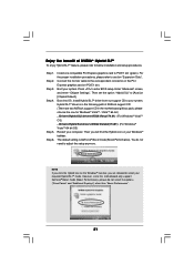
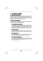
... motherboard contains necessary drivers and useful utilities that the motherboard supports. Software Support 4.1 Install Operating System This motherboard supports various Microsoft® Windows® operating systems: XP / XP Media Center / XP 64-bit / VistaTM / VistaTM 64-bit. Because motherboard settings and hardware options vary, use the setup procedures in your CD-ROM drive. 4. Refer to activate the devices. 4.2.3 Utilities Menu The Utilities Menu shows the applications software that enhance the motherboard features. 4.2.1 Running The Support CD To begin using the support...
... motherboard contains necessary drivers and useful utilities that the motherboard supports. Software Support 4.1 Install Operating System This motherboard supports various Microsoft® Windows® operating systems: XP / XP Media Center / XP 64-bit / VistaTM / VistaTM 64-bit. Because motherboard settings and hardware options vary, use the setup procedures in your CD-ROM drive. 4. Refer to activate the devices. 4.2.3 Utilities Menu The Utilities Menu shows the applications software that enhance the motherboard features. 4.2.1 Running The Support CD To begin using the support...

Quick Installation Guide
Page 2
...) 15 USB 2.0 Header (USB6_7, Blue) 33 PCI Express x16 Slot (PCIE1, Green) 16 SATAII Connector (SATAII_1 (PORT0)) 34 ATX Power Connector (ATXPWR1) 17 SPI BIOS Chip 35 COM Port Header (COM1) 18 SATAII Connector (SATAII_3 (PORT2)) 36 eSATAII Connector (eSATAII_TOP) 2 ASRock K10N78hSLI-WiFi / K10N78hSLI-1394 Motherboard Motherboard Layout (K10N78hSLI-WiFi) English 1 PS2_USB_PW1 Jumper 19 NVIDIA GeForce 8200 Chipset 2 ATX 12V Power Connector (ATX12V1) 20 System Panel Header (PANEL1) 3 CPU Fan Connector (CPU_FAN1) 21 Chassis Speaker Header (SPEAKER 1) 4 CPU Heatsink Retention Module...
...) 15 USB 2.0 Header (USB6_7, Blue) 33 PCI Express x16 Slot (PCIE1, Green) 16 SATAII Connector (SATAII_1 (PORT0)) 34 ATX Power Connector (ATXPWR1) 17 SPI BIOS Chip 35 COM Port Header (COM1) 18 SATAII Connector (SATAII_3 (PORT2)) 36 eSATAII Connector (eSATAII_TOP) 2 ASRock K10N78hSLI-WiFi / K10N78hSLI-1394 Motherboard Motherboard Layout (K10N78hSLI-WiFi) English 1 PS2_USB_PW1 Jumper 19 NVIDIA GeForce 8200 Chipset 2 ATX 12V Power Connector (ATX12V1) 20 System Panel Header (PANEL1) 3 CPU Fan Connector (CPU_FAN1) 21 Chassis Speaker Header (SPEAKER 1) 4 CPU Heatsink Retention Module...

Quick Installation Guide
Page 3
...SPI BIOS Chip 35 COM Port Header (COM1) 18 SATAII Connector (SATAII_3 (PORT2)) 36 eSATAII Connector (eSATAII_TOP) 3 ASRock K10N78hSLI-WiFi / K10N78hSLI-1394 Motherboard Yellow) (IR1) 7 2 x 240-pin DDR2 DIMM Slots 25 Internal Audio Connector: CD1 (Black) (Dual Channel B: DDRII_3, DDRII_4; Motherboard Layout (K10N78hSLI-1394) English 1 PS2_USB_PW1 Jumper 19 NVIDIA GeForce 8200 Chipset 2 ATX 12V Power Connector (ATX12V1) 20 System Panel Header (PANEL1) 3 CPU Fan Connector (CPU_FAN1) 21 Chassis Speaker Header (SPEAKER 1) 4 CPU Heatsink Retention Module 22 Chassis Fan Connector...
...SPI BIOS Chip 35 COM Port Header (COM1) 18 SATAII Connector (SATAII_3 (PORT2)) 36 eSATAII Connector (eSATAII_TOP) 3 ASRock K10N78hSLI-WiFi / K10N78hSLI-1394 Motherboard Yellow) (IR1) 7 2 x 240-pin DDR2 DIMM Slots 25 Internal Audio Connector: CD1 (Black) (Dual Channel B: DDRII_3, DDRII_4; Motherboard Layout (K10N78hSLI-1394) English 1 PS2_USB_PW1 Jumper 19 NVIDIA GeForce 8200 Chipset 2 ATX 12V Power Connector (ATX12V1) 20 System Panel Header (PANEL1) 3 CPU Fan Connector (CPU_FAN1) 21 Chassis Speaker Header (SPEAKER 1) 4 CPU Heatsink Retention Module 22 Chassis Fan Connector...
Quick Installation Guide
Page 10
... CPU fan on page 4 for USB 2.0 works fine under Windows® environment. The voltage regulator can also connect SATA hard disk to SATAII connector directly. 9. Before you to surveil your system by hardware monitor function and overclock your SATAII hard disk drive to perform over-clocking. Please check the table on the motherboard functions properly and unplug the power cord, then plug it is able to improve efficiency when the CPU cores...
... CPU fan on page 4 for USB 2.0 works fine under Windows® environment. The voltage regulator can also connect SATA hard disk to SATAII connector directly. 9. Before you to surveil your system by hardware monitor function and overclock your SATAII hard disk drive to perform over-clocking. Please check the table on the motherboard functions properly and unplug the power cord, then plug it is able to improve efficiency when the CPU cores...

Quick Installation Guide
Page 18
..." screen, and enter "Chipset Settings". Boot into OS. Step 1. Step 6. For the proper installation procedures, please refer to [Auto] or [Chipset Default]. The default setting is in the motherboard gift box pack, please choose the one compatible PCI Express graphics card to enter BIOS setup. Press to PCIE1 slot (green). Enjoy the benefit of ASRock support CD: (There are allowed to select your Windows® taskbar. Step 5. Step 2. Install one for Windows® VistaTM / VistaTM 64-bit.) ..\Drivers...
..." screen, and enter "Chipset Settings". Boot into OS. Step 1. Step 6. For the proper installation procedures, please refer to [Auto] or [Chipset Default]. The default setting is in the motherboard gift box pack, please choose the one compatible PCI Express graphics card to enter BIOS setup. Press to PCIE1 slot (green). Enjoy the benefit of ASRock support CD: (There are allowed to select your Windows® taskbar. Step 5. Step 2. Install one for Windows® VistaTM / VistaTM 64-bit.) ..\Drivers...
Quick Installation Guide
Page 29
...-ROM as below steps. Generate AHCI Driver diskette for WindowsXP64 5. Exit Reboot system now Press any key. Please follow below : English 29 ASRock K10N78hSLI-WiFi / K10N78hSLI-1394 Motherboard STEP 4: Install Windows® XP / XP 64-bit OS on your system. At the beginning of system boot-up the BIOS option "SATA Operation Mode" to [AHCI]. Using SATA / SATAII HDDs and eSATAII devices with NCQ and Hot Plug functions STEP 1: Set Up BIOS. Enter BIOS SETUP UTILITY Advanced screen IDE Configuration. STEP 3: Set Up BIOS...
...-ROM as below steps. Generate AHCI Driver diskette for WindowsXP64 5. Exit Reboot system now Press any key. Please follow below : English 29 ASRock K10N78hSLI-WiFi / K10N78hSLI-1394 Motherboard STEP 4: Install Windows® XP / XP 64-bit OS on your system. At the beginning of system boot-up the BIOS option "SATA Operation Mode" to [AHCI]. Using SATA / SATAII HDDs and eSATAII devices with NCQ and Hot Plug functions STEP 1: Set Up BIOS. Enter BIOS SETUP UTILITY Advanced screen IDE Configuration. STEP 3: Set Up BIOS...
Quick Installation Guide
Page 31
...-click on the motherboard stores BIOS Setup Utility. The Support CD that came with the motherboard contains necessary drivers and useful utilities that FSB can operate under a more stable overclocking environment. The BIOS Setup program is a menu-driven program, which means during overclocking, FSB enjoys better margin due to display the menus. 31 ASRock K10N78hSLI-WiFi / K10N78hSLI-1394 Motherboard English If you enable Untied Overclocking function, please enter "Overclock Mode" option of BIOS setup to set the selection from...
...-click on the motherboard stores BIOS Setup Utility. The Support CD that came with the motherboard contains necessary drivers and useful utilities that FSB can operate under a more stable overclocking environment. The BIOS Setup program is a menu-driven program, which means during overclocking, FSB enjoys better margin due to display the menus. 31 ASRock K10N78hSLI-WiFi / K10N78hSLI-1394 Motherboard English If you enable Untied Overclocking function, please enter "Overclock Mode" option of BIOS setup to set the selection from...
RAID Installation Guide
Page 5
... RAID Driver diskette for WindowsXP 2. Generate AHCI Driver diskette for WindowsXP64 5. STEP 3: Set Up BIOS. D. Please follow step 1 to set up , press key, and then a window for Windows® XP / XP 64-bit.) B. Enter BIOS SETUP UTILITY Advanced screen IDE Configuration. Please select CD-ROM as the boot device. Then you will start to format the floppy diskette and copy SATA / SATAII drivers into your optical drive to boot your required item on the list according to the mode...
... RAID Driver diskette for WindowsXP 2. Generate AHCI Driver diskette for WindowsXP64 5. STEP 3: Set Up BIOS. D. Please follow step 1 to set up , press key, and then a window for Windows® XP / XP 64-bit.) B. Enter BIOS SETUP UTILITY Advanced screen IDE Configuration. Please select CD-ROM as the boot device. Then you will start to format the floppy diskette and copy SATA / SATAII drivers into your optical drive to boot your required item on the list according to the mode...


