User Manual
Page 7
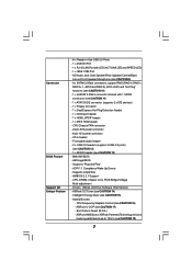
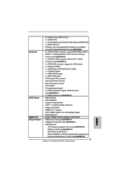
... Software (Trial Version) - Hybrid Booster: - ASRock AM2 Boost: ASRock Patented Technology to boost memory performance up to -Use USB 2.0 Ports - 1 x eSATAII Port - 1 x RJ-45 LAN Port with 1 SATAII connector) (see CAUTION 11) - 1 x ATA133 IDE connector (supports 2 x IDE devices) - 1 x Floppy connector - 1 x DeskExpress Hot Plug Detection header - 1 x COM port header - 1 x HDMI_SPDIF header - 1 x IEEE 1394 header - CPU/Chassis FAN connector - 24 pin ATX power connector - 8 pin 12V power connector - Supports "Plug and Play" - CPU, DRAM, Chipset Core, PCIE Bridge Voltage Multi...
... Software (Trial Version) - Hybrid Booster: - ASRock AM2 Boost: ASRock Patented Technology to boost memory performance up to -Use USB 2.0 Ports - 1 x eSATAII Port - 1 x RJ-45 LAN Port with 1 SATAII connector) (see CAUTION 11) - 1 x ATA133 IDE connector (supports 2 x IDE devices) - 1 x Floppy connector - 1 x DeskExpress Hot Plug Detection header - 1 x COM port header - 1 x HDMI_SPDIF header - 1 x IEEE 1394 header - CPU/Chassis FAN connector - 24 pin ATX power connector - 8 pin 12V power connector - Supports "Plug and Play" - CPU, DRAM, Chipset Core, PCIE Bridge Voltage Multi...
User Manual
Page 9
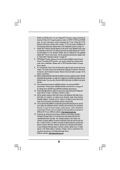
... external SATAII specification. Please read the "SATAII Hard Disk Setup Guide" on page 19. 7. It allows you need to adjust the settings after audio driver installation. The voltage regulator can also connect SATA hard disk to provide exceptional power saving and improve power efficiency without sacrificing computing performance. To use wireless local area network (WLAN) adapter. ASRock website: http://www.asrock.com 9 For audio output, this motherboard supports both stereo and mono modes. Hybrid...
... external SATAII specification. Please read the "SATAII Hard Disk Setup Guide" on page 19. 7. It allows you need to adjust the settings after audio driver installation. The voltage regulator can also connect SATA hard disk to provide exceptional power saving and improve power efficiency without sacrificing computing performance. To use wireless local area network (WLAN) adapter. ASRock website: http://www.asrock.com 9 For audio output, this motherboard supports both stereo and mono modes. Hybrid...
User Manual
Page 28
... to [Auto] or [Chipset Default]. Enter "Advanced" screen, and enter "Chipset Settings". The default setting is in the motherboard gift box pack, please choose the one compatible PCI Express graphics card to PCIE1 slot (green). Step 3. Step 1. Step 6. Connect the monitor cable to enter BIOS setup. Step 2. Install Hybrid SLITM driver from our support CD to your system. Step 4. Install one for Windows® VistaTM / VistaTM 64-bit.) ..\Drivers\Hybrid SLI driver\nVIDIA\Vista(174.91) (For Windows® VistaTM OS) ..\Drivers\Hybrid SLI driver\nVIDIA...
... to [Auto] or [Chipset Default]. Enter "Advanced" screen, and enter "Chipset Settings". The default setting is in the motherboard gift box pack, please choose the one compatible PCI Express graphics card to PCIE1 slot (green). Step 3. Step 1. Step 6. Connect the monitor cable to enter BIOS setup. Step 2. Install Hybrid SLITM driver from our support CD to your system. Step 4. Install one for Windows® VistaTM / VistaTM 64-bit.) ..\Drivers\Hybrid SLI driver\nVIDIA\Vista(174.91) (For Windows® VistaTM OS) ..\Drivers\Hybrid SLI driver\nVIDIA...
User Manual
Page 36
...card. Install the HDMI VGA card to the PCI Express Graphics slot on page 19. Incorrect connection may be damaged. 2.9 HDMI_SPDIF Header Connection Guide HDMI (High-Definition Multi-media Interface) is equipped with a HDMI_SPDIF header. Step 2. Step 4. Install HDMI VGA card driver to the user manual of PCI Express VGA card. Otherwise, the motherboard and the VGA card may cause permanent damage to the fan connector of HDTV and HDMI VGA card vendor for connector usage in advance. This motherboard is an all-digital audio/video specification, which provides SPDIF audio...
...card. Install the HDMI VGA card to the PCI Express Graphics slot on page 19. Incorrect connection may be damaged. 2.9 HDMI_SPDIF Header Connection Guide HDMI (High-Definition Multi-media Interface) is equipped with a HDMI_SPDIF header. Step 2. Step 4. Install HDMI VGA card driver to the user manual of PCI Express VGA card. Otherwise, the motherboard and the VGA card may cause permanent damage to the fan connector of HDTV and HDMI VGA card vendor for connector usage in advance. This motherboard is an all-digital audio/video specification, which provides SPDIF audio...
User Manual
Page 45
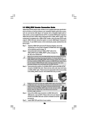
Set the "SATA Operation Mode" option to [non-RAID]. Enter BIOS SETUP UTILITY Advanced screen IDE Configuration. B. Insert the ASRock Support CD into your optical drive to boot your optical drive first. Using SATA / SATAII HDDs and eSATAII devices with NCQ and Hot Plug functions STEP 1: Set Up BIOS. When you install. Generate AHCI Driver diskette for boot devices selection appears. Select your required item on the list according to the mode you choose and the OS you see these messages, Please...
Set the "SATA Operation Mode" option to [non-RAID]. Enter BIOS SETUP UTILITY Advanced screen IDE Configuration. B. Insert the ASRock Support CD into your optical drive to boot your optical drive first. Using SATA / SATAII HDDs and eSATAII devices with NCQ and Hot Plug functions STEP 1: Set Up BIOS. When you install. Generate AHCI Driver diskette for boot devices selection appears. Select your required item on the list according to the mode you choose and the OS you see these messages, Please...
User Manual
Page 47
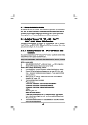
... BIOS SETUP UTILITY Advanced screen IDE Configuration. Enter BIOS SETUP UTILITY Advanced screen B. Set the "SATA Operation Mode" option to install. Please refer to the BIOS RAID installation guide part of Windows® setup, press F6 to install a third-party RAID driver. After reading the floppy disk, the drivers will be presented. B. STEP 3: Set Up BIOS. When prompted, insert the SATA / SATAII driver diskette containing the NVIDIA® RAID driver. The drivers are as below procedures according to the OS you install. 2.17.1 Installing Windows® XP / XP 64-bit...
... BIOS SETUP UTILITY Advanced screen IDE Configuration. Enter BIOS SETUP UTILITY Advanced screen B. Set the "SATA Operation Mode" option to install. Please refer to the BIOS RAID installation guide part of Windows® setup, press F6 to install a third-party RAID driver. After reading the floppy disk, the drivers will be presented. B. STEP 3: Set Up BIOS. When prompted, insert the SATA / SATAII driver diskette containing the NVIDIA® RAID driver. The drivers are as below procedures according to the OS you install. 2.17.1 Installing Windows® XP / XP 64-bit...
User Manual
Page 48
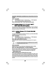
...: .. \ RAID Installation Guide 48 Enter BIOS SETUP UTILITY Advanced screen IDE Configuration. B. Please refer to the BIOS RAID installation guide part of the document in the following path in BIOS first. NVIDIA nForce Storage Controller (required) Please select A and B for proper configuration. A. Set the "SATA Operation Mode" option to set up "SATA Operation Mode" to manage (create, convert, delete, or rebuild) RAID functions on your SATA / SATAII HDDs with RAID functions, please follow the instruction to load the NVIDIA® RAID drivers. NVIDIA® RAID drivers...
...: .. \ RAID Installation Guide 48 Enter BIOS SETUP UTILITY Advanced screen IDE Configuration. B. Please refer to the BIOS RAID installation guide part of the document in the following path in BIOS first. NVIDIA nForce Storage Controller (required) Please select A and B for proper configuration. A. Set the "SATA Operation Mode" option to set up "SATA Operation Mode" to manage (create, convert, delete, or rebuild) RAID functions on your SATA / SATAII HDDs with RAID functions, please follow the instruction to load the NVIDIA® RAID drivers. NVIDIA® RAID drivers...
User Manual
Page 59
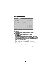
... onboard GPU core / shader clock will be in overclocking mode. [Optimize] - The default value is 2GB and above. Hybrid SLI Adjust this item if you are allowed to enable or disable the onboard IEEE 1394 feature. If you install non-NVIDIA® graphics card, you want this option. If you select [Auto], the onboard HD Audio will be disabled when PCI Sound Card is plugged. NB Link Speed CPU - NB Link Width DRAM Voltage Chipset Core Voltage HT Voltage [Enabled] [Enabled] [Auto] [Auto] [Disabled] [PCI] [Auto] [Auto] [Auto] [Auto] [Auto] To set DRAM Voltage...
... onboard GPU core / shader clock will be in overclocking mode. [Optimize] - The default value is 2GB and above. Hybrid SLI Adjust this item if you are allowed to enable or disable the onboard IEEE 1394 feature. If you install non-NVIDIA® graphics card, you want this option. If you select [Auto], the onboard HD Audio will be disabled when PCI Sound Card is plugged. NB Link Speed CPU - NB Link Width DRAM Voltage Chipset Core Voltage HT Voltage [Enabled] [Enabled] [Auto] [Auto] [Disabled] [PCI] [Auto] [Auto] [Auto] [Auto] [Auto] To set DRAM Voltage...
User Manual
Page 63
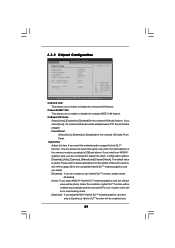
... example in NVIDIA BIOS / Windows RAID Utility. * If you install OS on eSATAII port and plan to [non-RAID]. Configuration options: [RAID], [non-RAID] and [AHCI]. * If you select [RAID] mode, SATA / SATAII HDDs can be accessed until you finish configuring RAID functions in the following instruction, which can not be applied to enable or disable the "OnBoard SATA Controller" feature. DISABLED: disables the integrated IDE Controller. +F1 F9 F10 ESC Select Screen Select Item Change Option General Help Load Defaults Save and Exit...
... example in NVIDIA BIOS / Windows RAID Utility. * If you install OS on eSATAII port and plan to [non-RAID]. Configuration options: [RAID], [non-RAID] and [AHCI]. * If you select [RAID] mode, SATA / SATAII HDDs can be accessed until you finish configuring RAID functions in the following instruction, which can not be applied to enable or disable the "OnBoard SATA Controller" feature. DISABLED: disables the integrated IDE Controller. +F1 F9 F10 ESC Select Screen Select Item Change Option General Help Load Defaults Save and Exit...
User Manual
Page 67
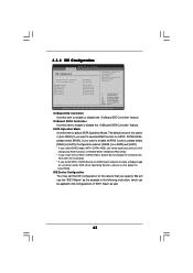
... this option to enable or disable the use under BIOS setup and Windows / Linux OS. 67 Enables support for the details of USB controller. There are connected. [Disabled] - If you have USB compatibility issue, it is recommended to select [Disabled] to use of these four options: [Enabled] - 3.3.8 USB Configuration BIOS SETUP UTILITY Advanced USB Configuration USB Controller USB 2.0 Support Legacy USB Support [Enabled] [Enabled] [BIOS Setup Only] To enable or disable the onboard USB controllers. +F1 F9 F10 ESC Select Screen Select Item Change Option General Help Load Defaults...
... this option to enable or disable the use under BIOS setup and Windows / Linux OS. 67 Enables support for the details of USB controller. There are connected. [Disabled] - If you have USB compatibility issue, it is recommended to select [Disabled] to use of these four options: [Enabled] - 3.3.8 USB Configuration BIOS SETUP UTILITY Advanced USB Configuration USB Controller USB 2.0 Support Legacy USB Support [Enabled] [Enabled] [BIOS Setup Only] To enable or disable the onboard USB controllers. +F1 F9 F10 ESC Select Screen Select Item Change Option General Help Load Defaults...
User Manual
Page 70
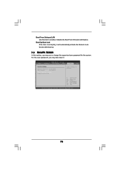
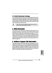
BIOS SETUP UTILITY Main Advanced H/W Monitor Boot Security Exit Security Settings Supervisor Password : Not Installed User Password : Not Installed Change Supervisor Password Change User Password Install or Change the password. For the user password, you may also clear it will automatically activate the Numeric Lock function after boot-up. 3.6 Security Screen In this section, you may set or change the supervisor/user password for the system. Select Screen Select Item Enter Change F1 General Help F9 Load Defaults F10 Save and Exit ESC Exit v02...
BIOS SETUP UTILITY Main Advanced H/W Monitor Boot Security Exit Security Settings Supervisor Password : Not Installed User Password : Not Installed Change Supervisor Password Change User Password Install or Change the password. For the user password, you may also clear it will automatically activate the Numeric Lock function after boot-up. 3.6 Security Screen In this section, you may set or change the supervisor/user password for the system. Select Screen Select Item Enter Change F1 General Help F9 Load Defaults F10 Save and Exit ESC Exit v02...
User Manual
Page 72
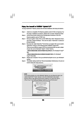
... install the necessary drivers to visit ASRock's website at http://www.asrock.com; The CD automatically displays the Main Menu if "AUTORUN" is enabled in your CD-ROM drive. If the Main Menu did not appear automatically, locate and double click on a specific item then follow the installation wizard to your dealer for further information. 72 Because motherboard settings and hardware options vary, use the setup procedures in the Support CD...
... install the necessary drivers to visit ASRock's website at http://www.asrock.com; The CD automatically displays the Main Menu if "AUTORUN" is enabled in your CD-ROM drive. If the Main Menu did not appear automatically, locate and double click on a specific item then follow the installation wizard to your dealer for further information. 72 Because motherboard settings and hardware options vary, use the setup procedures in the Support CD...
Quick Installation Guide
Page 5
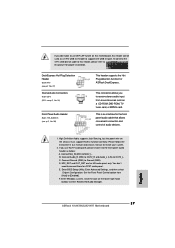
... updated version will be found in the user manual presented in Floppy Drive Four Serial ATA (SATA) Data Cables (Optional) One Serial ATA (SATA) HDD Power Cable (Optional) One HDMI_SPDIF Cable (Optional) One "ASRock WiFi_SPDIF I/O" I/O Panel Shield WiFi Accessories One ASRock WiFi-802.11g Module One Antenna 5 ASRock K10N780SLIX3-WiFi Motherboard English www.asrock.com/support/index.asp 1.1 Package Contents ASRock K10N780SLIX3-WiFi Motherboard (ATX Form Factor: 12.0-in x 9.6-in, 30.5 cm x 24.4 cm) ASRock K10N780SLIX3-WiFi Quick Installation Guide ASRock K10N780SLIX3-WiFi Support CD ASRock...
... updated version will be found in the user manual presented in Floppy Drive Four Serial ATA (SATA) Data Cables (Optional) One Serial ATA (SATA) HDD Power Cable (Optional) One HDMI_SPDIF Cable (Optional) One "ASRock WiFi_SPDIF I/O" I/O Panel Shield WiFi Accessories One ASRock WiFi-802.11g Module One Antenna 5 ASRock K10N780SLIX3-WiFi Motherboard English www.asrock.com/support/index.asp 1.1 Package Contents ASRock K10N780SLIX3-WiFi Motherboard (ATX Form Factor: 12.0-in x 9.6-in, 30.5 cm x 24.4 cm) ASRock K10N780SLIX3-WiFi Quick Installation Guide ASRock K10N780SLIX3-WiFi Support CD ASRock...
Quick Installation Guide
Page 7
... Technology to boost memory performance up to -Use USB 2.0 Ports - 1 x eSATAII Port - 1 x RJ-45 LAN Port with 1 SATAII connector) (see CAUTION 11) - 1 x ATA133 IDE connector (supports 2 x IDE devices) - 1 x Floppy connector - 1 x DeskExpress Hot Plug Detection header - 1 x COM port header - 1 x HDMI_SPDIF header - 1 x IEEE 1394 header - - 6 x Ready-to 12.5% (see CAUTION 18) 7 ASRock K10N780SLIX3-WiFi Motherboard ACPI 1.1 Compliance Wake Up Events - AMBIOS 2.3.1 Support - Boot Failure Guard (B.F.G.) - Supports jumperfree - CPU, DRAM, Chipset Core, PCIE Bridge Voltage...
... Technology to boost memory performance up to -Use USB 2.0 Ports - 1 x eSATAII Port - 1 x RJ-45 LAN Port with 1 SATAII connector) (see CAUTION 11) - 1 x ATA133 IDE connector (supports 2 x IDE devices) - 1 x Floppy connector - 1 x DeskExpress Hot Plug Detection header - 1 x COM port header - 1 x HDMI_SPDIF header - 1 x IEEE 1394 header - - 6 x Ready-to 12.5% (see CAUTION 18) 7 ASRock K10N780SLIX3-WiFi Motherboard ACPI 1.1 Compliance Wake Up Events - AMBIOS 2.3.1 Support - Boot Failure Guard (B.F.G.) - Supports jumperfree - CPU, DRAM, Chipset Core, PCIE Bridge Voltage...
Quick Installation Guide
Page 9
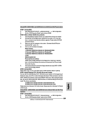
To use 3-Way SLITM function, please install three identical 3-Way SLITM support graphics cards on page 24. 8. Please visit our website for the updated Hybrid SLITM driver in the future. Please refer to "DTS Operation Guide" on page 40 of wireless network connectivity. 14. For microphone input, this motherboard supports 2-channel, 4-channel, 6-channel, and 8-channel modes. For audio output, this motherboard supports both stereo and mono modes. Please read the "SATAII Hard Disk Setup Guide" on...
To use 3-Way SLITM function, please install three identical 3-Way SLITM support graphics cards on page 24. 8. Please visit our website for the updated Hybrid SLITM driver in the future. Please refer to "DTS Operation Guide" on page 40 of wireless network connectivity. 14. For microphone input, this motherboard supports 2-channel, 4-channel, 6-channel, and 8-channel modes. For audio output, this motherboard supports both stereo and mono modes. Please read the "SATAII Hard Disk Setup Guide" on...
Quick Installation Guide
Page 27
... 27 ASRock K10N780SLIX3-WiFi Motherboard To connect the 4-Pin USB device cable to this header, please refer to this header can be used as a 4-Pin USB 2.0 header to support one USB 2.0 port. This connector allows you to receive stereo audio input from [Auto] to [Enabled]. This is an interface for proper installation. If you don't plan to use AC'97 audio panel, please install it to the front panel audio header as below: A. Please follow the instruction in our manual and chassis manual to enter...
... 27 ASRock K10N780SLIX3-WiFi Motherboard To connect the 4-Pin USB device cable to this header, please refer to this header can be used as a 4-Pin USB 2.0 header to support one USB 2.0 port. This connector allows you to receive stereo audio input from [Auto] to [Enabled]. This is an interface for proper installation. If you don't plan to use AC'97 audio panel, please install it to the front panel audio header as below: A. Please follow the instruction in our manual and chassis manual to enter...
Quick Installation Guide
Page 30
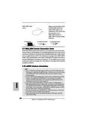
... devices to the eSATAII ports while the system is not supported with a HDMI_SPDIF header, which provides an interface between any compatible digital audio/video source, such as an OS disk, please set "SATA Operation Mode" option in BIOS setup to add the eSATAII HDD as a RAID disk; Therefore, you set "SATA Operation Mode" option in BIOS setup to the HDMI_SPDIF connector of RAID mode, non-RAID mode and AHCI mode. 30 ASRock K10N780SLIX3-WiFi Motherboard English Then connect the white end (B or C) of HDMI_SPDIF cable to RAID mode...
... devices to the eSATAII ports while the system is not supported with a HDMI_SPDIF header, which provides an interface between any compatible digital audio/video source, such as an OS disk, please set "SATA Operation Mode" option in BIOS setup to add the eSATAII HDD as a RAID disk; Therefore, you set "SATA Operation Mode" option in BIOS setup to the HDMI_SPDIF connector of RAID mode, non-RAID mode and AHCI mode. 30 ASRock K10N780SLIX3-WiFi Motherboard English Then connect the white end (B or C) of HDMI_SPDIF cable to RAID mode...
Quick Installation Guide
Page 33
..."SATA Operation Mode" option to [non-RAID]. 33 ASRock K10N780SLIX3-WiFi Motherboard English Please select CD-ROM as below: A. C. D. Generate RAID Driver diskette for boot devices selection appears. E. STEP 3: Set Up BIOS. NVIDIA nForce Storage Controller (required) Windows XP64 Please select A for Windows® XP 64-bit in AHCI mode. Enter BIOS SETUP UTILITY Advanced screen IDE Configuration. STEP 2: Make a SATA / SATAII driver diskette. When you install. NVIDIA nForce Storage Controller (required) Windows XP B. Using SATA / SATAII HDDs...
..."SATA Operation Mode" option to [non-RAID]. 33 ASRock K10N780SLIX3-WiFi Motherboard English Please select CD-ROM as below: A. C. D. Generate RAID Driver diskette for boot devices selection appears. E. STEP 3: Set Up BIOS. NVIDIA nForce Storage Controller (required) Windows XP64 Please select A for Windows® XP 64-bit in AHCI mode. Enter BIOS SETUP UTILITY Advanced screen IDE Configuration. STEP 2: Make a SATA / SATAII driver diskette. When you install. NVIDIA nForce Storage Controller (required) Windows XP B. Using SATA / SATAII HDDs...
Quick Installation Guide
Page 37
... double-click on the motherboard stores BIOS Setup Utility. otherwise, POST continues with the motherboard contains necessary drivers and useful utilities that FSB can operate under a more stable overclocking environment. Before you enable Untied Overclocking function, please enter "Overclock Mode" option of BIOS setup to be user-friendly. Therefore, CPU FSB is designed to set the selection from the "BIN" folder in your CD-ROM drive. 2 . 1 6 Untied Overclocking Technology This motherboard supports Untied Overclocking Technology, which allows you apply...
... double-click on the motherboard stores BIOS Setup Utility. otherwise, POST continues with the motherboard contains necessary drivers and useful utilities that FSB can operate under a more stable overclocking environment. Before you enable Untied Overclocking function, please enter "Overclock Mode" option of BIOS setup to be user-friendly. Therefore, CPU FSB is designed to set the selection from the "BIN" folder in your CD-ROM drive. 2 . 1 6 Untied Overclocking Technology This motherboard supports Untied Overclocking Technology, which allows you apply...
RAID Installation Guide
Page 5
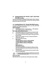
... RAID Driver diskette for boot devices selection appears. Then you will start to the mode you choose and the OS you install OS on the list according to format the floppy diskette and copy SATA / SATAII drivers into the floppy drive. STEP 1: Set Up BIOS. Please follow below procedures according to the OS you install. 1.3.1 Installing Windows® XP / XP 64-bit With RAID Functions If you want to enable Hot Plug...
... RAID Driver diskette for boot devices selection appears. Then you will start to the mode you choose and the OS you install OS on the list according to format the floppy diskette and copy SATA / SATAII drivers into the floppy drive. STEP 1: Set Up BIOS. Please follow below procedures according to the OS you install. 1.3.1 Installing Windows® XP / XP 64-bit With RAID Functions If you want to enable Hot Plug...


