RAID Installation Guide
Page 2
...) RAID 1 is equipped with six SATA / SATAII ports, you may choose to use RAID 0, RAID 1, RAID 0+1, JBOD, or RAID 5 function with your motherboard provides in advance and follow the instruction in this section to create RAID arrays. 1.1 Introduction to RAID The term "RAID" stands for you to configure...Disks", which is called data mirroring that optimizes two identical hard disk drives to configure RAID. Please refer to the RAID functions your motherboard according to the SATA / SATAII HDDs amount you can improve the access performance, it does not provide any HDDs of the RAID 0...
...) RAID 1 is equipped with six SATA / SATAII ports, you may choose to use RAID 0, RAID 1, RAID 0+1, JBOD, or RAID 5 function with your motherboard provides in advance and follow the instruction in this section to create RAID arrays. 1.1 Introduction to RAID The term "RAID" stands for you to configure...Disks", which is called data mirroring that optimizes two identical hard disk drives to configure RAID. Please refer to the RAID functions your motherboard according to the SATA / SATAII HDDs amount you can improve the access performance, it does not provide any HDDs of the RAID 0...
RAID Installation Guide
Page 5
... CD into the floppy diskette. Select your system. (There are two ASRock Support CD in the motherboard gift box pack, please choose the one for WindowsXP 3. If you want to install Windows® XP or Windows® XP 64-bit on your ...
... CD into the floppy diskette. Select your system. (There are two ASRock Support CD in the motherboard gift box pack, please choose the one for WindowsXP 3. If you want to install Windows® XP or Windows® XP 64-bit on your ...
RAID Installation Guide
Page 7
... below steps. B. When you see "Where do you want to continue the installation. " page, please insert the ASRock Support CD into the optical drive again to install Windows? NOTE. Then, please set up "SATA Operation Mode" to...STEP 1: Set Up BIOS. NVIDIA® RAID drivers are in the following path in our Support CD: (There are two ASRock Support CD in the Support CD for Windows® VistaTM / VistaTM 64-bit.) .. \ I386 \ Vista (For Windows&#... still need to check the RAID installation guide in the motherboard gift box pack, please choose the one for proper configuration.
... below steps. B. When you see "Where do you want to continue the installation. " page, please insert the ASRock Support CD into the optical drive again to install Windows? NOTE. Then, please set up "SATA Operation Mode" to...STEP 1: Set Up BIOS. NVIDIA® RAID drivers are in the following path in our Support CD: (There are two ASRock Support CD in the Support CD for Windows® VistaTM / VistaTM 64-bit.) .. \ I386 \ Vista (For Windows&#... still need to check the RAID installation guide in the motherboard gift box pack, please choose the one for proper configuration.
RAID Installation Guide
Page 12
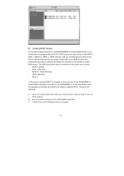
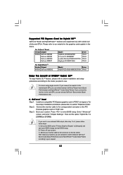
...NVRAIDMAN application. C. Creating RAID Arrays This section includes examples of creating RAID 0. If you install. Boot to create RAID 0 (Striping). B. B. If your motherboard is equipped with six SATA / SATAII ports, you may be mentioned in this section are as below: - Please refer to the RAID functions your... to the SATA / SATAII HDDs amount you plan to use RAID 0, RAID 1, RAID 0+1, JBOD, or RAID 5 function with your motherboard provides in advance and follow the instruction in this section to create RAID arrays. RAID 1: Mirroring - RAID 5 In this section, we take ...
...NVRAIDMAN application. C. Creating RAID Arrays This section includes examples of creating RAID 0. If you install. Boot to create RAID 0 (Striping). B. B. If your motherboard is equipped with six SATA / SATAII ports, you may be mentioned in this section are as below: - Please refer to the RAID functions your... to the SATA / SATAII HDDs amount you plan to use RAID 0, RAID 1, RAID 0+1, JBOD, or RAID 5 function with your motherboard provides in advance and follow the instruction in this section to create RAID arrays. RAID 1: Mirroring - RAID 5 In this section, we take ...
User Manual
Page 2
... but not limited to the contents of this manual, ASRock does not provide warranty of any interference received, including interference that may appear in this manual. CALIFORNIA, USA ONLY The Lithium battery adopted on this motherboard contains Perchlorate, a toxic substance controlled in this manual are... used only for loss of profits, loss of business, loss of data, interruption of business and the like), even if ASRock has been advised of the possibility of ...
... but not limited to the contents of this manual, ASRock does not provide warranty of any interference received, including interference that may appear in this manual. CALIFORNIA, USA ONLY The Lithium battery adopted on this motherboard contains Perchlorate, a toxic substance controlled in this manual are... used only for loss of profits, loss of business, loss of data, interruption of business and the like), even if ASRock has been advised of the possibility of ...

User Manual
Page 3
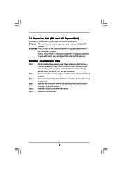
... 1080p Blu-ray (BD) / HD-DVD Playback Support 11 1.4 Passed 1080p Blu-ray (BD) / HD-DVD Films in Our Lab Test ... 12 1.5 Motherboard Layout (K10N78-1394 13 1.6 Motherboard Layout (K10N78 14 1.7 I/O Panel (K10N78-1394 15 1.8 I/O Panel (K10N78 16 2 . Introduction 5 1.1 Package Contents 5 1.2 Specifications 6 1.3 Minimum Hardware Requirement for SATA / SATAII HDDs / eSATAII Devices 43 2.15 SATA / SATAII HDD Hot Plug...
... 1080p Blu-ray (BD) / HD-DVD Playback Support 11 1.4 Passed 1080p Blu-ray (BD) / HD-DVD Films in Our Lab Test ... 12 1.5 Motherboard Layout (K10N78-1394 13 1.6 Motherboard Layout (K10N78 14 1.7 I/O Panel (K10N78-1394 15 1.8 I/O Panel (K10N78 16 2 . Introduction 5 1.1 Package Contents 5 1.2 Specifications 6 1.3 Minimum Hardware Requirement for SATA / SATAII HDDs / eSATAII Devices 43 2.15 SATA / SATAII HDD Hot Plug...
User Manual
Page 5
...://www.asrock.com If you for purchasing ASRock K10N78-1394 / K10N78 motherboard, a reliable motherboard produced under ASRock's consistently stringent quality control. Because the motherboard specifications and the BIOS software might be subject to the hardware installation. In this manual, chapter 1 and 2 contain introduction of this motherboard, please visit our website for a 3.5-in , 30.5 cm x 21.3 cm) ASRock K10N78-1394 / K10N78 Quick Installation Guide ASRock K10N78-1394 / K10N78 Support...
...://www.asrock.com If you for purchasing ASRock K10N78-1394 / K10N78 motherboard, a reliable motherboard produced under ASRock's consistently stringent quality control. Because the motherboard specifications and the BIOS software might be subject to the hardware installation. In this manual, chapter 1 and 2 contain introduction of this motherboard, please visit our website for a 3.5-in , 30.5 cm x 21.3 cm) ASRock K10N78-1394 / K10N78 Quick Installation Guide ASRock K10N78-1394 / K10N78 Support...
User Manual
Page 8
..., applying Untied Overclocking Technology, or using the thirdparty overclocking tools. ASRock AM2 Boost: ASRock Patented Technology to boost memory performance up to 5200 MT/s), and the HT Link frequency depends on this motherboard, please refer to the components and devices of memory modules on ...our website for more information. FCC, CE, WHQL * For detailed product information, please visit our website: http://www.asrock.com WARNING Please realize that there is...
..., applying Untied Overclocking Technology, or using the thirdparty overclocking tools. ASRock AM2 Boost: ASRock Patented Technology to boost memory performance up to 5200 MT/s), and the HT Link frequency depends on this motherboard, please refer to the components and devices of memory modules on ...our website for more information. FCC, CE, WHQL * For detailed product information, please visit our website: http://www.asrock.com WARNING Please realize that there is...
User Manual
Page 9
...is subject to create a wireless environment and enjoy the convenience of output phases to support 2 USB 2.0 ports. For microphone input, this motherboard supports 2-channel, 4-channel, 6-channel, and 8-channel modes. It allows you to surveil your SATAII hard disk drive to SATAII connector ... and Windows® VistaTM 64bit with ASRock WiFi-802.11g or WiFi-802. 11n module, an easy-to-use wireless local area network (WLAN) adapter. This motherboard supports eSATAII interface, the external SATAII specification. ASRock website http://www.asrock.com 14. Please visit our website for...
...is subject to create a wireless environment and enjoy the convenience of output phases to support 2 USB 2.0 ports. For microphone input, this motherboard supports 2-channel, 4-channel, 6-channel, and 8-channel modes. It allows you to surveil your SATAII hard disk drive to SATAII connector ... and Windows® VistaTM 64bit with ASRock WiFi-802.11g or WiFi-802. 11n module, an easy-to-use wireless local area network (WLAN) adapter. This motherboard supports eSATAII interface, the external SATAII specification. ASRock website http://www.asrock.com 14. Please visit our website for...
User Manual
Page 10
... damage the CPU. 17. While CPU overheat is detected, the system will automatically shutdown. If you enable this motherboard offers stepless control, it back again. ASRock website: http://www.asrock.com 16. This motherboard supports ASRock AM2 Boost overclocking technology for the operation procedures of your system. To use Intelligent Energy Saver function, please enable...
... damage the CPU. 17. While CPU overheat is detected, the system will automatically shutdown. If you enable this motherboard offers stepless control, it back again. ASRock website: http://www.asrock.com 16. This motherboard supports ASRock AM2 Boost overclocking technology for the operation procedures of your system. To use Intelligent Energy Saver function, please enable...
User Manual
Page 11
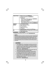
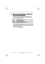
... below table for 1080p Blu-ray (BD) / HD-DVD Playback Support 1080p Blu-ray (BD) / HD-DVD playback support on this motherboard requires the proper hardware configuration. ASRock website http://www.asrock.com 11 1.3 Minimum Hardware Requirement for the minimum hardware requirement. CPU VGA Memory Suggested OS AMD Phenom X3 8400 Onboard VGA...
... below table for 1080p Blu-ray (BD) / HD-DVD Playback Support 1080p Blu-ray (BD) / HD-DVD playback support on this motherboard requires the proper hardware configuration. ASRock website http://www.asrock.com 11 1.3 Minimum Hardware Requirement for the minimum hardware requirement. CPU VGA Memory Suggested OS AMD Phenom X3 8400 Onboard VGA...

User Manual
Page 13
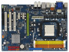
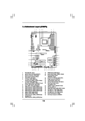
... Connector: CD1 (Black) 7 2 x 240-pin DDR2 DIMM Slots 26 Front Panel Audio Header (Dual Channel B: DDRII_3, DDRII_4; 1.5 Motherboard Layout (K10N78-1394) 12 3 45 67 21.3cm (8.4-in) 1 PS2_USB_PW1 PS2 Mouse PS2 Keyboard AM2+ FSB2.6GHz DVI_CON1 VGA1 ATX12V1 DDRII_3 (64 bit, 240...CPU_FAN1 140W CPU PCI Express 2.0 Super I/O PCIE2 PCIE3 RAID 1 FRONT_1394 HDMI_SPDIF1 1 AUDIO CODEC USB/WIFI HD_AUDIO1 CD1 1 IR1 1 FLOPPY1 PCIE1 K10N78-1394 CLRCMOS1 1 CMOS BATTERY SATAII_1 (PORT0) SATAII_3 (PORT2) SATAII_5 (PORT4) SATAII_2 (PORT1) SATAII_4 (PORT3) SATAII_6 (PORT5) PCI1 RoHS PCI2 ...
... Connector: CD1 (Black) 7 2 x 240-pin DDR2 DIMM Slots 26 Front Panel Audio Header (Dual Channel B: DDRII_3, DDRII_4; 1.5 Motherboard Layout (K10N78-1394) 12 3 45 67 21.3cm (8.4-in) 1 PS2_USB_PW1 PS2 Mouse PS2 Keyboard AM2+ FSB2.6GHz DVI_CON1 VGA1 ATX12V1 DDRII_3 (64 bit, 240...CPU_FAN1 140W CPU PCI Express 2.0 Super I/O PCIE2 PCIE3 RAID 1 FRONT_1394 HDMI_SPDIF1 1 AUDIO CODEC USB/WIFI HD_AUDIO1 CD1 1 IR1 1 FLOPPY1 PCIE1 K10N78-1394 CLRCMOS1 1 CMOS BATTERY SATAII_1 (PORT0) SATAII_3 (PORT2) SATAII_5 (PORT4) SATAII_2 (PORT1) SATAII_4 (PORT3) SATAII_6 (PORT5) PCI1 RoHS PCI2 ...
User Manual
Page 14
Yellow) 7 2 x 240-pin DDR2 DIMM Slots (Dual Channel B: DDRII_3, DDRII_4; 1.6 Motherboard Layout (K10N78) 12 3 45 21.3cm (8.4-in) 1 PS2_USB_PW1 67 PS2 Mouse PS2 Keyboard AM2+ FSB2.6GHz DVI_CON1 VGA1 USB 2.0 T: USB4 B: USB5 USB 2.0 T: USB2 B: USB3 USB...27 1 COM1 LAN PHY CPU_FAN1 140W CPU PCI Express 2.0 Super I/O PCIE2 PCIE3 RAID HDMI_SPDIF1 1 AUDIO CODEC USB/WIFI HD_AUDIO1 CD1 1 IR1 1 FLOPPY1 PCIE1 K10N78 CLRCMOS1 1 CMOS BATTERY SATAII_1 (PORT0) SATAII_3 (PORT2) SATAII_5 (PORT4) SATAII_2 (PORT1) SATAII_4 (PORT3) SATAII_6 (PORT5) PCI1 RoHS PCI2 PCI3 NVIDIA GeForce ...
Yellow) 7 2 x 240-pin DDR2 DIMM Slots (Dual Channel B: DDRII_3, DDRII_4; 1.6 Motherboard Layout (K10N78) 12 3 45 21.3cm (8.4-in) 1 PS2_USB_PW1 67 PS2 Mouse PS2 Keyboard AM2+ FSB2.6GHz DVI_CON1 VGA1 USB 2.0 T: USB4 B: USB5 USB 2.0 T: USB2 B: USB3 USB...27 1 COM1 LAN PHY CPU_FAN1 140W CPU PCI Express 2.0 Super I/O PCIE2 PCIE3 RAID HDMI_SPDIF1 1 AUDIO CODEC USB/WIFI HD_AUDIO1 CD1 1 IR1 1 FLOPPY1 PCIE1 K10N78 CLRCMOS1 1 CMOS BATTERY SATAII_1 (PORT0) SATAII_3 (PORT2) SATAII_5 (PORT4) SATAII_2 (PORT1) SATAII_4 (PORT3) SATAII_6 (PORT5) PCI1 RoHS PCI2 PCI3 NVIDIA GeForce ...
User Manual
Page 17
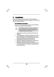
...that the power is switched off or the power cord is an ATX form factor (12.0-in x 8.4-in, 30.5 cm x 21.3 cm) motherboard. Before you handle components. 3. Unplug the power cord from the power supply. Hold components by the edges and do not over-tighten the screws!... To avoid damaging the motherboard components due to the motherboard, peripherals, and/or components. 1. 2. Installation This is detached from the wall socket before you install or remove any component, place...
...that the power is switched off or the power cord is an ATX form factor (12.0-in x 8.4-in, 30.5 cm x 21.3 cm) motherboard. Before you handle components. 3. Unplug the power cord from the power supply. Hold components by the edges and do not over-tighten the screws!... To avoid damaging the motherboard components due to the motherboard, peripherals, and/or components. 1. 2. Installation This is detached from the wall socket before you install or remove any component, place...
User Manual
Page 18
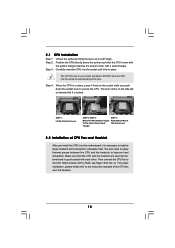
... up to the CPU FAN connector (CPU_FAN1, see Page 13/14, No. 3). The lever clicks on the socket while you install the CPU into this motherboard, it is necessary to install a larger heatsink and cooling fan to secure the CPU. Lever 90° Up STEP 1: Lift Up The Socket Lever CPU...
... up to the CPU FAN connector (CPU_FAN1, see Page 13/14, No. 3). The lever clicks on the socket while you install the CPU into this motherboard, it is necessary to install a larger heatsink and cooling fan to secure the CPU. Lever 90° Up STEP 1: Lift Up The Socket Lever CPU...
User Manual
Page 19
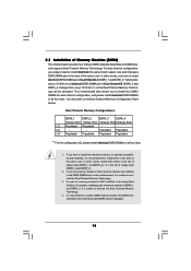
...to install four DDR2 DIMMs for dual channel configuration, and please install identical DDR2 DIMMs in the DDR2 DIMM slots on this motherboard and DIMM may refer to activate the Dual Channel Memory Technology . 4. You may be activated. 2.3 Installation of orange slots...DDRII_2 DDRII_3 DDRII_4 (Yellow Slot) (Yellow Slot) (Orange Slot) (Orange Slot) (1) Populated Populated - - (2) - - otherwise, this motherboard, it is NOT installed in the same Dual Channel, for optimal compatibility and reliability, it is unable to the Dual Channel Memory Configuration Table ...
...to install four DDR2 DIMMs for dual channel configuration, and please install identical DDR2 DIMMs in the DDR2 DIMM slots on this motherboard and DIMM may refer to activate the Dual Channel Memory Technology . 4. You may be activated. 2.3 Installation of orange slots...DDRII_2 DDRII_3 DDRII_4 (Yellow Slot) (Yellow Slot) (Orange Slot) (Orange Slot) (1) Populated Populated - - (2) - - otherwise, this motherboard, it is NOT installed in the same Dual Channel, for optimal compatibility and reliability, it is unable to the Dual Channel Memory Configuration Table ...
User Manual
Page 20
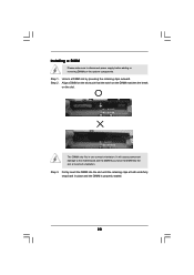
... Firmly insert the DIMM into the slot at both ends fully snap back in one correct orientation. Step 3. Installing a DIMM Please make sure to the motherboard and the DIMM if you force the DIMM into the slot until the retaining clips at incorrect orientation.
... Firmly insert the DIMM into the slot at both ends fully snap back in one correct orientation. Step 3. Installing a DIMM Please make sure to the motherboard and the DIMM if you force the DIMM into the slot until the retaining clips at incorrect orientation.
User Manual
Page 21
Green) is completely seated on this motherboard. Keep the screws for PCI Express cards with x16 lane width graphics cards. PCIE2 / PCIE3 (PCIE x1 slot; White) is used for the card before ... make sure that the power supply is switched off or the power cord is already installed in a chassis). Remove the system unit cover (if your motherboard is unplugged. Step 3. Step 5. PCIE slots: PCIE1 (PCIE x16 slot; Step 2. Remove the bracket facing the slot that have the 32-bit PCI interface. PCI...
Green) is completely seated on this motherboard. Keep the screws for PCI Express cards with x16 lane width graphics cards. PCIE2 / PCIE3 (PCIE x1 slot; White) is used for the card before ... make sure that the power supply is switched off or the power cord is already installed in a chassis). Remove the system unit cover (if your motherboard is unplugged. Step 3. Step 5. PCIE slots: PCIE1 (PCIE x16 slot; Step 2. Remove the bracket facing the slot that have the 32-bit PCI interface. PCI...
User Manual
Page 22
...Configuration for Hybrid SLITM For best Hybrid SLITM benefits, the following minimum system configuration is not required and use the motherboard GPU for non intensive graphics applications. Please visit our website for everyday computing tasks like browsing the Web, word ...additive performance. Hybrid SLITM technology today includes two primary features: GeForce® Boost and HybridPowerTM. 2.5 Hybrid SLITM Operation Guide This motherboard supports NVIDIA® Hybrid SLITM feature. Hybrid SLITM technology, based on NVIDIA®' s industry-leading SLITM technology, delivers multi-...
...Configuration for Hybrid SLITM For best Hybrid SLITM benefits, the following minimum system configuration is not required and use the motherboard GPU for non intensive graphics applications. Please visit our website for everyday computing tasks like browsing the Web, word ...additive performance. Hybrid SLITM technology today includes two primary features: GeForce® Boost and HybridPowerTM. 2.5 Hybrid SLITM Operation Guide This motherboard supports NVIDIA® Hybrid SLITM feature. Hybrid SLITM technology, based on NVIDIA®' s industry-leading SLITM technology, delivers multi-...
User Manual
Page 23
... 3. Enter "Advanced" screen, and enter "Chipset Settings". Please refer to our website for Hybrid SLITM GeForce® Boost and HybridPowerTM features are allowed to the motherboard GPU, you can choose GeForce® Boost mode (Boost Performance) only. C. After reboot your system, you plan to use onboard VGA output, after step 1 to...
... 3. Enter "Advanced" screen, and enter "Chipset Settings". Please refer to our website for Hybrid SLITM GeForce® Boost and HybridPowerTM features are allowed to the motherboard GPU, you can choose GeForce® Boost mode (Boost Performance) only. C. After reboot your system, you plan to use onboard VGA output, after step 1 to...

