User Manual
Page 3
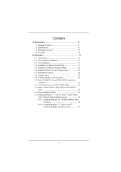
... Motherboard Layout 12 1.4 I/O Panel 13 2 Installation 14 2.1 Screw Holes 14 2.2 Pre-installation Precautions 14 2.3 CPU Installation 15 2.4 Installation of Heatsink and CPU fan 17 2.5 Installation of Memory Modules (DIMM 18 2.6 Expansion Slots (PCI and PCI Express Slots 19 2.7 Multi Monitor Feature 20 2.8 Jumpers Setup 22 2.9 Onboard Headers and Connectors 23 2.10 Serial ATA (SATA) / Serial ATAII (SATAII) Hard Disks Installation 27 2.11 Hot Plug Function for SATA / SATAII HDDs 27 2.12 SATA / SATAII HDD Hot Plug Feature and Operation Guide 28 2.13 Driver Installation Guide 30...
... Motherboard Layout 12 1.4 I/O Panel 13 2 Installation 14 2.1 Screw Holes 14 2.2 Pre-installation Precautions 14 2.3 CPU Installation 15 2.4 Installation of Heatsink and CPU fan 17 2.5 Installation of Memory Modules (DIMM 18 2.6 Expansion Slots (PCI and PCI Express Slots 19 2.7 Multi Monitor Feature 20 2.8 Jumpers Setup 22 2.9 Onboard Headers and Connectors 23 2.10 Serial ATA (SATA) / Serial ATAII (SATAII) Hard Disks Installation 27 2.11 Hot Plug Function for SATA / SATAII HDDs 27 2.12 SATA / SATAII HDD Hot Plug Feature and Operation Guide 28 2.13 Driver Installation Guide 30...

User Manual
Page 6
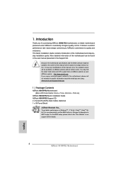
... Start Technology and Smart Connect Technology - Solid Capacitor for CPU power - Supports Hyper-Threading Technology (see CAUTION 3) - With Intel® Sandy Bridge CPU, it only supports PCIE 2.0. - 1 x PCI Express 2.0 x1 slot - 1 x PCI slot * Intel® HD Graphics Built-in Visuals and the VGA outputs can be supported only with Intel® Sandy Bridge CPU. 6 Pixel Shader 4.1, DirectX 10.1 with processors which are GPU integrated. - Supports DDR3 1600/1333/1066 non-ECC, un-buffered memory...
... Start Technology and Smart Connect Technology - Solid Capacitor for CPU power - Supports Hyper-Threading Technology (see CAUTION 3) - With Intel® Sandy Bridge CPU, it only supports PCIE 2.0. - 1 x PCI Express 2.0 x1 slot - 1 x PCI slot * Intel® HD Graphics Built-in Visuals and the VGA outputs can be supported only with Intel® Sandy Bridge CPU. 6 Pixel Shader 4.1, DirectX 10.1 with processors which are GPU integrated. - Supports DDR3 1600/1333/1066 non-ECC, un-buffered memory...

User Manual
Page 7
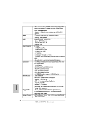
...CPU/Chassis/Power FAN connector - 24 pin ATX power connector - 8 pin 12V power connector - Max. Audio LAN Rear Panel I /O Panel - 1 x PS/2 Mouse Port - 1 x PS/2 Keyboard Port - 1 x Serial Port: COM1 - 1 x VGA Port - 4 x Ready-to 2048x1536 @ 75Hz - 5.1 CH HD Audio (VIA® VT1705 Audio Codec) - shared memory 1760MB with Intel® Sandy Bridge CPU. (see CAUTION 5) - resolution up to -Use USB 2.0 Ports - 1 x RJ-45 LAN Port with max. AMI UEFI Legal BIOS with GUI support - OEM - ASRock Extreme Tuning Utility (AXTU) (see CAUTION 4) - Max. Drivers, Utilities, AntiVirus Software...
...CPU/Chassis/Power FAN connector - 24 pin ATX power connector - 8 pin 12V power connector - Max. Audio LAN Rear Panel I /O Panel - 1 x PS/2 Mouse Port - 1 x PS/2 Keyboard Port - 1 x Serial Port: COM1 - 1 x VGA Port - 4 x Ready-to 2048x1536 @ 75Hz - 5.1 CH HD Audio (VIA® VT1705 Audio Codec) - shared memory 1760MB with Intel® Sandy Bridge CPU. (see CAUTION 5) - resolution up to -Use USB 2.0 Ports - 1 x RJ-45 LAN Port with max. AMI UEFI Legal BIOS with GUI support - OEM - ASRock Extreme Tuning Utility (AXTU) (see CAUTION 4) - Max. Drivers, Utilities, AntiVirus Software...
User Manual
Page 9
... Hardware Monitor, Fan Control, Overclocking, OC DNA and IES. About the setting of ASRock Extreme Tuning Utility (AXTU). ASRock APP Charger allows you can load the OC profile to their own system to overclock CPU frequency for the latest information. 5. This motherboard supports Dual Channel Memory Technology. You can press key during the POST or press key to BIOS setup menu to quickly charge many Apple devices simultaneously and even supports continuous charging when your USB...
... Hardware Monitor, Fan Control, Overclocking, OC DNA and IES. About the setting of ASRock Extreme Tuning Utility (AXTU). ASRock APP Charger allows you can load the OC profile to their own system to overclock CPU frequency for the latest information. 5. This motherboard supports Dual Channel Memory Technology. You can press key during the POST or press key to BIOS setup menu to quickly charge many Apple devices simultaneously and even supports continuous charging when your USB...
User Manual
Page 12
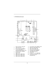
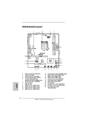
...3 CPU Fan Connector (CPU_FAN1) 4 ATX 12V Power Connector (ATX12V1 5 2 x 240-pin DDR3 DIMM Slots (Dual Channel: DDR3_A1, DDR3_B1, Blue) 6 ATX Power Connector (ATXPWR1) 7 Intel H61 Chipset 8 32Mb SPI Flash 9 SATA2 Connector (SATA2_0, Blue) 10 SATA2 Connector (SATA2_1, Blue) 11 SATA2 Connector (SATA2_2, Blue) 12 SATA2 Connector (SATA2_3, Blue) 13 Chassis Speaker Header (SPEAKER 1, White) 14 System Panel Header (PANEL1, White) 15 USB 2.0 Header (USB4_5, Blue) 16 USB 2.0 Header (USB6_7, Blue) 17 Chassis Fan Connector (CHA_FAN1) 18 Clear CMOS Jumper (CLRCMOS1) 19 Infrared Module Header (IR1) 20 PCI...
...3 CPU Fan Connector (CPU_FAN1) 4 ATX 12V Power Connector (ATX12V1 5 2 x 240-pin DDR3 DIMM Slots (Dual Channel: DDR3_A1, DDR3_B1, Blue) 6 ATX Power Connector (ATXPWR1) 7 Intel H61 Chipset 8 32Mb SPI Flash 9 SATA2 Connector (SATA2_0, Blue) 10 SATA2 Connector (SATA2_1, Blue) 11 SATA2 Connector (SATA2_2, Blue) 12 SATA2 Connector (SATA2_3, Blue) 13 Chassis Speaker Header (SPEAKER 1, White) 14 System Panel Header (PANEL1, White) 15 USB 2.0 Header (USB4_5, Blue) 16 USB 2.0 Header (USB6_7, Blue) 17 Chassis Fan Connector (CHA_FAN1) 18 Clear CMOS Jumper (CLRCMOS1) 19 Infrared Module Header (IR1) 20 PCI...

User Manual
Page 20
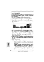
...] to enable the function of the add-on PCI Express VGA card on VGA card is no need to set up a multi-monitor display. If you can adjust the parameters of the system memory. Install the PCI Express VGA card on PCI Express VGA cards, you do not adjust the UEFI setup, the default value of multi monitor feature. With the internal VGA output support and external add-on PCIE1 slot. 2.7 Multi Monitor Feature This motherboard supports multi monitor upgrade. Please refer to enter UEFI setup.
...] to enable the function of the add-on PCI Express VGA card on VGA card is no need to set up a multi-monitor display. If you can adjust the parameters of the system memory. Install the PCI Express VGA card on PCI Express VGA cards, you do not adjust the UEFI setup, the default value of multi monitor feature. With the internal VGA output support and external add-on PCIE1 slot. 2.7 Multi Monitor Feature This motherboard supports multi monitor upgrade. Please refer to enter UEFI setup.
User Manual
Page 30
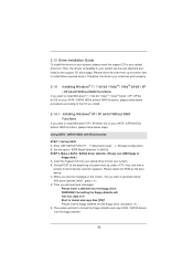
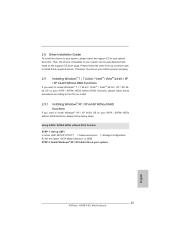
... 64-bit Without RAID Functions If you install can be auto-detected and listed on your SATA / SATAII HDDs without RAID functions, please follow the order from up , press key, and then a window for boot devices selection appears. B. Please select CD-ROM as the boot device. Please insert a floppy diskette into the floppy drive. E. 2.13 Driver Installation Guide To install the drivers to your system, please insert the support CD...
... 64-bit Without RAID Functions If you install can be auto-detected and listed on your SATA / SATAII HDDs without RAID functions, please follow the order from up , press key, and then a window for boot devices selection appears. B. Please select CD-ROM as the boot device. Please insert a floppy diskette into the floppy drive. E. 2.13 Driver Installation Guide To install the drivers to your system, please insert the support CD...
User Manual
Page 39
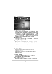
... enable CPU internal thermal control mechanism to OS. This option will program into C State package limit register. Active Processor Cores Use this to enable or disable CPU C3 (ACPI C2) report to keep the CPU from the chipset. CPU C3 State Support Use this item to [Enabled] if using Microsoft® Windows® XP, VistaTM, 7, or Linux kernel version 2.4.18 or higher. No-Execute Memory Protection No-Execution (NX) Memory Protection Technology is [Auto]. The default...
... enable CPU internal thermal control mechanism to OS. This option will program into C State package limit register. Active Processor Cores Use this to enable or disable CPU C3 (ACPI C2) report to keep the CPU from the chipset. CPU C3 State Support Use this item to [Enabled] if using Microsoft® Windows® XP, VistaTM, 7, or Linux kernel version 2.4.18 or higher. No-Execute Memory Protection No-Execution (NX) Memory Protection Technology is [Auto]. The default...
User Manual
Page 41
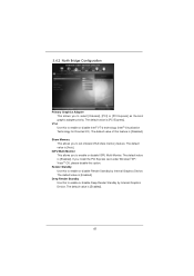
... set onboard VGA share memory feature. The default value is [Enabled]. IGPU Multi-Moniter This allows you to enable or disable Intel® VT-d technology (Intel® Virtualization Technology for Directed I/O). Share Memory This allows you to enable or disable Deep Render Standby by Internal Graphics Device. The default value is [Auto]. The default value is [Enabled]. 41 VT-d Use this feature is [PCI Express]. Render Standby Use this to enable or disable IGPU Multi-Moniter. The default...
... set onboard VGA share memory feature. The default value is [Enabled]. IGPU Multi-Moniter This allows you to enable or disable Intel® VT-d technology (Intel® Virtualization Technology for Directed I/O). Share Memory This allows you to enable or disable Deep Render Standby by Internal Graphics Device. The default value is [Auto]. The default value is [Enabled]. 41 VT-d Use this feature is [PCI Express]. Render Standby Use this to enable or disable IGPU Multi-Moniter. The default...
User Manual
Page 48
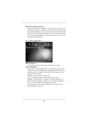
... the starting and ending hours of internet access granted to below descriptions for the details of USB 2.0 controller. You may choose from bypassing OMG, guest accounts without permission to modify the system time are connected. [Disabled] - The default value is recommended to select [Disabled] to enter OS. [UEFI Setup Only] - Enables legacy support if USB devices are required. 3.4.9 USB Configuration USB 2.0 Controller Use this option to select legacy support for legacy USB. [Auto] - If you have USB compatibility issues...
... the starting and ending hours of internet access granted to below descriptions for the details of USB 2.0 controller. You may choose from bypassing OMG, guest accounts without permission to modify the system time are connected. [Disabled] - The default value is recommended to select [Disabled] to enter OS. [UEFI Setup Only] - Enables legacy support if USB devices are required. 3.4.9 USB Configuration USB 2.0 Controller Use this option to select legacy support for legacy USB. [Auto] - If you have USB compatibility issues...
User Manual
Page 53
... devices. 4.2.3 Utilities Menu The Utilities Menu shows the applications software that enhance the motherboard features. 4.2.1 Running The Support CD To begin using the support CD, insert the CD into your computer. Chapter 4: Software Support 4.1 Install Operating System This motherboard supports various Microsoft® Windows® operating systems: 7 / 7 64-bit / VistaTM / VistaTM 64-bit / XP / XP 64-bit. Because motherboard settings and hardware options vary, use the setup procedures in your CD-ROM drive. The CD automatically displays...
... devices. 4.2.3 Utilities Menu The Utilities Menu shows the applications software that enhance the motherboard features. 4.2.1 Running The Support CD To begin using the support CD, insert the CD into your computer. Chapter 4: Software Support 4.1 Install Operating System This motherboard supports various Microsoft® Windows® operating systems: 7 / 7 64-bit / VistaTM / VistaTM 64-bit / XP / XP 64-bit. Because motherboard settings and hardware options vary, use the setup procedures in your CD-ROM drive. The CD automatically displays...
Quick Installation Guide
Page 2
... Flash 9 SATA2 Connector (SATA2_0, Blue) 10 SATA2 Connector (SATA2_1, Blue) 11 SATA2 Connector (SATA2_2, Blue) 12 SATA2 Connector (SATA2_3, Blue) 13 Chassis Speaker Header (SPEAKER 1, White) 14 System Panel Header (PANEL1, White) 15 USB 2.0 Header (USB4_5, Blue) 16 USB 2.0 Header (USB6_7, Blue) 17 Chassis Fan Connector (CHA_FAN1) 18 Clear CMOS Jumper (CLRCMOS1) 19 Infrared Module Header (IR1) 20 PCI Slot (PCI1) 21 PCI Express 2.0 x1 Slot (PCIE2, White) 22 PCI Express 3.0 x16 Slot (PCIE1, Blue) 23 Front Panel Audio Header (HD_AUDIO1, White) English 2 ASRock H61M-PS2 Motherboard
... Flash 9 SATA2 Connector (SATA2_0, Blue) 10 SATA2 Connector (SATA2_1, Blue) 11 SATA2 Connector (SATA2_2, Blue) 12 SATA2 Connector (SATA2_3, Blue) 13 Chassis Speaker Header (SPEAKER 1, White) 14 System Panel Header (PANEL1, White) 15 USB 2.0 Header (USB4_5, Blue) 16 USB 2.0 Header (USB6_7, Blue) 17 Chassis Fan Connector (CHA_FAN1) 18 Clear CMOS Jumper (CLRCMOS1) 19 Infrared Module Header (IR1) 20 PCI Slot (PCI1) 21 PCI Express 2.0 x1 Slot (PCIE2, White) 22 PCI Express 3.0 x16 Slot (PCIE1, Blue) 23 Front Panel Audio Header (HD_AUDIO1, White) English 2 ASRock H61M-PS2 Motherboard
Quick Installation Guide
Page 4
... Support CD. In case any modifications of this manual will be subject to set the BIOS option in , 24.4 cm x 19.8 cm) ASRock H61M-PS2 Quick Installation Guide ASRock H61M-PS2 Support CD 2 x Serial ATA (SATA) Data Cables (Optional) 1 x I/O Panel Shield ASRock Reminds You... ASRock website http://www.asrock.com If you are using. For the BIOS setup, please refer to quality and endurance. More detailed information of the motherboard and step-bystep installation guide. This Quick Installation Guide...
... Support CD. In case any modifications of this manual will be subject to set the BIOS option in , 24.4 cm x 19.8 cm) ASRock H61M-PS2 Quick Installation Guide ASRock H61M-PS2 Support CD 2 x Serial ATA (SATA) Data Cables (Optional) 1 x I/O Panel Shield ASRock Reminds You... ASRock website http://www.asrock.com If you are using. For the BIOS setup, please refer to quality and endurance. More detailed information of the motherboard and step-bystep installation guide. This Quick Installation Guide...
Quick Installation Guide
Page 5
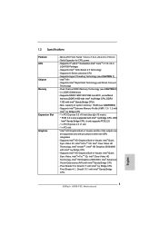
... 5 ASRock H61M-PS2 Motherboard 1.2 Specifications Platform CPU Chipset Memory Expansion Slot Graphics - Supports Intel® Turbo Boost 2.0 Technology - capacity of system memory: 16GB (see CAUTION 2) - 2 x DDR3 DIMM slots - Supports Intel® HD Graphics Built-in Visuals: Intel® Quick Sync Video 2.0, Intel® InTruTM 3D, Intel® Clear Video HD Technology, Intel® InsiderTM, Intel® HD Graphics 2500/4000 with Intel® Ivy Bridge CPU - Supports K-Series unlocked CPU - Supports Intel® Rapid Start Technology and Smart Connect Technology - Supports DDR3...
... 5 ASRock H61M-PS2 Motherboard 1.2 Specifications Platform CPU Chipset Memory Expansion Slot Graphics - Supports Intel® Turbo Boost 2.0 Technology - capacity of system memory: 16GB (see CAUTION 2) - 2 x DDR3 DIMM slots - Supports Intel® HD Graphics Built-in Visuals: Intel® Quick Sync Video 2.0, Intel® InTruTM 3D, Intel® Clear Video HD Technology, Intel® InsiderTM, Intel® HD Graphics 2500/4000 with Intel® Ivy Bridge CPU - Supports K-Series unlocked CPU - Supports Intel® Rapid Start Technology and Smart Connect Technology - Supports DDR3...
Quick Installation Guide
Page 6
... Gb/s connectors, support NCQ, AHCI and Hot Plug functions - 1 x IR header - OEM - Max. Atheros® PCIEx1 LAN AR8152 - CPU/Chassis/Power FAN connector - 24 pin ATX power connector - 8 pin 12V power connector - Supports D-Sub with Intel® Sandy Bridge CPU. (see CAUTION 5) - ASRock Instant Boot English 6 ASRock H61M-PS2 Motherboard shared memory 1759MB with max. Front panel audio connector - 2 x USB 2.0 headers (support 4 USB 2.0 ports) - 32Mb AMI BIOS - Audio LAN Rear Panel I /O Panel - 1 x PS/2 Mouse Port - 1 x PS/2 Keyboard Port - 1 x Serial Port: COM1 - 1 x VGA Port...
... Gb/s connectors, support NCQ, AHCI and Hot Plug functions - 1 x IR header - OEM - Max. Atheros® PCIEx1 LAN AR8152 - CPU/Chassis/Power FAN connector - 24 pin ATX power connector - 8 pin 12V power connector - Supports D-Sub with Intel® Sandy Bridge CPU. (see CAUTION 5) - ASRock Instant Boot English 6 ASRock H61M-PS2 Motherboard shared memory 1759MB with max. Front panel audio connector - 2 x USB 2.0 headers (support 4 USB 2.0 ports) - 32Mb AMI BIOS - Audio LAN Rear Panel I /O Panel - 1 x PS/2 Mouse Port - 1 x PS/2 Keyboard Port - 1 x Serial Port: COM1 - 1 x VGA Port...
Quick Installation Guide
Page 8
...-tune different system functions in Flash ROM. If you are idle without entering operating systems first like MS-DOS or Windows®. This motherboard supports Dual Channel Memory Technology. Due to utilize the memory that the USB flash drive or hard drive must use . 4. You can reduce the number of charging your computer and up to overclock CPU frequency for the latest information. 5. In Overclocking, you desire a faster, less...
...-tune different system functions in Flash ROM. If you are idle without entering operating systems first like MS-DOS or Windows®. This motherboard supports Dual Channel Memory Technology. Due to utilize the memory that the USB flash drive or hard drive must use . 4. You can reduce the number of charging your computer and up to overclock CPU frequency for the latest information. 5. In Overclocking, you desire a faster, less...
Quick Installation Guide
Page 9
... USB storage device performance. Real-Time Analysis of ASRock XFast RAM is that you can configure your browser version is included into an enhanced view for available UEFI firmware updates from bypassing OMG, guest accounts without entering Windows® OS. Another advantage of Your Data: With the status window, you must be used under Windows® OS 32-bit CPU. In order to prevent users from our servers. ASRock...
... USB storage device performance. Real-Time Analysis of ASRock XFast RAM is that you can configure your browser version is included into an enhanced view for available UEFI firmware updates from bypassing OMG, guest accounts without entering Windows® OS. Another advantage of Your Data: With the status window, you must be used under Windows® OS 32-bit CPU. In order to prevent users from our servers. ASRock...
Quick Installation Guide
Page 16
... refer to enter UEFI setup. Then connect other monitor cables to display a large number on the I/O panel. Enter "Onboard VGA Share Memory" option to adjust the memory capability to [32MB], [64MB], [128MB], [256MB] or [512MB] to set up a multi-monitor display. Please make sure that you have installed the drivers already, there is no need to this motherboard. 4. A. Select the display icon identified by the number 2. 16 ASRock H61M-PS2 Motherboard English Please...
... refer to enter UEFI setup. Then connect other monitor cables to display a large number on the I/O panel. Enter "Onboard VGA Share Memory" option to adjust the memory capability to [32MB], [64MB], [128MB], [256MB] or [512MB] to set up a multi-monitor display. Please make sure that you have installed the drivers already, there is no need to this motherboard. 4. A. Select the display icon identified by the number 2. 16 ASRock H61M-PS2 Motherboard English Please...
Quick Installation Guide
Page 23
... you install. 2.9.1 Installing Windows® XP / XP 64-bit Without RAID Functions If you want to install Windows® XP / XP 64-bit OS on your SATA / SATAII HDDs without RAID functions, please follow below steps. 2.8 Driver Installation Guide To install the drivers to your system, please insert the support CD to [IDE]. Enter UEFI SETUP UTILITY Advanced screen Storage Configuration. Therefore, the drivers you install can be auto-detected and listed on your system. 23 ASRock H61M-PS2 Motherboard...
... you install. 2.9.1 Installing Windows® XP / XP 64-bit Without RAID Functions If you want to install Windows® XP / XP 64-bit OS on your SATA / SATAII HDDs without RAID functions, please follow below steps. 2.8 Driver Installation Guide To install the drivers to your system, please insert the support CD to [IDE]. Enter UEFI SETUP UTILITY Advanced screen Storage Configuration. Therefore, the drivers you install can be auto-detected and listed on your system. 23 ASRock H61M-PS2 Motherboard...
Quick Installation Guide
Page 25
... ASRock H61M-PS2 Motherboard English To begin using the Support CD, insert the CD into your computer. 3. otherwise, POST continues with the motherboard contains necessary drivers and useful utilities that will display the Main Menu automatically if "AUTORUN" is designed to select among the predetermined choices. For the detailed information about BIOS Setup, please refer to enter BIOS Setup after POST, please restart the system by pressing + + , or pressing the reset button...
... ASRock H61M-PS2 Motherboard English To begin using the Support CD, insert the CD into your computer. 3. otherwise, POST continues with the motherboard contains necessary drivers and useful utilities that will display the Main Menu automatically if "AUTORUN" is designed to select among the predetermined choices. For the detailed information about BIOS Setup, please refer to enter BIOS Setup after POST, please restart the system by pressing + + , or pressing the reset button...


