User Manual
Page 11
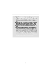
...® Windows® XP / XP 64-bit. 17. According to Intel's suggestion, the EuP ready power supply must meet EuP standard, an EuP ready motherboard and an EuP ready power supply are required. According to spray thermal grease between the CPU and the heatsink when you checking with the power...the system, please check if the CPU fan on the motherboard functions properly and unplug the power cord, then plug it back again. ASRock XFast RAM is not supported by European Union to adopt three different CPU cooler types, Socket LGA 775, LGA 1155 and LGA 1156. Please be noticed that not all ...
...® Windows® XP / XP 64-bit. 17. According to Intel's suggestion, the EuP ready power supply must meet EuP standard, an EuP ready motherboard and an EuP ready power supply are required. According to spray thermal grease between the CPU and the heatsink when you checking with the power...the system, please check if the CPU fan on the motherboard functions properly and unplug the power cord, then plug it back again. ASRock XFast RAM is not supported by European Union to adopt three different CPU cooler types, Socket LGA 775, LGA 1155 and LGA 1156. Please be noticed that not all ...
User Manual
Page 12
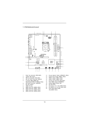
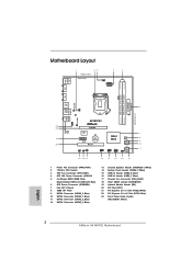
1.3 Motherboard Layout 1 23 19.8cm (7.8 in) 4 5 Designed in Taipei CPU_FAN1 ATX12V1 PS2 Mouse PS2 Keyboard COM1 DDR3 DDR3_A1 (64 bit, 240-pin module...: B: USB3 RJ-45 LAN PHY 1 HD_AUDIO1 Fast USB X Top: LINE IN Center: FRONT Bottom: MIC IN H61M-PS2 ErP/EuP Ready 23 22 AUDIO CODEC 21 20 PCIE1 Super I/O PCIE2 RoHS CMOS Battery PCI1 IR1 1 CHA_FAN1 CLRCMOS1 ...SPEAKER1 1 SATA2_3 7 8 9 10 11 19 18 17 16 15 14 13 12 1 Power Fan Connector (PWR_FAN1) 2 1155-Pin CPU Socket 3 CPU Fan Connector (CPU_FAN1) 4 ATX 12V Power Connector (ATX12V1 5 2 x 240-pin DDR3 DIMM Slots (Dual ...
1.3 Motherboard Layout 1 23 19.8cm (7.8 in) 4 5 Designed in Taipei CPU_FAN1 ATX12V1 PS2 Mouse PS2 Keyboard COM1 DDR3 DDR3_A1 (64 bit, 240-pin module...: B: USB3 RJ-45 LAN PHY 1 HD_AUDIO1 Fast USB X Top: LINE IN Center: FRONT Bottom: MIC IN H61M-PS2 ErP/EuP Ready 23 22 AUDIO CODEC 21 20 PCIE1 Super I/O PCIE2 RoHS CMOS Battery PCI1 IR1 1 CHA_FAN1 CLRCMOS1 ...SPEAKER1 1 SATA2_3 7 8 9 10 11 19 18 17 16 15 14 13 12 1 Power Fan Connector (PWR_FAN1) 2 1155-Pin CPU Socket 3 CPU Fan Connector (CPU_FAN1) 4 ATX 12V Power Connector (ATX12V1 5 2 x 240-pin DDR3 DIMM Slots (Dual ...
User Manual
Page 15
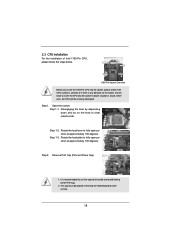
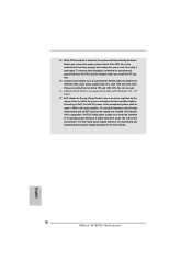
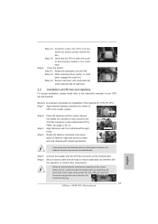
Step 2. Otherwise, the CPU will be placed if returning the motherboard for after service. 15 Disengaging the lever by depressing down and out on the socket. This cap must be seriously damaged. Step 1. Rotate the load lever to clear retention tab. Remove PnP Cap (Pick and Place Cap...there is found. 2.3 CPU Installation For the installation of Intel 1155-Pin CPU, please follow the steps below. Load Plate Load Lever Contact Array Socket Body 1155-Pin Socket Overview Before you insert the 1155-Pin CPU into the socket if above situation is any bent pin on the hook to...
Step 2. Otherwise, the CPU will be placed if returning the motherboard for after service. 15 Disengaging the lever by depressing down and out on the socket. This cap must be seriously damaged. Step 1. Rotate the load lever to clear retention tab. Remove PnP Cap (Pick and Place Cap...there is found. 2.3 CPU Installation For the installation of Intel 1155-Pin CPU, please follow the steps below. Load Plate Load Lever Contact Array Socket Body 1155-Pin Socket Overview Before you insert the 1155-Pin CPU into the socket if above situation is any bent pin on the hook to...
User Manual
Page 17
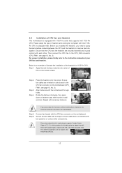
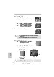
... 2. Step 5. Apply thermal interface material onto center of IHS on the motherboard (CPU_ FAN1, see page 12, No. 3). Ensure fan cables are oriented on side closest to adopt three different CPU cooler types, Socket LGA 775, LGA 1155 and LGA 1156. Step 6. Then connect the CPU fan to improve heat... thermal interface material between the CPU and the heatsink to the CPU_FAN connector (CPU_FAN1, see page 12, No. 3). Fan cables on the motherboard. 2.4 Installation of the heatsink for Socket LGA 1155/1156 CPU fan. 17 Connect fan header with tie-wrap to dissipate heat.
... 2. Step 5. Apply thermal interface material onto center of IHS on the motherboard (CPU_ FAN1, see page 12, No. 3). Ensure fan cables are oriented on side closest to adopt three different CPU cooler types, Socket LGA 775, LGA 1155 and LGA 1156. Step 6. Then connect the CPU fan to improve heat... thermal interface material between the CPU and the heatsink to the CPU_FAN connector (CPU_FAN1, see page 12, No. 3). Fan cables on the motherboard. 2.4 Installation of the heatsink for Socket LGA 1155/1156 CPU fan. 17 Connect fan header with tie-wrap to dissipate heat.
Quick Installation Guide
Page 2
... USB2 Top: B: USB3 RJ-45 LAN PHY 1 HD_AUDIO1 Fast USB X Top: LINE IN Center: FRONT Bottom: MIC IN H61M-PS2 ErP/EuP Ready 23 22 AUDIO CODEC 21 20 PCIE1 Super I/O PCIE2 RoHS CMOS Battery PCI1 IR1 1 CHA_FAN1 CLRCMOS1 1 USB6_7 ... SATA2_1 SATA2_2 SPEAKER1 1 SATA2_3 7 8 9 10 11 19 18 17 16 15 14 13 12 1 Power Fan Connector (PWR_FAN1) 2 1155-Pin CPU Socket 3 CPU Fan Connector (CPU_FAN1) 4 ATX 12V Power Connector (ATX12V1 5 2 x 240-pin DDR3 DIMM Slots (Dual Channel: DDR3_A1,...Slot (PCIE1, Blue) 23 Front Panel Audio Header (HD_AUDIO1, White) English 2 ASRock H61M-PS2 Motherboard
... USB2 Top: B: USB3 RJ-45 LAN PHY 1 HD_AUDIO1 Fast USB X Top: LINE IN Center: FRONT Bottom: MIC IN H61M-PS2 ErP/EuP Ready 23 22 AUDIO CODEC 21 20 PCIE1 Super I/O PCIE2 RoHS CMOS Battery PCI1 IR1 1 CHA_FAN1 CLRCMOS1 1 USB6_7 ... SATA2_1 SATA2_2 SPEAKER1 1 SATA2_3 7 8 9 10 11 19 18 17 16 15 14 13 12 1 Power Fan Connector (PWR_FAN1) 2 1155-Pin CPU Socket 3 CPU Fan Connector (CPU_FAN1) 4 ATX 12V Power Connector (ATX12V1 5 2 x 240-pin DDR3 DIMM Slots (Dual Channel: DDR3_A1,...Slot (PCIE1, Blue) 23 Front Panel Audio Header (HD_AUDIO1, White) English 2 ASRock H61M-PS2 Motherboard
Quick Installation Guide
Page 10
... cord, then plug it back again. Combo Cooler Option (C.C.O.) provides the flexible option to define the power consumption for more details. 10 ASRock H61M-PS2 Motherboard English 14. Please be noticed that not all the 775 and 1156 CPU Fan can be under 100 mA current consumption. Before you checking with... EuP, the total AC power of 5v standby power efficiency is not supported by European Union to adopt three different CPU cooler types, Socket LGA 775, LGA 1155 and LGA 1156.
... cord, then plug it back again. Combo Cooler Option (C.C.O.) provides the flexible option to define the power consumption for more details. 10 ASRock H61M-PS2 Motherboard English 14. Please be noticed that not all the 775 and 1156 CPU Fan can be under 100 mA current consumption. Before you checking with... EuP, the total AC power of 5v standby power efficiency is not supported by European Union to adopt three different CPU cooler types, Socket LGA 775, LGA 1155 and LGA 1156.
Quick Installation Guide
Page 11
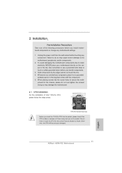
... Array Load Lever Socket Body 1155-Pin Socket Overview Before you install motherboard components or change any component. Installation Pre-installation Precautions Take note of Intel 1155-Pin CPU, please...motherboard directly on the socket. Whenever you handle components. 3. 2. Also remember to do so may damage the motherboard. 2.1 CPU Installation For the installation of the following precautions before you uninstall any bent pin on the carpet or the like. To avoid damaging the motherboard components due to secure the moth- English 11 ASRock H61M-PS2 Motherboard...
... Array Load Lever Socket Body 1155-Pin Socket Overview Before you install motherboard components or change any component. Installation Pre-installation Precautions Take note of Intel 1155-Pin CPU, please...motherboard directly on the socket. Whenever you handle components. 3. 2. Also remember to do so may damage the motherboard. 2.1 CPU Installation For the installation of the following precautions before you uninstall any bent pin on the carpet or the like. To avoid damaging the motherboard components due to secure the moth- English 11 ASRock H61M-PS2 Motherboard...
Quick Installation Guide
Page 12
... 1-1. Step 1-3. Step 3. Insert the 1155-Pin CPU: Step 3-1. Orient the CPU with the two alignment keys of the socket. 12 ASRock H61M-PS2 Motherboard It is recommended to use the cap tab to fully open position at approximately 100 degrees. Hold the CPU by depressing down ... with black lines. Rotate the load lever to clear retention tab. orientation key notch alignment key Pin1 Pin1 orientation key notch 1155-Pin CPU alignment key 1155-Pin Socket For proper inserting, please ensure to match the two orientation key notches of the CPU with IHS (Integrated Heat Sink) up...
... 1-1. Step 1-3. Step 3. Insert the 1155-Pin CPU: Step 3-1. Orient the CPU with the two alignment keys of the socket. 12 ASRock H61M-PS2 Motherboard It is recommended to use the cap tab to fully open position at approximately 100 degrees. Hold the CPU by depressing down ... with black lines. Rotate the load lever to clear retention tab. orientation key notch alignment key Pin1 Pin1 orientation key notch 1155-Pin CPU alignment key 1155-Pin Socket For proper inserting, please ensure to match the two orientation key notches of the CPU with IHS (Integrated Heat Sink) up...
Quick Installation Guide
Page 13
... on the socket surface. Close the socket: Step 4-1. Step 1. Step 3. Apply Thermal Interface Material Step 2. Carefully place the CPU into the socket by using a purely vertical motion. Secure load lever with the motherboard throughholes. Below is within the socket and properly mated to illustrate the installation of the heatsink for Socket LGA 1155/1156 CPU fan. 13 ASRock H61M-PS2 Motherboard
... on the socket surface. Close the socket: Step 4-1. Step 1. Step 3. Apply Thermal Interface Material Step 2. Carefully place the CPU into the socket by using a purely vertical motion. Secure load lever with the motherboard throughholes. Below is within the socket and properly mated to illustrate the installation of the heatsink for Socket LGA 1155/1156 CPU fan. 13 ASRock H61M-PS2 Motherboard


