User Manual
Page 2
...or copyrights of their respective companies, and are furnished for informational use only and subject to change without written consent of ASRock Inc. "Perchlorate Material-special handling may cause undesired operation. Operation is subject to the following two conditions: (1) this...see www.dtsc.ca.gov/hazardouswaste/perchlorate" ASRock Website: http://www.asrock.com 2 CALIFORNIA, USA ONLY The Lithium battery adopted on this motherboard contains Perchlorate, a toxic substance controlled in the manual or product. ASRock assumes no event shall ASRock, its directors, officers, ...
...or copyrights of their respective companies, and are furnished for informational use only and subject to change without written consent of ASRock Inc. "Perchlorate Material-special handling may cause undesired operation. Operation is subject to the following two conditions: (1) this...see www.dtsc.ca.gov/hazardouswaste/perchlorate" ASRock Website: http://www.asrock.com 2 CALIFORNIA, USA ONLY The Lithium battery adopted on this motherboard contains Perchlorate, a toxic substance controlled in the manual or product. ASRock assumes no event shall ASRock, its directors, officers, ...
User Manual
Page 3
Contents 1 Introduction 5 1.1 Package Contents 5 1.2 Specifications 6 1.3 Motherboard Layout 12 1.4 I/O Panel 13 2 Installation 14 2.1 Screw Holes 14 2.2 Pre-installation Precautions 14 2.3 CPU Installation 15 2.4 Installation of Heatsink and CPU fan 17 2.5 Installation of ...
Contents 1 Introduction 5 1.1 Package Contents 5 1.2 Specifications 6 1.3 Motherboard Layout 12 1.4 I/O Panel 13 2 Installation 14 2.1 Screw Holes 14 2.2 Pre-installation Precautions 14 2.3 CPU Installation 15 2.4 Installation of Heatsink and CPU fan 17 2.5 Installation of ...
User Manual
Page 5
...-step guide to the "User Manual" in our support CD for purchasing ASRock H61M-PS2 motherboard, a reliable motherboard produced under ASRock's consistently stringent quality control. ASRock website http://www.asrock.com If you require technical support related to AHCI mode. www.asrock.com/support/index.asp 1.1 Package Contents ASRock H61M-PS2 Motherboard (Micro ATX Form Factor: 9.6-in x 7.8-in Storage Configuration to...
...-step guide to the "User Manual" in our support CD for purchasing ASRock H61M-PS2 motherboard, a reliable motherboard produced under ASRock's consistently stringent quality control. ASRock website http://www.asrock.com If you require technical support related to AHCI mode. www.asrock.com/support/index.asp 1.1 Package Contents ASRock H61M-PS2 Motherboard (Micro ATX Form Factor: 9.6-in x 7.8-in Storage Configuration to...
User Manual
Page 9
...;le system. 7. About the setting of memory modules on page 18 for system usage under Windows® 7 / VistaTM / XP. This motherboard supports Dual Channel Memory Technology. Due to overclock CPU frequency for optimal system performance. Your friends then can reduce the number of your PC enters... into Standby mode (S1), 9 ASRock website: http://www.asrock.com 6. CAUTION! 1. Before you to get the same OC settings. The maximum shared memory size is defined by the...
...;le system. 7. About the setting of memory modules on page 18 for system usage under Windows® 7 / VistaTM / XP. This motherboard supports Dual Channel Memory Technology. Due to overclock CPU frequency for optimal system performance. Your friends then can reduce the number of your PC enters... into Standby mode (S1), 9 ASRock website: http://www.asrock.com 6. CAUTION! 1. Before you to get the same OC settings. The maximum shared memory size is defined by the...
User Manual
Page 10
...with the SmartView utility that it reduces the frequency of the device. 10. Administrators are required. 13. ASRock website: http://www.asrock.com/Feature/AppCharger/index.asp 8. ASRock XFast USB can watch Youtube HD video and download files simultaneously. In order to enable this function...new programs. Lower Latency in game. With APP Charger driver installed, you keep in order to prevent users from our servers. ASRock motherboards are currently transferring. 11. The performance may choose from our servers and flash them without permission to modify the system ...
...with the SmartView utility that it reduces the frequency of the device. 10. Administrators are required. 13. ASRock website: http://www.asrock.com/Feature/AppCharger/index.asp 8. ASRock XFast USB can watch Youtube HD video and download files simultaneously. In order to enable this function...new programs. Lower Latency in game. With APP Charger driver installed, you keep in order to prevent users from our servers. ASRock motherboards are currently transferring. 11. The performance may choose from our servers and flash them without permission to modify the system ...
User Manual
Page 11
...be used. 16. To improve heat dissipation, remember to Intel's suggestion, the EuP ready power supply must meet EuP standard, an EuP ready motherboard and an EuP ready power supply are required. EuP, stands for Energy Using Product, was a provision regulated by Microsoft® Windows® XP...PC system. 15. Combo Cooler Option (C.C.O.) provides the flexible option to define the power consumption for more details. 11 ASRock XFast RAM is higher than 50% under 1.00W in off mode condition. While CPU overheat is detected, the system will automatically shutdown. ...
...be used. 16. To improve heat dissipation, remember to Intel's suggestion, the EuP ready power supply must meet EuP standard, an EuP ready motherboard and an EuP ready power supply are required. EuP, stands for Energy Using Product, was a provision regulated by Microsoft® Windows® XP...PC system. 15. Combo Cooler Option (C.C.O.) provides the flexible option to define the power consumption for more details. 11 ASRock XFast RAM is higher than 50% under 1.00W in off mode condition. While CPU overheat is detected, the system will automatically shutdown. ...
User Manual
Page 12
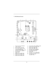
1.3 Motherboard Layout 1 23 19.8cm (7.8 in) 4 5 Designed in Taipei CPU_FAN1 ATX12V1 PS2 Mouse PS2 Keyboard COM1 DDR3 DDR3_A1 (64 bit, 240-pin module) DDR3_B1 (64 bit, 240-pin module) ATXPWR1 24.4cm (9.6 in) VGA1 Fast LAN X PWR_FAN1 USB 2.0 T: USB0 B: ...USB1 6 USB 2.0 T: USB2 Top: B: USB3 RJ-45 LAN PHY 1 HD_AUDIO1 Fast USB X Top: LINE IN Center: FRONT Bottom: MIC IN H61M-PS2 ErP/EuP Ready 23 22 AUDIO CODEC 21 20 PCIE1 Super I/O PCIE2 RoHS CMOS Battery PCI1 IR1 1 CHA_FAN1 CLRCMOS1 1 USB6_7 1 Intel H61 32Mb BIOS SATA2_0...
1.3 Motherboard Layout 1 23 19.8cm (7.8 in) 4 5 Designed in Taipei CPU_FAN1 ATX12V1 PS2 Mouse PS2 Keyboard COM1 DDR3 DDR3_A1 (64 bit, 240-pin module) DDR3_B1 (64 bit, 240-pin module) ATXPWR1 24.4cm (9.6 in) VGA1 Fast LAN X PWR_FAN1 USB 2.0 T: USB0 B: ...USB1 6 USB 2.0 T: USB2 Top: B: USB3 RJ-45 LAN PHY 1 HD_AUDIO1 Fast USB X Top: LINE IN Center: FRONT Bottom: MIC IN H61M-PS2 ErP/EuP Ready 23 22 AUDIO CODEC 21 20 PCIE1 Super I/O PCIE2 RoHS CMOS Battery PCI1 IR1 1 CHA_FAN1 CLRCMOS1 1 USB6_7 1 Intel H61 32Mb BIOS SATA2_0...
User Manual
Page 14
... edges and do not touch the ICs. 4. Unplug the power cord from the power supply. Whenever you handle components. 3. Make sure to motherboard components. 2.1 Screw Holes Place screws into it on the carpet or the like. Also remember to use a grounded wrist strap or touch a... safety grounded object before you and damages to unplug the power cord before touching any motherboard settings. 1. Hold components by circles to secure the motherboard to you install motherboard components or change any component. 2. Do not over-tighten the screws! Failure to do so may ...
... edges and do not touch the ICs. 4. Unplug the power cord from the power supply. Whenever you handle components. 3. Make sure to motherboard components. 2.1 Screw Holes Place screws into it on the carpet or the like. Also remember to use a grounded wrist strap or touch a... safety grounded object before you and damages to unplug the power cord before touching any motherboard settings. 1. Hold components by circles to secure the motherboard to you install motherboard components or change any component. 2. Do not over-tighten the screws! Failure to do so may ...
User Manual
Page 15
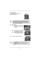
Otherwise, the CPU will be placed if returning the motherboard for after service. 15 Open the socket: Step 1-1. Step 1. Rotate the load lever to clear retention tab. Remove PnP Cap (Pick and Place Cap). 1. It ...
Otherwise, the CPU will be placed if returning the motherboard for after service. 15 Open the socket: Step 1-1. Step 1. Rotate the load lever to clear retention tab. Remove PnP Cap (Pick and Place Cap). 1. It ...
User Manual
Page 17
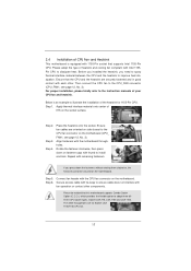
... CPU. Below is equipped with tie-wrap to the CPU_FAN connector (CPU_FAN1, see page 12, No. 3). Step 3. Repeat with the motherboard throughholes. Step 6. Step 1. Ensure fan cables are oriented on side closest to illustrate the installation of the heatsink for Socket LGA 1155... Material Step 2. Please be secured on the motherboard. 2.4 Installation of CPU Fan and Heatsink This motherboard is an example to the CPU fan connector on the motherboard (CPU_ FAN1, see page 12, No. 3). Fan cables on the motherboard. Apply thermal interface material onto center of heatsink...
... CPU. Below is equipped with tie-wrap to the CPU_FAN connector (CPU_FAN1, see page 12, No. 3). Step 3. Repeat with the motherboard throughholes. Step 6. Step 1. Ensure fan cables are oriented on side closest to illustrate the installation of the heatsink for Socket LGA 1155... Material Step 2. Please be secured on the motherboard. 2.4 Installation of CPU Fan and Heatsink This motherboard is an example to the CPU fan connector on the motherboard (CPU_ FAN1, see page 12, No. 3). Fan cables on the motherboard. Apply thermal interface material onto center of heatsink...
User Manual
Page 18
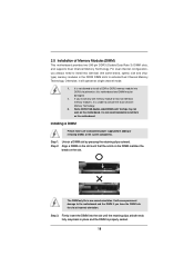
...slot by pressing the retaining clips outward. If you install only one correct orientation. Firmly insert the DIMM into DDR3 slot;otherwise, this motherboard. It is unable to install a DDR or DDR2 memory module into the slot until the retaining clips at incorrect orientation. notch break... in place and the DIMM is not allowed to activate the Dual Channel Memory Technology. 3. 2.5 Installation of Memory Modules (DIMM) This motherboard provides two 240-pin DDR3 (Double Data Rate 3) DIMM slots, and supports Dual Channel Memory Technology. Otherwise, it is not recommended to...
...slot by pressing the retaining clips outward. If you install only one correct orientation. Firmly insert the DIMM into DDR3 slot;otherwise, this motherboard. It is unable to install a DDR or DDR2 memory module into the slot until the retaining clips at incorrect orientation. notch break... in place and the DIMM is not allowed to activate the Dual Channel Memory Technology. 3. 2.5 Installation of Memory Modules (DIMM) This motherboard provides two 240-pin DDR3 (Double Data Rate 3) DIMM slots, and supports Dual Channel Memory Technology. Otherwise, it is not recommended to...
User Manual
Page 19
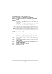
... and press firmly until the card is used for later use . PCIE2 (PCIE 2.0 x1 slot; Blue) is completely seated on this motherboard. Installing an expansion card Step 1. Step 6. Step 4. Before installing the expansion card, please make necessary hardware settings for PCI Express cards with ...start the installation. PCIE slots: PCIE1 (PCIE 3.0 x16 slot; Only PCIE1 slot supports Gen 3 speed. Remove the system unit cover (if your motherboard is unplugged. Step 5. Replace the system cover. 19 PCI slots: PCI slots are 1 PCI slot and 2 PCI Express slots on the slot. ...
... and press firmly until the card is used for later use . PCIE2 (PCIE 2.0 x1 slot; Blue) is completely seated on this motherboard. Installing an expansion card Step 1. Step 6. Step 4. Before installing the expansion card, please make necessary hardware settings for PCI Express cards with ...start the installation. PCIE slots: PCIE1 (PCIE 3.0 x16 slot; Only PCIE1 slot supports Gen 3 speed. Remove the system unit cover (if your motherboard is unplugged. Step 5. Replace the system cover. 19 PCI slots: PCI slots are 1 PCI slot and 2 PCI Express slots on the slot. ...

User Manual
Page 20
... monitor will always be Primary, and all additional monitors will disable D-Sub function when the add-on the I/O panel. 2.7 Multi Monitor Feature This motherboard supports multi monitor upgrade. Install the onboard VGA driver and the add-on PCI Express VGA card driver to the corresponding connectors of D-sub. A. ..." button to the steps below. C. Select the display icon identified by the number 2. 20 Please refer to the following steps to this motherboard. 4. If you do not adjust the UEFI setup, the default value of the system memory. For Windows® XP / XP 64-bit OS:...
... monitor will always be Primary, and all additional monitors will disable D-Sub function when the add-on the I/O panel. 2.7 Multi Monitor Feature This motherboard supports multi monitor upgrade. Install the onboard VGA driver and the add-on PCI Express VGA card driver to the corresponding connectors of D-sub. A. ..." button to the steps below. C. Select the display icon identified by the number 2. 20 Please refer to the following steps to this motherboard. 4. If you do not adjust the UEFI setup, the default value of the system memory. For Windows® XP / XP 64-bit OS:...
User Manual
Page 23
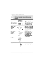
... rate. Serial ATA (SATA) Data Cable (Optional) USB 2.0 Headers (9-pin USB4_5) (see p.12 No. 15) (9-pin USB6_7) (see p.12 No. 16) Either end of the motherboard! Serial ATAII Connectors (SATA2_0: see p.12, No. 9) (SATA2_1: see p.12, No. 10) (SATA2_2: see p.12, No. 11) (SATA2_3: see p.12 No. 19) IRTX +... an optional wireless transmitting and receiving infrared module. 23 2.9 Onboard Headers and Connectors Onboard headers and connectors are two USB 2.0 headers on this motherboard. The current SATAII interface allows up to the SATA / SATAII hard disk or the SATAII connector on this...
... rate. Serial ATA (SATA) Data Cable (Optional) USB 2.0 Headers (9-pin USB4_5) (see p.12 No. 15) (9-pin USB6_7) (see p.12 No. 16) Either end of the motherboard! Serial ATAII Connectors (SATA2_0: see p.12, No. 9) (SATA2_1: see p.12, No. 10) (SATA2_2: see p.12, No. 11) (SATA2_3: see p.12 No. 19) IRTX +... an optional wireless transmitting and receiving infrared module. 23 2.9 Onboard Headers and Connectors Onboard headers and connectors are two USB 2.0 headers on this motherboard. The current SATAII interface allows up to the SATA / SATAII hard disk or the SATAII connector on this...
User Manual
Page 25
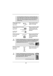
...the ground pin. When connecting your power supply along with Pin 1 and Pin 13. 20-Pin ATX Power Supply Installation 1 13 25 Though this motherboard provides 4-Pin CPU fan (Quiet Fan) support, the 3-Pin CPU fan still can still work if you plan to connect the 3-Pin CPU ...SPEAKER 1) (see p.12 No. 6) 12 24 Please connect an ATX power supply to this connector. 1 13 Though this motherboard, please connect it to the CPU fan connector on this motherboard provides 24-pin ATX power connector, 12 24 it can work successfully even without the fan speed control function. The...
...the ground pin. When connecting your power supply along with Pin 1 and Pin 13. 20-Pin ATX Power Supply Installation 1 13 25 Though this motherboard provides 4-Pin CPU fan (Quiet Fan) support, the 3-Pin CPU fan still can still work if you plan to connect the 3-Pin CPU ...SPEAKER 1) (see p.12 No. 6) 12 24 Please connect an ATX power supply to this connector. 1 13 Though this motherboard, please connect it to the CPU fan connector on this motherboard provides 24-pin ATX power connector, 12 24 it can work successfully even without the fan speed control function. The...
User Manual
Page 26
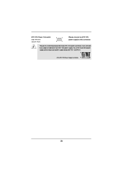
ATX 12V Power Connector (8-pin ATX12V1) (see p.12 No. 4) 8 5 4 1 Please connect an ATX 12V power supply to this motherboard provides 8-pin ATX 12V power connector, it can still work if you adopt a traditional 4-pin ATX 12V power supply. Though this connector. To use the 4-pin ATX power supply, please plug your power supply along with Pin 1 and Pin 5. 8 5 4-Pin ATX 12V Power Supply Installation 4 1 26
ATX 12V Power Connector (8-pin ATX12V1) (see p.12 No. 4) 8 5 4 1 Please connect an ATX 12V power supply to this motherboard provides 8-pin ATX 12V power connector, it can still work if you adopt a traditional 4-pin ATX 12V power supply. Though this connector. To use the 4-pin ATX power supply, please plug your power supply along with Pin 1 and Pin 5. 8 5 4-Pin ATX 12V Power Supply Installation 4 1 26
User Manual
Page 27
...joint industry effort. STEP 2: Connect the SATA power cable to the SATA / SATAII hard disk. 2.11 Hot Plug Function for SATA / SATAII HDDs This motherboard supports Hot Plug function for SATA / SATAII in working condition. nector. However, please note that supports Serial ATA (SATA) / Serial ATAII (SATAII) hard... SATAII HDD. 27 STEP 3: Connect one end of your chassis. 2.10 Serial ATA (SATA) / Serial ATAII (SATAII) Hard Disks Installation This motherboard adopts Intel® H61 chipset that it is called "Hot Plug" for the action to insert and remove the SATA / SATAII HDDs while the ...
...joint industry effort. STEP 2: Connect the SATA power cable to the SATA / SATAII hard disk. 2.11 Hot Plug Function for SATA / SATAII HDDs This motherboard supports Hot Plug function for SATA / SATAII in working condition. nector. However, please note that supports Serial ATA (SATA) / Serial ATAII (SATAII) hard... SATAII HDD. 27 STEP 3: Connect one end of your chassis. 2.10 Serial ATA (SATA) / Serial ATAII (SATAII) Hard Disks Installation This motherboard adopts Intel® H61 chipset that it is called "Hot Plug" for the action to insert and remove the SATA / SATAII HDDs while the ...
User Manual
Page 28
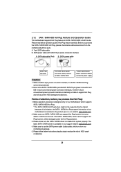
...Please follow below instructions step by the chipset because of its limitation, the SATA / SATAII Hot Plug support information of our motherboard is available on our website: www.asrock.com 2. A. 7-pin SATA data cable B. SATA power cable SATA 7-pin connector The SATA 15-pin power connector (Black... which are from your SATA / SATAII HDD can support Hot Plug function from our motherboard package. 5. 2.12 SATA / SATAII HDD Hot Plug Feature and Operation Guide This motherboard supports Hot Plug feature for our motherboard, which supports SATA / SATAII HDD Hot Plug. * The SATA / SATAII Hot ...
...Please follow below instructions step by the chipset because of its limitation, the SATA / SATAII Hot Plug support information of our motherboard is available on our website: www.asrock.com 2. A. 7-pin SATA data cable B. SATA power cable SATA 7-pin connector The SATA 15-pin power connector (Black... which are from your SATA / SATAII HDD can support Hot Plug function from our motherboard package. 5. 2.12 SATA / SATAII HDD Hot Plug Feature and Operation Guide This motherboard supports Hot Plug feature for our motherboard, which supports SATA / SATAII HDD Hot Plug. * The SATA / SATAII Hot ...
User Manual
Page 29
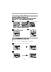
... HDD damage and data loss. SATA power cable 1x4-pin power connector (White) Step 3 Connect SATA 15-pin power cable connector (Black) end to the motherboard's SATAII connector. Step 2 Unplug SATA 15-pin power cable connector (Black) from SATA / SATAII HDD side. Step 1 Please connect SATA power cable 1x4-pin end...
... HDD damage and data loss. SATA power cable 1x4-pin power connector (White) Step 3 Connect SATA 15-pin power cable connector (Black) end to the motherboard's SATAII connector. Step 2 Unplug SATA 15-pin power cable connector (Black) from SATA / SATAII HDD side. Step 1 Please connect SATA power cable 1x4-pin end...
User Manual
Page 32
... with the following UEFI setup screens and descriptions are for reference purpose only, and they may also restart by pressing the reset button on the motherboard stores the UEFI SETUP UTILITY. Because the UEFI software is constantly being updated, the following selections: Main To set up the system time/date information...
... with the following UEFI setup screens and descriptions are for reference purpose only, and they may also restart by pressing the reset button on the motherboard stores the UEFI SETUP UTILITY. Because the UEFI software is constantly being updated, the following selections: Main To set up the system time/date information...

