
User Manual
Page 3
... Contents 1 1.2 Specifications 2 1.3 Motherboard Layout 6 1.4 I/O Panel 8 Chapter 2 Installation 9 2.1 Installing the CPU 10 2.2 Installing the CPU Fan and Heatsink 13 2.3 Installing Memory Modules (DIMM) 14 2.4 Expansion Slots (PCI Express Slots) 16 2.5 Jumpers Setup 17 2.6 Onboard Headers and Connectors 18 Chapter 3 Software and Utilities Operation 22 3.1 Installing Drivers 22 3.2 ASRock Motherboard Utility (A-Tuning) 23 3.2.1 Installing ASRock Motherboard Utility (A-Tuning) 23 3.2.2 Using ASRock Motherboard Utility (A-Tuning) 23 3.3 ASRock Live Update & APP...
... Contents 1 1.2 Specifications 2 1.3 Motherboard Layout 6 1.4 I/O Panel 8 Chapter 2 Installation 9 2.1 Installing the CPU 10 2.2 Installing the CPU Fan and Heatsink 13 2.3 Installing Memory Modules (DIMM) 14 2.4 Expansion Slots (PCI Express Slots) 16 2.5 Jumpers Setup 17 2.6 Onboard Headers and Connectors 18 Chapter 3 Software and Utilities Operation 22 3.1 Installing Drivers 22 3.2 ASRock Motherboard Utility (A-Tuning) 23 3.2.1 Installing ASRock Motherboard Utility (A-Tuning) 23 3.2.2 Using ASRock Motherboard Utility (A-Tuning) 23 3.3 ASRock Live Update & APP...

User Manual
Page 5
... of this documentation occur, the updated version will be available on ASRock's website as well. You may find the latest VGA cards and CPU support list on ASRock's website without notice. ASRock website http://www.asrock.com. 1.1 Package Contents • ASRock H470M-HVS R2.0 Motherboard (Micro ATX Form Factor) • ASRock H470M-HVS R2.0 User Manual • ASRock H470M-HVS R2.0 Support CD • 2 x Serial ATA (SATA) Data Cables (Optional) • 1 x I/O Panel Shield 1 English In case any modifications of the BIOS setup. H470M-HVS R2.0 Chapter 1 Introduction Thank you...
... of this documentation occur, the updated version will be available on ASRock's website as well. You may find the latest VGA cards and CPU support list on ASRock's website without notice. ASRock website http://www.asrock.com. 1.1 Package Contents • ASRock H470M-HVS R2.0 Motherboard (Micro ATX Form Factor) • ASRock H470M-HVS R2.0 User Manual • ASRock H470M-HVS R2.0 Support CD • 2 x Serial ATA (SATA) Data Cables (Optional) • 1 x I/O Panel Shield 1 English In case any modifications of the BIOS setup. H470M-HVS R2.0 Chapter 1 Introduction Thank you...

User Manual
Page 7
...; Supports PXE Rear Panel I/O • 1 x PS/2 Mouse/Keyboard Port • 4 x USB 2.0 Ports (Supports ESD Protection) • 2 x USB 3.2 Gen1 Ports (Supports ESD Protection) • 1 x RJ-45 LAN Port with LED (ACT/LINK LED and SPEED LED) • HD Audio Jacks: Line in / Front Speaker / Microphone • 1 x D-Sub Port • 1 x HDMI Port English 3 H470M-HVS R2.0 • Graphics, Media & Compute: Microsoft DirectX 12, OpenGL 4.5, Intel® Built In Visuals, Intel® Quick Sync Video, Hybrid / Switchable Graphics, OpenCL 2.1 • Display...
...; Supports PXE Rear Panel I/O • 1 x PS/2 Mouse/Keyboard Port • 4 x USB 2.0 Ports (Supports ESD Protection) • 2 x USB 3.2 Gen1 Ports (Supports ESD Protection) • 1 x RJ-45 LAN Port with LED (ACT/LINK LED and SPEED LED) • HD Audio Jacks: Line in / Front Speaker / Microphone • 1 x D-Sub Port • 1 x HDMI Port English 3 H470M-HVS R2.0 • Graphics, Media & Compute: Microsoft DirectX 12, OpenGL 4.5, Intel® Built In Visuals, Intel® Quick Sync Video, Hybrid / Switchable Graphics, OpenCL 2.1 • Display...

User Manual
Page 8
...pin fan is in use. • 1 x 24 pin ATX Power Connector • 1 x 8 pin 12V Power Connector • 1 x Front Panel Audio Connector • 1 x USB 2.0 Header (Supports 2 USB 2.0 ports) (Supports ESD Protection) • 1 x USB 3.2 Gen1 Header (Supports 2 USB 3.2 Gen1 ports) (Supports ESD Protection) BIOS Feature • AMI UEFI Legal BIOS with multilingual GUI support • ACPI 6.0 Compliant wake up events • SMBIOS 2.7 Support • CPU Core/Cache, GT, DRAM, PCH +1.0V, VCCST Voltage Multi-adjustment Hardware Monitor • Temperature Sensing: CPU, Chassis/Water Pump Fans...
...pin fan is in use. • 1 x 24 pin ATX Power Connector • 1 x 8 pin 12V Power Connector • 1 x Front Panel Audio Connector • 1 x USB 2.0 Header (Supports 2 USB 2.0 ports) (Supports ESD Protection) • 1 x USB 3.2 Gen1 Header (Supports 2 USB 3.2 Gen1 ports) (Supports ESD Protection) BIOS Feature • AMI UEFI Legal BIOS with multilingual GUI support • ACPI 6.0 Compliant wake up events • SMBIOS 2.7 Support • CPU Core/Cache, GT, DRAM, PCH +1.0V, VCCST Voltage Multi-adjustment Hardware Monitor • Temperature Sensing: CPU, Chassis/Water Pump Fans...

User Manual
Page 11
Description 1 ATX 12V Power Connector (ATX12V1) 2 Chassis/Water Pump Fan Connector (CHA_FAN1/WP) 3 CPU Fan Connector (CPU_FAN1) 4 2 x 288-pin DDR4 DIMM Slots (DDR4_A1, DDR4_B1) 5 ATX Power Connector (ATXPWR1) 6 USB 3.2 Gen1 Header (USB3_3_4) 7 Clear CMOS Jumper (CLRMOS1) 8 USB 2.0 Header (USB_5_6) 9 SATA3 Connector (SATA3_0) 10 SATA3 Connector (SATA3_1) 11 SATA3 Connector (SATA3_2) 12 SATA3 Connector (SATA3_3) 13 SPI TPM Header (SPI_TPM_J1) 14 Chassis Intrusion and Speaker Header (SPK_CI1) 15 System Panel Header (PANEL1) 16 Front Panel Audio Header (HD_AUDIO1) H470M-HVS R2.0 English 7 No....
Description 1 ATX 12V Power Connector (ATX12V1) 2 Chassis/Water Pump Fan Connector (CHA_FAN1/WP) 3 CPU Fan Connector (CPU_FAN1) 4 2 x 288-pin DDR4 DIMM Slots (DDR4_A1, DDR4_B1) 5 ATX Power Connector (ATXPWR1) 6 USB 3.2 Gen1 Header (USB3_3_4) 7 Clear CMOS Jumper (CLRMOS1) 8 USB 2.0 Header (USB_5_6) 9 SATA3 Connector (SATA3_0) 10 SATA3 Connector (SATA3_1) 11 SATA3 Connector (SATA3_2) 12 SATA3 Connector (SATA3_3) 13 SPI TPM Header (SPI_TPM_J1) 14 Chassis Intrusion and Speaker Header (SPK_CI1) 15 System Panel Header (PANEL1) 16 Front Panel Audio Header (HD_AUDIO1) H470M-HVS R2.0 English 7 No....

User Manual
Page 21
... parameters to default setup, please turn off the computer and unplug the power cord, then use a jumper cap to clear the CMOS when you just finish updating the BIOS, you must boot up the system first, and then shut it down before you to clear the record of previous chassis intrusion status. If you clear the CMOS, the case open may be detected. English 17 H470M-HVS R2.0 2.5 Jumpers Setup The...
... parameters to default setup, please turn off the computer and unplug the power cord, then use a jumper cap to clear the CMOS when you just finish updating the BIOS, you must boot up the system first, and then shut it down before you to clear the record of previous chassis intrusion status. If you clear the CMOS, the case open may be detected. English 17 H470M-HVS R2.0 2.5 Jumpers Setup The...
User Manual
Page 23
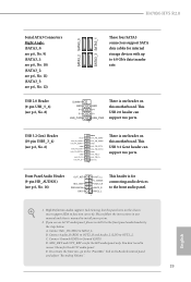
... this motherboard. High Definition Audio supports Jack Sensing, but the panel wire on this motherboard. D. If you use an AC'97 audio panel, please install it to 6.0 Gb/s data transfer rate. H470M-HVS R2.0 Serial ATA3 Connectors Right Angle: (SATA3_0: see p.6, No. 9) (SATA3_1: see p.6, No. 10) (SATA3_2: see p.6, No. 11) (SATA3_3: see p.6, No. 12) USB 2.0 Header (9-pin USB_5_6) (see p.6, No. 8) SATA3_2 SATA3_0 SATA3_3 SATA3_1 These four SATA3 connectors support SATA data cables for internal storage devices...
... this motherboard. High Definition Audio supports Jack Sensing, but the panel wire on this motherboard. D. If you use an AC'97 audio panel, please install it to 6.0 Gb/s data transfer rate. H470M-HVS R2.0 Serial ATA3 Connectors Right Angle: (SATA3_0: see p.6, No. 9) (SATA3_1: see p.6, No. 10) (SATA3_2: see p.6, No. 11) (SATA3_3: see p.6, No. 12) USB 2.0 Header (9-pin USB_5_6) (see p.6, No. 8) SATA3_2 SATA3_0 SATA3_3 SATA3_1 These four SATA3 connectors support SATA data cables for internal storage devices...

User Manual
Page 24
... motherboard provides a 4-Pin CPU fan (Quiet Fan) connector. English 20 To use a 4-pin ATX power supply, please plug it to Pin 1-3. If you plan to connect a 3-Pin CPU fan, please connect it along Pin 1 and Pin 13. Do not plug the PCIe power cable to this connector. CPU Fan Connector (4-pin CPU_FAN1) (see p.6, No. 2) a 3-Pin chassis water cooler fan, please connect it along Pin 1 and Pin 5. *Warning: Please make sure that the power cable connected is for the CPU and not the graphics card. Chassis/Water Pump Fan This motherboard provides one FAN_SPEED Connector...
... motherboard provides a 4-Pin CPU fan (Quiet Fan) connector. English 20 To use a 4-pin ATX power supply, please plug it to Pin 1-3. If you plan to connect a 3-Pin CPU fan, please connect it along Pin 1 and Pin 13. Do not plug the PCIe power cable to this connector. CPU Fan Connector (4-pin CPU_FAN1) (see p.6, No. 2) a 3-Pin chassis water cooler fan, please connect it along Pin 1 and Pin 5. *Warning: Please make sure that the power cable connected is for the CPU and not the graphics card. Chassis/Water Pump Fan This motherboard provides one FAN_SPEED Connector...

User Manual
Page 26
... Utilities Menu The Utilities Menu shows the application software that enhance the motherboard's features. Chapter 3 Software and Utilities Operation 3.1 Installing Drivers The Support CD that comes with the motherboard contains necessary drivers and useful utilities that the motherboard supports. Therefore, the drivers you install can work properly. Click on the support CD driver page. If the Main Menu does not appear automatically, locate and double click on the file "ASRSETUP.EXE" in your CD-ROM drive. Please click Install...
... Utilities Menu The Utilities Menu shows the application software that enhance the motherboard's features. Chapter 3 Software and Utilities Operation 3.1 Installing Drivers The Support CD that comes with the motherboard contains necessary drivers and useful utilities that the motherboard supports. Therefore, the drivers you install can work properly. Click on the support CD driver page. If the Main Menu does not appear automatically, locate and double click on the file "ASRSETUP.EXE" in your CD-ROM drive. Please click Install...

User Manual
Page 42
... This service controls thermal based voltage optimizations for DDR4 modules. DRAM Configuration Memory Information Allows users to allow for better power saving and heat dissipation. DRAM Timing Configuration Load XMP Setting Load XMP settings to switch between multiple frequencies and voltage points for hardware controlled P-states. DRAM Frequency If [Auto] is selected, the motherboard will set before OS handoff. Intel SpeedStep Technology Intel SpeedStep technology allows processors to overclock the memory and perform beyond standard specifications. Boot Performance Mode Select...
... This service controls thermal based voltage optimizations for DDR4 modules. DRAM Configuration Memory Information Allows users to allow for better power saving and heat dissipation. DRAM Timing Configuration Load XMP Setting Load XMP settings to switch between multiple frequencies and voltage points for hardware controlled P-states. DRAM Frequency If [Auto] is selected, the motherboard will set before OS handoff. Intel SpeedStep Technology Intel SpeedStep technology allows processors to overclock the memory and perform beyond standard specifications. Boot Performance Mode Select...
User Manual
Page 47
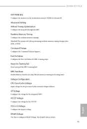
... Configure the Command Tristate Support. GT Voltage Configure the voltage for MRC training steps. Reset On Training Fail Reset system if the MRC training fails. Advanced Setting ASRock Timing Optimization Configure the fast path through the MRC. H470M-HVS R2.0 ODT PARK (B1) Configure the memory on die termination resistors' PARK for booting faster. Realtime Memory Timing Configure the realtime memory timings. [Enabled] The system will allow performing realtime memory timing changes...
... Configure the Command Tristate Support. GT Voltage Configure the voltage for MRC training steps. Reset On Training Fail Reset system if the MRC training fails. Advanced Setting ASRock Timing Optimization Configure the fast path through the MRC. H470M-HVS R2.0 ODT PARK (B1) Configure the memory on die termination resistors' PARK for booting faster. Realtime Memory Timing Configure the realtime memory timings. [Enabled] The system will allow performing realtime memory timing changes...

User Manual
Page 52
VT-d Intel® Virtualization Technology for PCIE1. 48 English SR-IOV Support If system has SR-IOV capable PCIe Devices, this option Enables or Disables Single Root IO Virtualization Support. DMI Link Speed Configure DMI Slot Link Speed. PCIE1 Link Speed Select the link speed for Directed I/O helps your virtual machine monitor better utilize hardware by improving application compatibility and reliability, and providing additional levels of manageability, security, isolation, and I/O performance...
VT-d Intel® Virtualization Technology for PCIE1. 48 English SR-IOV Support If system has SR-IOV capable PCIe Devices, this option Enables or Disables Single Root IO Virtualization Support. DMI Link Speed Configure DMI Slot Link Speed. PCIE1 Link Speed Select the link speed for Directed I/O helps your virtual machine monitor better utilize hardware by improving application compatibility and reliability, and providing additional levels of manageability, security, isolation, and I/O performance...

User Manual
Page 53
... graphics processor when the system boots up. H470M-HVS R2.0 PCIE2 Link Speed Select the link speed for the onboard digital outputs. 49 English Onboard LAN Enable or disable the onboard network interface controller. IGPU Multi-Monitor Select disable to keep the integrated graphics enabled at all PCH PCIE devices. Front Panel Enable/disable front panel HD audio. PCI Express Native Control Select Enable for all times. PCH PCIE ASPM Support This option enables/disables the ASPM support for enhanced PCI Express power saving in OS. Select enable to disable the integrated graphics...
... graphics processor when the system boots up. H470M-HVS R2.0 PCIE2 Link Speed Select the link speed for the onboard digital outputs. 49 English Onboard LAN Enable or disable the onboard network interface controller. IGPU Multi-Monitor Select disable to keep the integrated graphics enabled at all PCH PCIE devices. Front Panel Enable/disable front panel HD audio. PCI Express Native Control Select Enable for all times. PCH PCIE ASPM Support This option enables/disables the ASPM support for enhanced PCI Express power saving in OS. Select enable to disable the integrated graphics...
User Manual
Page 60
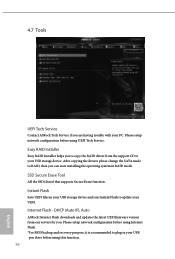
... can start installing the operating system in your USB storage device and run Instant Flash to plug in your UEFI. Instant Flash Save UEFI files in RAID mode. Internet Flash - Please setup network configuration before using Internet Flash. *For BIOS backup and recovery purpose, it is recommended to update your USB pen drive before using this function. 56 English 4.7 Tools UEFI Tech Service Contact ASRock Tech Service if you are having trouble with your USB storage device. After copying the drivers please change the SATA mode to...
... can start installing the operating system in your USB storage device and run Instant Flash to plug in your UEFI. Instant Flash Save UEFI files in RAID mode. Internet Flash - Please setup network configuration before using Internet Flash. *For BIOS backup and recovery purpose, it is recommended to update your USB pen drive before using this function. 56 English 4.7 Tools UEFI Tech Service Contact ASRock Tech Service if you are having trouble with your USB storage device. After copying the drivers please change the SATA mode to...

User Manual
Page 61
H470M-HVS R2.0 Internet Setting Enable or disable sound effects in the setup utility. UEFI Download Server Select a server to configure internet connection settings for Internet Flash. Network Configuration Use this to download the UEFI firmware. English 57
H470M-HVS R2.0 Internet Setting Enable or disable sound effects in the setup utility. UEFI Download Server Select a server to configure internet connection settings for Internet Flash. Network Configuration Use this to download the UEFI firmware. English 57

User Manual
Page 64
... enter to enable or disable support for the administrator account. Intel(R) Platform Trust Technology Enable/disable Intel PTT in the UEFI Setup Utility. 4.9 Security Screen In this section you may also clear the user password. Supervisor Password Set or change the settings in the UEFI Setup Utility. Secure Boot Use this option to change the password for Secure Boot. Leave it blank and press enter to change the password for the system. Users are unable to remove the password. Disable this item to remove the password...
... enter to enable or disable support for the administrator account. Intel(R) Platform Trust Technology Enable/disable Intel PTT in the UEFI Setup Utility. 4.9 Security Screen In this section you may also clear the user password. Supervisor Password Set or change the settings in the UEFI Setup Utility. Secure Boot Use this option to change the password for Secure Boot. Leave it blank and press enter to change the password for the system. Users are unable to remove the password. Disable this item to remove the password...

RAID Installation Guide
Page 7
...save the configuration changes and exit setup. STEP 4: Install Windows® 10 64-bit OS on your USB flash drive into a USB port B. Enter UEFI SETUP UTILITY Tool and highlight "Easy RAID Installer". Press to [RAID]. STEP 3: Set RAID configuration Please refer to p.8 -17 of this feature is not available for instructions on how to enter BIOS setup utility. STEP 1: Setting the BIOS RAID Items After installing the hard disk drives, please set RAID configuration. STEP 2: Use ASRock Easy RAID Installer Easy RAID Installer can copy the RAID driver from a support CD to...
...save the configuration changes and exit setup. STEP 4: Install Windows® 10 64-bit OS on your USB flash drive into a USB port B. Enter UEFI SETUP UTILITY Tool and highlight "Easy RAID Installer". Press to [RAID]. STEP 3: Set RAID configuration Please refer to p.8 -17 of this feature is not available for instructions on how to enter BIOS setup utility. STEP 1: Setting the BIOS RAID Items After installing the hard disk drives, please set RAID configuration. STEP 2: Use ASRock Easy RAID Installer Easy RAID Installer can copy the RAID driver from a support CD to...

RAID Installation Guide
Page 23
... download the drivers from ASRock's website and unzip the files into a USB flash disk or copy the files from ASRock's motherboard support CD. (Please copy the files under the following directory: 32 bit: ..\i386\Win7_Intel.. 64-bit: ..\AMD64\Win7-64_Intel.. STEP 2: Install Windows® 10 64-bit OS Press to launch boot menu at system POST and choose the item "UEFI:" to use Windows® 10 64-bit. Installing Windows® on a HDD larger than 2TB in RAID mode Windows...
... download the drivers from ASRock's website and unzip the files into a USB flash disk or copy the files from ASRock's motherboard support CD. (Please copy the files under the following directory: 32 bit: ..\i386\Win7_Intel.. 64-bit: ..\AMD64\Win7-64_Intel.. STEP 2: Install Windows® 10 64-bit OS Press to launch boot menu at system POST and choose the item "UEFI:" to use Windows® 10 64-bit. Installing Windows® on a HDD larger than 2TB in RAID mode Windows...

RAID Installation Guide
Page 25
If you encounter this problem, you install Windows® 10 64-bit on a large hard disk (ex. Windows® 10 64-bit: A. After installing Windows® 10 64-bit, install the hotfix kb2505454. (This may take about 5 minutes to boot into Windows® or install driver/utilities. Windows® will need to follow the instructions below to install motherboard drivers and utilities. 25 Please start to fix this problem. If you will install this hotfix then reboot...
If you encounter this problem, you install Windows® 10 64-bit on a large hard disk (ex. Windows® 10 64-bit: A. After installing Windows® 10 64-bit, install the hotfix kb2505454. (This may take about 5 minutes to boot into Windows® or install driver/utilities. Windows® will need to follow the instructions below to install motherboard drivers and utilities. 25 Please start to fix this problem. If you will install this hotfix then reboot...

Intel Rapid Storage Guide
Page 13
... Manufacturer-supplied hardware support disk into Drive A:, insert ;a floppy disk containing the following steps to create a floppy disk with a screen asking you have successfully installed the driver and Windows setup should continue. Press Enter. 5. At this point, you to scroll through the list as all controllers may not be prompted Note with the Note necessary files. 4. 7. Use the Floppy Configuration Utility to install the Intel Rapid Storage Technology driver during text-mode phase). Install the RAID Driver Using the F6 Installation...
... Manufacturer-supplied hardware support disk into Drive A:, insert ;a floppy disk containing the following steps to create a floppy disk with a screen asking you have successfully installed the driver and Windows setup should continue. Press Enter. 5. At this point, you to scroll through the list as all controllers may not be prompted Note with the Note necessary files. 4. 7. Use the Floppy Configuration Utility to install the Intel Rapid Storage Technology driver during text-mode phase). Install the RAID Driver Using the F6 Installation...


